bolt BMW 3 SERIES 1985 E30 Workshop Manual
[x] Cancel search | Manufacturer: BMW, Model Year: 1985, Model line: 3 SERIES, Model: BMW 3 SERIES 1985 E30Pages: 228, PDF Size: 7.04 MB
Page 166 of 228
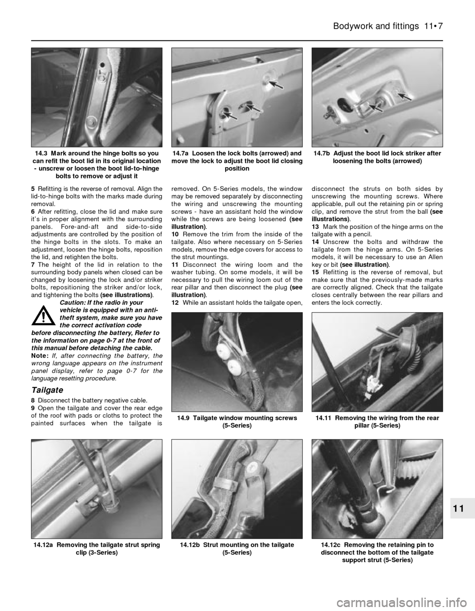
5Refitting is the reverse of removal. Align the
lid-to-hinge bolts with the marks made during
removal.
6After refitting, close the lid and make sure
it’s in proper alignment with the surrounding
panels. Fore-and-aft and side-to-side
adjustments are controlled by the position of
the hinge bolts in the slots. To make an
adjustment, loosen the hinge bolts, reposition
the lid, and retighten the bolts.
7The height of the lid in relation to the
surrounding body panels when closed can be
changed by loosening the lock and/or striker
bolts, repositioning the striker and/or lock,
and tightening the bolts (see illustrations).
Caution: If the radio in your
vehicle is equipped with an anti-
theft system, make sure you have
the correct activation code
before disconnecting the battery, Refer to
the information on page 0-7 at the front of
this manual before detaching the cable.
Note: If, after connecting the battery, the
wrong language appears on the instrument
panel display, refer to page 0-7 for the
language resetting procedure.
Tailgate
8Disconnect the battery negative cable.
9Open the tailgate and cover the rear edge
of the roof with pads or cloths to protect the
painted surfaces when the tailgate isremoved. On 5-Series models, the window
may be removed separately by disconnecting
the wiring and unscrewing the mounting
screws - have an assistant hold the window
while the screws are being loosened (see
illustration).
10Remove the trim from the inside of the
tailgate. Also where necessary on 5-Series
models, remove the edge covers for access to
the strut mountings.
11Disconnect the wiring loom and the
washer tubing. On some models, it will be
necessary to pull the wiring loom out of the
rear pillar and then disconnect the plug (see
illustration).
12While an assistant holds the tailgate open,disconnect the struts on both sides by
unscrewing the mounting screws. Where
applicable, pull out the retaining pin or spring
clip, and remove the strut from the ball (see
illustrations).
13Mark the position of the hinge arms on the
tailgate with a pencil.
14Unscrew the bolts and withdraw the
tailgate from the hinge arms. On 5-Series
models, it will be necessary to use an Allen
key or bit (see illustration).
15Refitting is the reverse of removal, but
make sure that the previously-made marks
are correctly aligned. Check that the tailgate
closes centrally between the rear pillars and
enters the lock correctly.
Bodywork and fittings 11•7
14.7b Adjust the boot lid lock striker after
loosening the bolts (arrowed)14.7a Loosen the lock bolts (arrowed) and
move the lock to adjust the boot lid closing
position14.3 Mark around the hinge bolts so you
can refit the boot lid in its original location
- unscrew or loosen the boot lid-to-hinge
bolts to remove or adjust it
14.12c Removing the retaining pin to
disconnect the bottom of the tailgate
support strut (5-Series)14.12b Strut mounting on the tailgate
(5-Series)14.12a Removing the tailgate strut spring
clip (3-Series)
14.11 Removing the wiring from the rear
pillar (5-Series)14.9 Tailgate window mounting screws
(5-Series)
11
Page 167 of 228
15 Latch, lock cylinder and
handles- removal, refitting
and adjustment
1
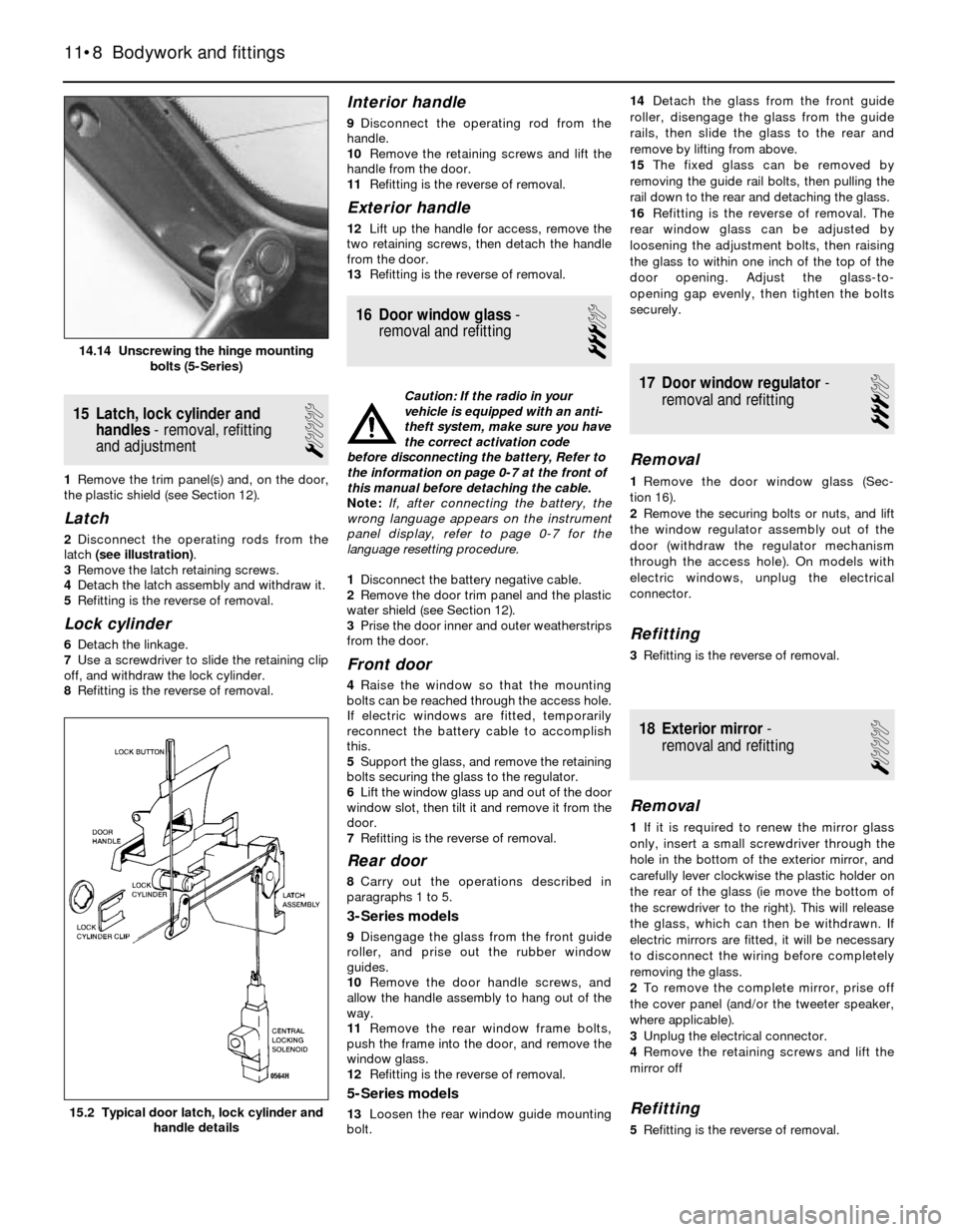
1Remove the trim panel(s) and, on the door,
the plastic shield (see Section 12).
Latch
2Disconnect the operating rods from the
latch (see illustration).
3Remove the latch retaining screws.
4Detach the latch assembly and withdraw it.
5Refitting is the reverse of removal.
Lock cylinder
6Detach the linkage.
7Use a screwdriver to slide the retaining clip
off, and withdraw the lock cylinder.
8Refitting is the reverse of removal.
Interior handle
9Disconnect the operating rod from the
handle.
10Remove the retaining screws and lift the
handle from the door.
11Refitting is the reverse of removal.
Exterior handle
12Lift up the handle for access, remove the
two retaining screws, then detach the handle
from the door.
13Refitting is the reverse of removal.
16 Door window glass-
removal and refitting
3
Caution: If the radio in your
vehicle is equipped with an anti-
theft system, make sure you have
the correct activation code
before disconnecting the battery, Refer to
the information on page 0-7 at the front of
this manual before detaching the cable.
Note: If, after connecting the battery, the
wrong language appears on the instrument
panel display, refer to page 0-7 for the
language resetting procedure.
1Disconnect the battery negative cable.
2Remove the door trim panel and the plastic
water shield (see Section 12).
3Prise the door inner and outer weatherstrips
from the door.
Front door
4Raise the window so that the mounting
bolts can be reached through the access hole.
If electric windows are fitted, temporarily
reconnect the battery cable to accomplish
this.
5Support the glass, and remove the retaining
bolts securing the glass to the regulator.
6Lift the window glass up and out of the door
window slot, then tilt it and remove it from the
door.
7Refitting is the reverse of removal.
Rear door
8Carry out the operations described in
paragraphs 1 to 5.
3-Series models
9Disengage the glass from the front guide
roller, and prise out the rubber window
guides.
10Remove the door handle screws, and
allow the handle assembly to hang out of the
way.
11Remove the rear window frame bolts,
push the frame into the door, and remove the
window glass.
12Refitting is the reverse of removal.
5-Series models
13Loosen the rear window guide mounting
bolt.14Detach the glass from the front guide
roller, disengage the glass from the guide
rails, then slide the glass to the rear and
remove by lifting from above.
15The fixed glass can be removed by
removing the guide rail bolts, then pulling the
rail down to the rear and detaching the glass.
16Refitting is the reverse of removal. The
rear window glass can be adjusted by
loosening the adjustment bolts, then raising
the glass to within one inch of the top of the
door opening. Adjust the glass-to-
opening gap evenly, then tighten the bolts
securely.
17 Door window regulator-
removal and refitting
3
Removal
1Remove the door window glass (Sec-
tion 16).
2Remove the securing bolts or nuts, and lift
the window regulator assembly out of the
door (withdraw the regulator mechanism
through the access hole). On models with
electric windows, unplug the electrical
connector.
Refitting
3Refitting is the reverse of removal.
18 Exterior mirror-
removal and refitting
1
Removal
1If it is required to renew the mirror glass
only, insert a small screwdriver through the
hole in the bottom of the exterior mirror, and
carefully lever clockwise the plastic holder on
the rear of the glass (ie move the bottom of
the screwdriver to the right). This will release
the glass, which can then be withdrawn. If
electric mirrors are fitted, it will be necessary
to disconnect the wiring before completely
removing the glass.
2To remove the complete mirror, prise off
the cover panel (and/or the tweeter speaker,
where applicable).
3Unplug the electrical connector.
4Remove the retaining screws and lift the
mirror off
Refitting
5Refitting is the reverse of removal.
11•8 Bodywork and fittings
15.2 Typical door latch, lock cylinder and
handle details
14.14 Unscrewing the hinge mounting
bolts (5-Series)
Page 168 of 228
19 Steering column shrouds -
removal and refitting
1
Caution: If the radio in your
vehicle is equipped with an anti-
theft system, make sure you have
the correct activation code
before disconnecting the battery, Refer to
the information on page 0-7 at the front of
this manual before detaching the cable.
Note: If, after connecting the battery, the
wrong language appears on the instrument
panel display, refer to page 0-7 for the
language resetting procedure.
Removal
1Disconnect the battery negative cable.
2Remove the steering wheel (Chapter 10).
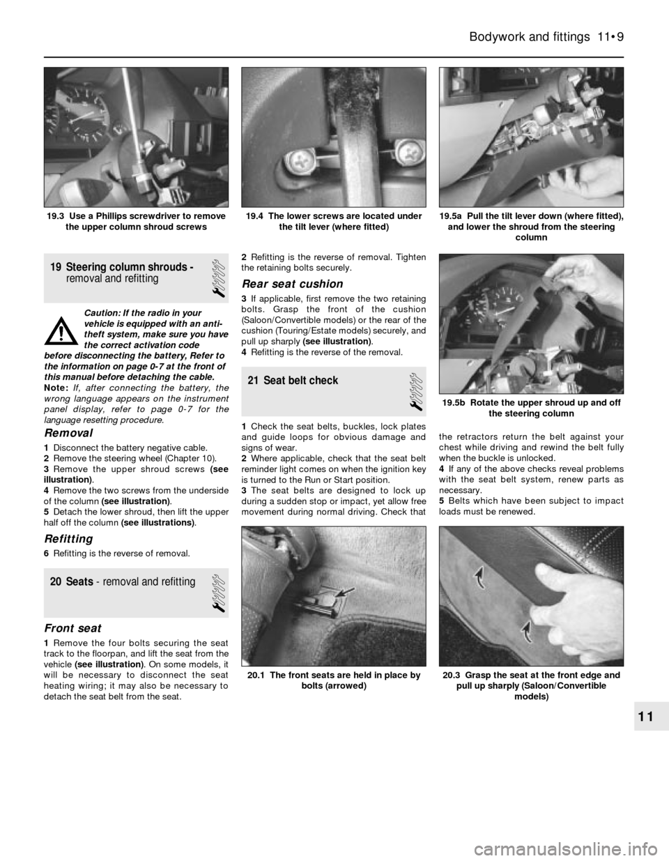
3Remove the upper shroud screws (see
illustration).
4Remove the two screws from the underside
of the column (see illustration).
5Detach the lower shroud, then lift the upper
half off the column (see illustrations).
Refitting
6Refitting is the reverse of removal.
20 Seats- removal and refitting
1
Front seat
1Remove the four bolts securing the seat
track to the floorpan, and lift the seat from the
vehicle (see illustration). On some models, it
will be necessary to disconnect the seat
heating wiring; it may also be necessary to
detach the seat belt from the seat.2Refitting is the reverse of removal. Tighten
the retaining bolts securely.
Rear seat cushion
3If applicable, first remove the two retaining
bolts. Grasp the front of the cushion
(Saloon/Convertible models) or the rear of the
cushion (Touring/Estate models) securely, and
pull up sharply (see illustration).
4Refitting is the reverse of the removal.
21 Seat belt check
1
1Check the seat belts, buckles, lock plates
and guide loops for obvious damage and
signs of wear.
2Where applicable, check that the seat belt
reminder light comes on when the ignition key
is turned to the Run or Start position.
3The seat belts are designed to lock up
during a sudden stop or impact, yet allow free
movement during normal driving. Check thatthe retractors return the belt against your
chest while driving and rewind the belt fully
when the buckle is unlocked.
4If any of the above checks reveal problems
with the seat belt system, renew parts as
necessary.
5Belts which have been subject to impact
loads must be renewed.
Bodywork and fittings 11•9
19.5a Pull the tilt lever down (where fitted),
and lower the shroud from the steering
column19.4 The lower screws are located under
the tilt lever (where fitted)19.3 Use a Phillips screwdriver to remove
the upper column shroud screws
20.3 Grasp the seat at the front edge and
pull up sharply (Saloon/Convertible
models)20.1 The front seats are held in place by
bolts (arrowed)
19.5b Rotate the upper shroud up and off
the steering column
11
Page 170 of 228
Finding a short-circuit
One method of finding a short-circuit is to
remove the fuse and connect a test light or
voltmeter in its place. There should be no
voltage present in the circuit. Move the
electrical connectors from side-to-side while
watching the test light. If the bulb goes on,
there is a short to earth somewhere in that
area, probably where the insulation has been
rubbed through. The same test can be
performed on each component in a circuit,
even a switch.
Earth check
Perform a earth check to see whether a
component is properly earthed (passing
current back via the vehicle body). Disconnect
the battery, and connect one lead of a self-
powered test light (often known as a
continuity tester) to a known good earth.
Connect the other lead to the wire or earth
connection being tested. The bulb should
light, indicating a good earth connection. If
not, dismantle the connection, and clean all
relevant parts thoroughly. When re-making
the connection, use serrated (shakeproof)
washers if possible, and tighten all bolts, etc,
securely.
Caution: If the radio in your
vehicle is equipped with an anti-
theft system, make sure you have
the correct activation code
before disconnecting the battery, Refer to
the information on page 0-7 at the front of
this manual before detaching the cable.
Note: If, after connecting the battery, the
wrong language appears on the instrument
panel display, refer to page 0-7 for the
language resetting procedure.
Continuity check
A continuity check determines if there are
any breaks in a circuit - if it is conducting
electricity properly. With the circuit off (no
power in the circuit), a self-powered continuity
tester can be used to check the circuit.
Connect the test leads to both ends of the
circuit, and if the test light comes on, the
circuit is passing current properly. If the light
doesn’t come on, there is a break somewhere
in the circuit. The same procedure can be
used to test a switch, by connecting the
continuity tester to the power-in and power-
out sides of the switch. With the switch turned
on, the test light should come on.
Finding an open-circuit
When diagnosing for possible open-
circuits, it is often difficult to locate them by
sight, because oxidation or terminal
misalignment are hidden by the connectors.
Intermittent problems are often caused by
oxidised or loose connections. Merely
wiggling an electrical connector may correct
the open-circuit condition, albeit temporarily.
Dismantle the connector, and spray with a
water-dispersant aerosol. On simpler
connectors, it may be possible to carefullybend the connector pins inside, to improve
the metal-to-metal contact - don’t damage
the connector in the process, however.
3 Fuses- general information
1
The electrical circuits of the vehicle are
protected by a combination of fuses and
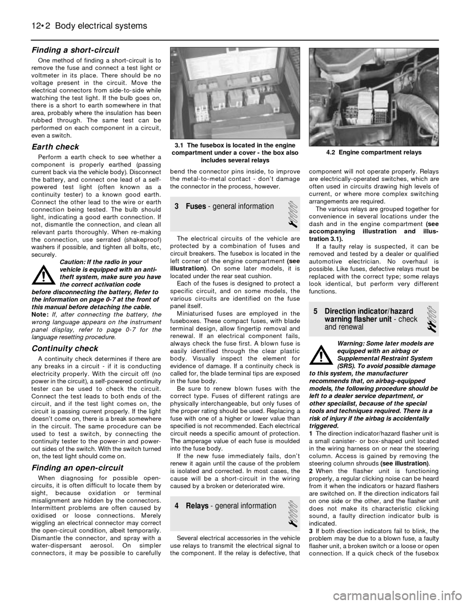
circuit breakers. The fusebox is located in the
left corner of the engine compartment (see
illustration). On some later models, it is
located under the rear seat cushion.
Each of the fuses is designed to protect a
specific circuit, and on some models, the
various circuits are identified on the fuse
panel itself.
Miniaturised fuses are employed in the
fuseboxes. These compact fuses, with blade
terminal design, allow fingertip removal and
renewal. If an electrical component fails,
always check the fuse first. A blown fuse is
easily identified through the clear plastic
body. Visually inspect the element for
evidence of damage. If a continuity check is
called for, the blade terminal tips are exposed
in the fuse body.
Be sure to renew blown fuses with the
correct type. Fuses of different ratings are
physically interchangeable, but only fuses of
the proper rating should be used. Replacing a
fuse with one of a higher or lower value than
specified is not recommended. Each electrical
circuit needs a specific amount of protection.
The amperage value of each fuse is moulded
into the fuse body.
If the new fuse immediately fails, don’t
renew it again until the cause of the problem
is isolated and corrected. In most cases, the
cause will be a short-circuit in the wiring
caused by a broken or deteriorated wire.
4 Relays- general information
1
Several electrical accessories in the vehicle
use relays to transmit the electrical signal to
the component. If the relay is defective, thatcomponent will not operate properly. Relays
are electrically-operated switches, which are
often used in circuits drawing high levels of
current, or where more complex switching
arrangements are required.
The various relays are grouped together for
convenience in several locations under the
dash and in the engine compartment (see
accompanying illustration and illus-
tration 3.1).
If a faulty relay is suspected, it can be
removed and tested by a dealer or qualified
automotive electrician. No overhaul is
possible. Like fuses, defective relays must be
replaced with the correct type; some relays
look identical, but perform very different
functions.
5 Direction indicator/hazard
warning flasher unit- check
and renewal
2
Warning: Some later models are
equipped with an airbag or
Supplemental Restraint System
(SRS). To avoid possible damage
to this system, the manufacturer
recommends that, on airbag-equipped
models, the following procedure should be
left to a dealer service department, or
other specialist, because of the special
tools and techniques required. There is a
risk of injury if the airbag is accidentally
triggered.
1The direction indicator/hazard flasher unit is
a small canister- or box-shaped unit located
in the wiring harness on or near the steering
column. Access is gained by removing the
steering column shrouds (see illustration).
2When the flasher unit is functioning
properly, a regular clicking noise can be heard
from it when the indicators or hazard flashers
are switched on. If the direction indicators fail
on one side or the other, and the flasher unit
does not make its characteristic clicking
sound, a faulty direction indicator bulb is
indicated.
3If both direction indicators fail to blink, the
problem may be due to a blown fuse, a faulty
flasher unit, a broken switch or a loose or open
connection. If a quick check of the fusebox
12•2 Body electrical systems
4.2 Engine compartment relays3.1 The fusebox is located in the engine
compartment under a cover - the box also
includes several relays
Page 172 of 228
8 Radio- removal and refitting
1
Caution: If the radio in your
vehicle is equipped with an anti-
theft system, make sure you have
the correct activation code
before disconnecting the battery, Refer to
the information on page 0-7 at the front of
this manual before detaching the cable.
Note: If, after connecting the battery, the
wrong language appears on the instrument
panel display, refer to page 0-7 for the
language resetting procedure.
Removal
1Disconnect the battery negative cable.
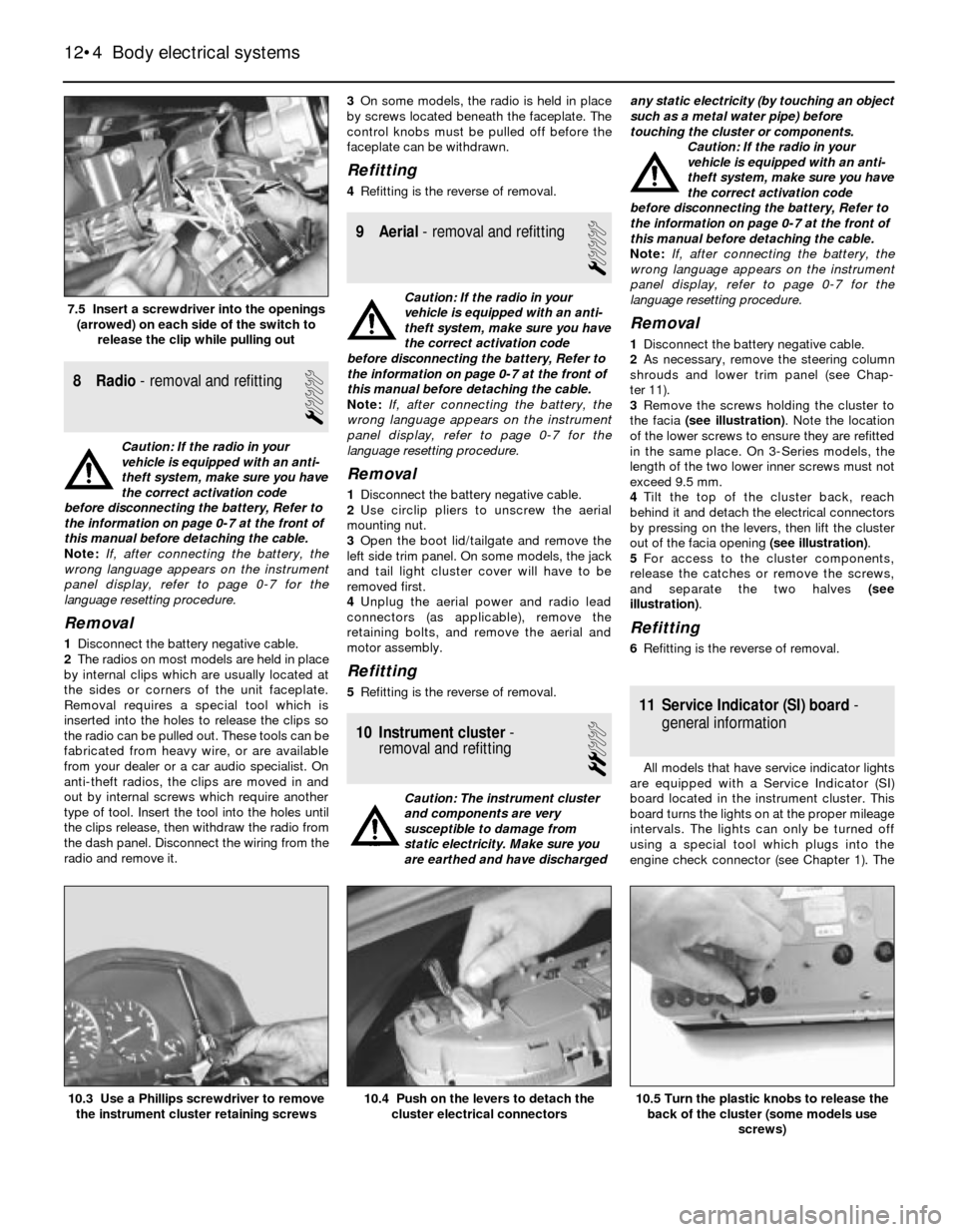
2The radios on most models are held in place
by internal clips which are usually located at
the sides or corners of the unit faceplate.
Removal requires a special tool which is
inserted into the holes to release the clips so
the radio can be pulled out. These tools can be
fabricated from heavy wire, or are available
from your dealer or a car audio specialist. On
anti-theft radios, the clips are moved in and
out by internal screws which require another
type of tool. Insert the tool into the holes until
the clips release, then withdraw the radio from
the dash panel. Disconnect the wiring from the
radio and remove it.3On some models, the radio is held in place
by screws located beneath the faceplate. The
control knobs must be pulled off before the
faceplate can be withdrawn.
Refitting
4Refitting is the reverse of removal.
9 Aerial- removal and refitting
1
Caution: If the radio in your
vehicle is equipped with an anti-
theft system, make sure you have
the correct activation code
before disconnecting the battery, Refer to
the information on page 0-7 at the front of
this manual before detaching the cable.
Note: If, after connecting the battery, the
wrong language appears on the instrument
panel display, refer to page 0-7 for the
language resetting procedure.
Removal
1Disconnect the battery negative cable.
2Use circlip pliers to unscrew the aerial
mounting nut.
3Open the boot lid/tailgate and remove the
left side trim panel. On some models, the jack
and tail light cluster cover will have to be
removed first.
4Unplug the aerial power and radio lead
connectors (as applicable), remove the
retaining bolts, and remove the aerial and
motor assembly.
Refitting
5Refitting is the reverse of removal.
10 Instrument cluster-
removal and refitting
2
Caution: The instrument cluster
and components are very
susceptible to damage from
static electricity. Make sure you
are earthed and have dischargedany static electricity (by touching an object
such as a metal water pipe) before
touching the cluster or components.
Caution: If the radio in your
vehicle is equipped with an anti-
theft system, make sure you have
the correct activation code
before disconnecting the battery, Refer to
the information on page 0-7 at the front of
this manual before detaching the cable.
Note: If, after connecting the battery, the
wrong language appears on the instrument
panel display, refer to page 0-7 for the
language resetting procedure.
Removal
1Disconnect the battery negative cable.
2As necessary, remove the steering column
shrouds and lower trim panel (see Chap-
ter 11).
3Remove the screws holding the cluster to
the facia (see illustration). Note the location
of the lower screws to ensure they are refitted
in the same place. On 3-Series models, the
length of the two lower inner screws must not
exceed 9.5 mm.
4Tilt the top of the cluster back, reach
behind it and detach the electrical connectors
by pressing on the levers, then lift the cluster
out of the facia opening (see illustration).
5For access to the cluster components,
release the catches or remove the screws,
and separate the two halves (see
illustration).
Refitting
6Refitting is the reverse of removal.
11 Service Indicator (SI) board-
general information
All models that have service indicator lights
are equipped with a Service Indicator (SI)
board located in the instrument cluster. This
board turns the lights on at the proper mileage
intervals. The lights can only be turned off
using a special tool which plugs into the
engine check connector (see Chapter 1). The
12•4 Body electrical systems
10.5 Turn the plastic knobs to release the
back of the cluster (some models use
screws)10.4 Push on the levers to detach the
cluster electrical connectors10.3 Use a Phillips screwdriver to remove
the instrument cluster retaining screws
7.5 Insert a screwdriver into the openings
(arrowed) on each side of the switch to
release the clip while pulling out
Page 175 of 228
16 Windscreen/tailgate wiper
motor- removal and refitting
2
Caution: If the radio in your
vehicle is equipped with an anti-
theft system, make sure you have
the correct activation code
before disconnecting the battery, Refer to
the information on page 0-7 at the front of
this manual before detaching the cable.
Note: If, after connecting the battery, the
wrong language appears on the instrument
panel display, refer to page 0-7 for the
language resetting procedure.
1Disconnect the battery negative cable.
Windscreen wiper motor
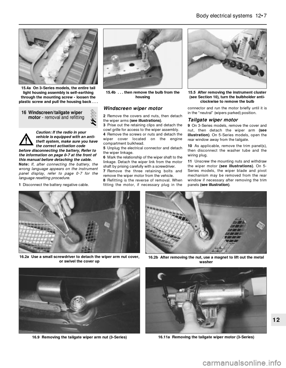
2Remove the covers and nuts, then detach
the wiper arms (see illustrations).
3Prise out the retaining clips and detach the
cowl grille for access to the wiper assembly.
4Remove the screws or nuts and detach the
wiper cover located on the engine
compartment bulkhead.
5Unplug the electrical connector and detach
the wiper linkage.
6Mark the relationship of the wiper shaft to the
linkage. Detach the wiper link from the motor
shaft by prising carefully with a screwdriver.
7Remove the three retaining bolts and
remove the wiper motor from the vehicle.
8Refitting is the reverse of removal. When
fitting the motor, if necessary plug in theconnector and run the motor briefly until it is
in the “neutral” (wipers parked) position.Tailgate wiper motor
9On 3-Series models, remove the cover and
nut, then detach the wiper arm (see
illustration). On 5-Series models, open the
rear window away from the tailgate.
10As applicable, remove the trim panel(s),
then disconnect the washer tube and the
wiring plug.
11Unscrew the mounting nuts and withdraw
the wiper motor (see illustrations). On 5-
Series models, the wiper blade and pivot
mechanism may be removed from the rear
window if necessary after removing the trim
panels (see illustration).
Body electrical systems 12•7
15.5 After removing the instrument cluster
(see Section 10), turn the bulbholder anti-
clockwise to remove the bulb15.4b . . . then remove the bulb from the
housing15.4a On 3-Series models, the entire tail
light housing assembly is self-earthing
through the mounting screw - loosen the
plastic screw and pull the housing back . . .
16.11a Removing the tailgate wiper motor (3-Series)
16.2b After removing the nut, use a magnet to lift out the metal
washer16.2a Use a small screwdriver to detach the wiper arm nut cover,
or swivel the cover up
16.9 Removing the tailgate wiper arm nut (3-Series)
12
Page 204 of 228
REF•3
REF
MOT Test Checks
Exhaust system
MStart the engine. With your assistant
holding a rag over the tailpipe, check the
entire system for leaks. Repair or renew
leaking sections.
Jack up the front and rear of the vehicle,
and securely support it on axle stands.
Position the stands clear of the suspension
assemblies. Ensure that the wheels are
clear of the ground and that the steering
can be turned from lock to lock.
Steering mechanism
MHave your assistant turn the steering from
lock to lock. Check that the steering turns
smoothly, and that no part of the steering
mechanism, including a wheel or tyre, fouls
any brake hose or pipe or any part of the body
structure.
MExamine the steering rack rubber gaiters
for damage or insecurity of the retaining clips.
If power steering is fitted, check for signs of
damage or leakage of the fluid hoses, pipes or
connections. Also check for excessive
stiffness or binding of the steering, a missing
split pin or locking device, or severe corrosion
of the body structure within 30 cm of any
steering component attachment point.
Front and rear suspension and
wheel bearings
MStarting at the front right-hand side, grasp
the roadwheel at the 3 o’clock and 9 o’clock
positions and shake it vigorously. Check for
free play or insecurity at the wheel bearings,
suspension balljoints, or suspension mount-
ings, pivots and attachments.
MNow grasp the wheel at the 12 o’clock and
6 o’clock positions and repeat the previous
inspection. Spin the wheel, and check for
roughness or tightness of the front wheel
bearing.
MIf excess free play is suspected at a
component pivot point, this can be confirmed
by using a large screwdriver or similar tool and
levering between the mounting and the
component attachment. This will confirm
whether the wear is in the pivot bush, its
retaining bolt, or in the mounting itself (the bolt
holes can often become elongated).
MCarry out all the above checks at the other
front wheel, and then at both rear wheels.
Springs and shock absorbers
MExamine the suspension struts (when
applicable) for serious fluid leakage, corrosion,
or damage to the casing. Also check the
security of the mounting points.
MIf coil springs are fitted, check that the
spring ends locate in their seats, and that the
spring is not corroded, cracked or broken.
MIf leaf springs are fitted, check that all
leaves are intact, that the axle is securely
attached to each spring, and that there is no
deterioration of the spring eye mountings,
bushes, and shackles.MThe same general checks apply to vehicles
fitted with other suspension types, such as
torsion bars, hydraulic displacer units, etc.
Ensure that all mountings and attachments are
secure, that there are no signs of excessive
wear, corrosion or damage, and (on hydraulic
types) that there are no fluid leaks or damaged
pipes.
MInspect the shock absorbers for signs of
serious fluid leakage. Check for wear of the
mounting bushes or attachments, or damage
to the body of the unit.
Driveshafts
(fwd vehicles only)
MRotate each front wheel in turn and inspect
the constant velocity joint gaiters for splits or
damage. Also check that each driveshaft is
straight and undamaged.
Braking system
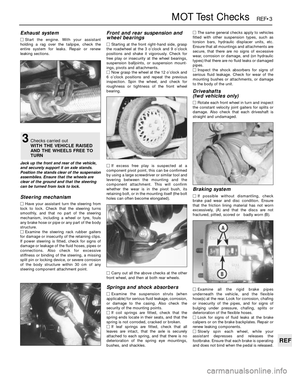
MIf possible without dismantling, check
brake pad wear and disc condition. Ensure
that the friction lining material has not worn
excessively, (A) and that the discs are not
fractured, pitted, scored or badly worn (B).
MExamine all the rigid brake pipes
underneath the vehicle, and the flexible
hose(s) at the rear. Look for corrosion, chafing
or insecurity of the pipes, and for signs of
bulging under pressure, chafing, splits or
deterioration of the flexible hoses.
MLook for signs of fluid leaks at the brake
calipers or on the brake backplates. Repair or
renew leaking components.
MSlowly spin each wheel, while your
assistant depresses and releases the
footbrake. Ensure that each brake is operating
and does not bind when the pedal is released.
3Checks carried out
WITH THE VEHICLE RAISED
AND THE WHEELS FREE TO
TURN
Page 209 of 228

REF•8General Repair Procedures
Whenever servicing, repair or overhaul work
is carried out on the car or its components,
observe the following procedures and
instructions. This will assist in carrying out the
operation efficiently and to a professional
standard of workmanship.
Joint mating faces and gaskets
When separating components at their
mating faces, never insert screwdrivers or
similar implements into the joint between the
faces in order to prise them apart. This can
cause severe damage which results in oil
leaks, coolant leaks, etc upon reassembly.
Separation is usually achieved by tapping
along the joint with a soft-faced hammer in
order to break the seal. However, note that
this method may not be suitable where
dowels are used for component location.
Where a gasket is used between the mating
faces of two components, a new one must be
fitted on reassembly; fit it dry unless otherwise
stated in the repair procedure. Make sure that
the mating faces are clean and dry, with all
traces of old gasket removed. When cleaning a
joint face, use a tool which is unlikely to score
or damage the face, and remove any burrs or
nicks with an oilstone or fine file.
Make sure that tapped holes are cleaned
with a pipe cleaner, and keep them free of
jointing compound, if this is being used,
unless specifically instructed otherwise.
Ensure that all orifices, channels or pipes
are clear, and blow through them, preferably
using compressed air.
Oil seals
Oil seals can be removed by levering them
out with a wide flat-bladed screwdriver or
similar implement. Alternatively, a number of
self-tapping screws may be screwed into the
seal, and these used as a purchase for pliers or
some similar device in order to pull the seal free.
Whenever an oil seal is removed from its
working location, either individually or as part
of an assembly, it should be renewed.
The very fine sealing lip of the seal is easily
damaged, and will not seal if the surface it
contacts is not completely clean and free from
scratches, nicks or grooves. If the original
sealing surface of the component cannot be
restored, and the manufacturer has not made
provision for slight relocation of the seal
relative to the sealing surface, the component
should be renewed.
Protect the lips of the seal from any surface
which may damage them in the course of
fitting. Use tape or a conical sleeve where
possible. Lubricate the seal lips with oil before
fitting and, on dual-lipped seals, fill the space
between the lips with grease.
Unless otherwise stated, oil seals must be
fitted with their sealing lips toward the
lubricant to be sealed.
Use a tubular drift or block of wood of the
appropriate size to install the seal and, if the
seal housing is shouldered, drive the seal
down to the shoulder. If the seal housing isunshouldered, the seal should be fitted with
its face flush with the housing top face (unless
otherwise instructed).
Screw threads and fastenings
Seized nuts, bolts and screws are quite a
common occurrence where corrosion has set
in, and the use of penetrating oil or releasing
fluid will often overcome this problem if the
offending item is soaked for a while before
attempting to release it. The use of an impact
driver may also provide a means of releasing
such stubborn fastening devices, when used
in conjunction with the appropriate
screwdriver bit or socket. If none of these
methods works, it may be necessary to resort
to the careful application of heat, or the use of
a hacksaw or nut splitter device.
Studs are usually removed by locking two
nuts together on the threaded part, and then
using a spanner on the lower nut to unscrew
the stud. Studs or bolts which have broken off
below the surface of the component in which
they are mounted can sometimes be removed
using a stud extractor. Always ensure that a
blind tapped hole is completely free from oil,
grease, water or other fluid before installing
the bolt or stud. Failure to do this could cause
the housing to crack due to the hydraulic
action of the bolt or stud as it is screwed in.
When tightening a castellated nut to accept
a split pin, tighten the nut to the specified
torque, where applicable, and then tighten
further to the next split pin hole. Never slacken
the nut to align the split pin hole, unless stated
in the repair procedure.
When checking or retightening a nut or bolt
to a specified torque setting, slacken the nut
or bolt by a quarter of a turn, and then
retighten to the specified setting. However,
this should not be attempted where angular
tightening has been used.
For some screw fastenings, notably
cylinder head bolts or nuts, torque wrench
settings are no longer specified for the latter
stages of tightening, “angle-tightening” being
called up instead. Typically, a fairly low torque
wrench setting will be applied to the
bolts/nuts in the correct sequence, followed
by one or more stages of tightening through
specified angles.
Locknuts, locktabs and washers
Any fastening which will rotate against a
component or housing during tightening
should always have a washer between it and
the relevant component or housing.
Spring or split washers should always be
renewed when they are used to lock a critical
component such as a big-end bearing
retaining bolt or nut. Locktabs which are
folded over to retain a nut or bolt should
always be renewed.
Self-locking nuts can be re-used in non-
critical areas, providing resistance can be felt
when the locking portion passes over the bolt
or stud thread. However, it should be noted
that self-locking stiffnuts tend to lose theireffectiveness after long periods of use, and
should then be renewed as a matter of course.
Split pins must always be replaced with
new ones of the correct size for the hole.
When thread-locking compound is found
on the threads of a fastener which is to be re-
used, it should be cleaned off with a wire
brush and solvent, and fresh compound
applied on reassembly.
Special tools
Some repair procedures in this manual
entail the use of special tools such as a press,
two or three-legged pullers, spring com-
pressors, etc. Wherever possible, suitable
readily-available alternatives to the manu-
facturer’s special tools are described, and are
shown in use. In some instances, where no
alternative is possible, it has been necessary
to resort to the use of a manufacturer’s tool,
and this has been done for reasons of safety
as well as the efficient completion of the repair
operation. Unless you are highly-skilled and
have a thorough understanding of the
procedures described, never attempt to
bypass the use of any special tool when the
procedure described specifies its use. Not
only is there a very great risk of personal
injury, but expensive damage could be
caused to the components involved.
Environmental considerations
When disposing of used engine oil, brake
fluid, antifreeze, etc, give due consideration to
any detrimental environmental effects. Do not,
for instance, pour any of the above liquids
down drains into the general sewage system,
or onto the ground to soak away. Many local
council refuse tips provide a facility for waste
oil disposal, as do some garages. If none of
these facilities are available, consult your local
Environmental Health Department, or the
National Rivers Authority, for further advice.
With the universal tightening-up of legis-
lation regarding the emission of environmen-
tally-harmful substances from motor vehicles,
most vehicles have tamperproof devices fitted
to the main adjustment points of the fuel
system. These devices are primarily designed
to prevent unqualified persons from adjusting
the fuel/air mixture, with the chance of a
consequent increase in toxic emissions. If
such devices are found during servicing or
overhaul, they should, wherever possible, be
renewed or refitted in accordance with the
manufacturer’s requirements or current
legislation.
Note: It is
antisocial and
illegal to dump
oil down the
drain. To find
the location of
your local oil
recycling
bank, call this
number free.
Page 211 of 228
REF•10Fault Finding
Engine will not rotate when attempting to start
m mBattery terminal connections loose or corroded (Chapter 1).
m mBattery discharged or faulty (Chapter 1).
m mAutomatic transmission not completely engaged in Park (Chap-
ter 7B) or (on models with a clutch switch) clutch not completely
depressed (Chapter 8).
m mBroken, loose or disconnected wiring in the starting circuit
(Chapters 5 and 12).
m mStarter motor pinion jammed in flywheel ring gear (Chapter 5).
m mStarter solenoid faulty (Chapter 5).
m mStarter motor faulty (Chapter 5).
m mIgnition switch faulty (Chapter 12).
m mStarter pinion or flywheel teeth worn or broken (Chapter 5).
m mEngine internal problem (Chapter 2B).
Engine rotates, but will not start
m
mFuel tank empty.
m mBattery discharged (engine rotates slowly) (Chapter 5).
m mBattery terminal connections loose or corroded (Chapter 1).
m mLeaking fuel injector(s), faulty fuel pump, pressure regulator, etc
(Chapter 4).
m mFuel not reaching fuel injection system or carburettor (Chapter 4).
m mIgnition components damp or damaged (Chapter 5).
m mFuel injector stuck open (Chapter 4).
m mWorn, faulty or incorrectly-gapped spark plugs (Chapter 1).
m mBroken, loose or disconnected wiring in the starting circuit
(Chapter 5).
m mLoose distributor mounting bolts causing ignition timing to wander
(Chapters 1 and 5).
m mBroken, loose or disconnected wires at the ignition coil, or faulty
coil (Chapter 5).
Engine hard to start when cold
m mBattery discharged (Chapter 1).
m mFuel system malfunctioning (Chapter 4).
m mInjector(s) leaking or carburettor automatic choke faulty (Chap-
ter 4).
m mDistributor rotor carbon-tracked (Chapter 5).
Engine hard to start when hot
m
mAir filter element clogged (Chapter 1).
m mFuel not reaching the fuel injection system or carburettor (Chap-
ter 4).
m mCorroded battery connections, especially earth (negative)
connection (Chapter 1).
Starter motor noisy or excessively-rough in
engagement
m mPinion or flywheel gear teeth worn or broken (Chapter 5).
m mStarter motor mounting bolts loose or missing (Chapter 5).
Engine starts, but stops immediately
m
mLoose or faulty electrical connections at distributor, coil or
alternator (Chapter 5).
m mInsufficient fuel reaching the fuel injector(s) or carburettor
(Chapters 1 and 4).
m mDamaged fuel injection system speed sensors (Chapter 5).
m mFaulty fuel injection relays (Chapter 5).
Oil puddle under engine
m
mOil sump gasket and/or sump drain plug seal leaking (Chapter 2).
m mOil pressure sender unit leaking (Chapter 2).
m mValve cover gaskets leaking (Chapter 2).
m mEngine oil seals leaking (Chapter 2).
Engine idles erratically
m
mVacuum leakage (Chapter 4).
m mAir filter element clogged (Chapter 1).
m mFuel pump not delivering sufficient fuel to the fuel injection system
or carburettor (Chapter 4).
m mLeaking head gasket (Chapter 2).
m mTiming belt/chain and/or sprockets worn (Chapter 2).
m mCamshaft lobes worn (Chapter 2).
m mFaulty charcoal canister, where fitted (Chapter 6). This Section provides an easy-reference guide to the more
common problems which may occur during the operation of your
vehicle. These problems and their possible causes are grouped under
headings denoting various components or systems, such as Engine,
Cooling system, etc. They also refer you to the Chapter and/or
Section which deals with the problem.
Remember that successful fault diagnosis is not a mysterious
black art practised only by professional mechanics. It is simply the
result of the right knowledge combined with an intelligent, systematic
approach to the problem. Always work by a process of elimination,
starting with the simplest solution and working through to the mostcomplex - and never overlook the obvious. Anyone can run the fuel
tank dry or leave the lights on overnight, so don’t assume that you are
exempt from such oversights.
Finally, always establish a clear idea of why a problem has
occurred, and take steps to ensure that it doesn’t happen again. If the
electrical system fails because of a poor connection, check all other
connections in the system to make sure that they don’t fail as well. If a
particular fuse continues to blow, find out why - don’t just renew one
fuse after another. Remember, failure of a small component can often
be indicative of potential failure or incorrect functioning of a more
important component or system.
Engine
Page 213 of 228
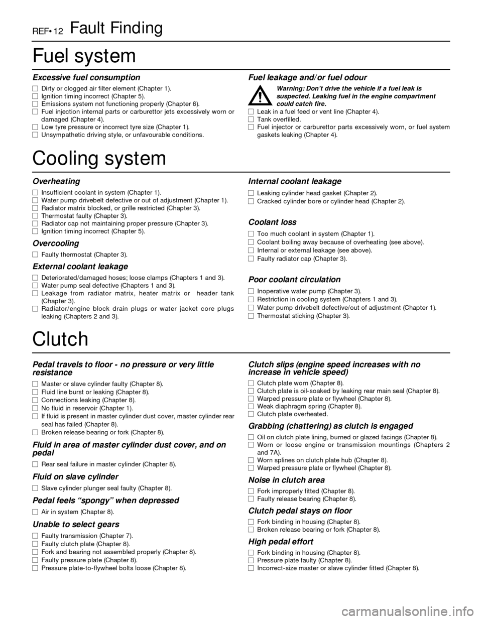
REF•12Fault Finding
Fuel system
Excessive fuel consumption
m mDirty or clogged air filter element (Chapter 1).
m mIgnition timing incorrect (Chapter 5).
m mEmissions system not functioning properly (Chapter 6).
m mFuel injection internal parts or carburettor jets excessively worn or
damaged (Chapter 4).
m mLow tyre pressure or incorrect tyre size (Chapter 1).
m mUnsympathetic driving style, or unfavourable conditions.
Fuel leakage and/or fuel odour
Warning: Don’t drive the vehicle if a fuel leak is
suspected. Leaking fuel in the engine compartment
could catch fire.
m mLeak in a fuel feed or vent line (Chapter 4).
m mTank overfilled.
m mFuel injector or carburettor parts excessively worn, or fuel system
gaskets leaking (Chapter 4).
Cooling system
Overheating
m mInsufficient coolant in system (Chapter 1).
m mWater pump drivebelt defective or out of adjustment (Chapter 1).
m mRadiator matrix blocked, or grille restricted (Chapter 3).
m mThermostat faulty (Chapter 3).
m mRadiator cap not maintaining proper pressure (Chapter 3).
m mIgnition timing incorrect (Chapter 5).
Overcooling
m
mFaulty thermostat (Chapter 3).
External coolant leakage
m
mDeteriorated/damaged hoses; loose clamps (Chapters 1 and 3).
m mWater pump seal defective (Chapters 1 and 3).
m mLeakage from radiator matrix, heater matrix or header tank
(Chapter 3).
m mRadiator/engine block drain plugs or water jacket core plugs
leaking (Chapters 2 and 3).
Internal coolant leakage
m mLeaking cylinder head gasket (Chapter 2).
m mCracked cylinder bore or cylinder head (Chapter 2).
Coolant loss
m
mToo much coolant in system (Chapter 1).
m mCoolant boiling away because of overheating (see above).
m mInternal or external leakage (see above).
m mFaulty radiator cap (Chapter 3).
Poor coolant circulation
m
mInoperative water pump (Chapter 3).
m mRestriction in cooling system (Chapters 1 and 3).
m mWater pump drivebelt defective/out of adjustment (Chapter 1).
m mThermostat sticking (Chapter 3).
Clutch
Pedal travels to floor - no pressure or very little
resistance
m mMaster or slave cylinder faulty (Chapter 8).
m mFluid line burst or leaking (Chapter 8).
m mConnections leaking (Chapter 8).
m mNo fluid in reservoir (Chapter 1).
m mIf fluid is present in master cylinder dust cover, master cylinder rear
seal has failed (Chapter 8).
m mBroken release bearing or fork (Chapter 8).
Fluid in area of master cylinder dust cover, and on
pedal
m mRear seal failure in master cylinder (Chapter 8).
Fluid on slave cylinder
m
mSlave cylinder plunger seal faulty (Chapter 8).
Pedal feels “spongy” when depressed
m
mAir in system (Chapter 8).
Unable to select gears
m
mFaulty transmission (Chapter 7).
m mFaulty clutch plate (Chapter 8).
m mFork and bearing not assembled properly (Chapter 8).
m mFaulty pressure plate (Chapter 8).
m mPressure plate-to-flywheel bolts loose (Chapter 8).
Clutch slips (engine speed increases with no
increase in vehicle speed)
m mClutch plate worn (Chapter 8).
m mClutch plate is oil-soaked by leaking rear main seal (Chapter 8).
m mWarped pressure plate or flywheel (Chapter 8).
m mWeak diaphragm spring (Chapter 8).
m mClutch plate overheated.
Grabbing (chattering) as clutch is engaged
m
mOil on clutch plate lining, burned or glazed facings (Chapter 8).
m mWorn or loose engine or transmission mountings (Chapters 2
and 7A).
m mWorn splines on clutch plate hub (Chapter 8).
m mWarped pressure plate or flywheel (Chapter 8).
Noise in clutch area
m
mFork improperly fitted (Chapter 8).
m mFaulty release bearing (Chapter 8).
Clutch pedal stays on floor
m
mFork binding in housing (Chapter 8).
m mBroken release bearing or fork (Chapter 8).
High pedal effort
m
mFork binding in housing (Chapter 8).
m mPressure plate faulty (Chapter 8).
m mIncorrect-size master or slave cylinder fitted (Chapter 8).