bolt BMW 3 SERIES 1985 E30 Manual PDF
[x] Cancel search | Manufacturer: BMW, Model Year: 1985, Model line: 3 SERIES, Model: BMW 3 SERIES 1985 E30Pages: 228, PDF Size: 7.04 MB
Page 119 of 228
Withdraw the sensor from its bracket and
remove it.
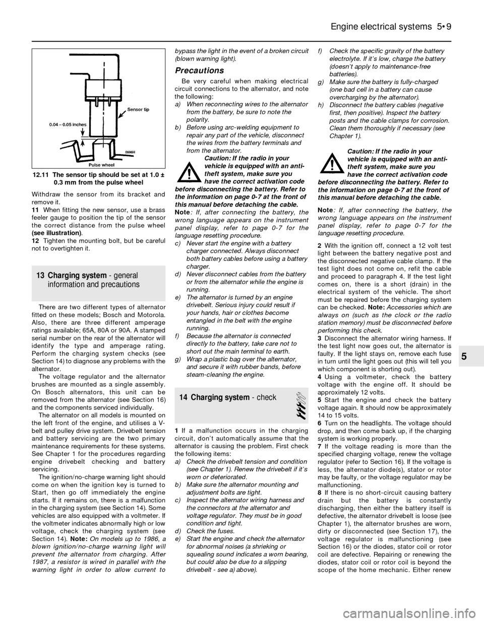
11When fitting the new sensor, use a brass
feeler gauge to position the tip of the sensor
the correct distance from the pulse wheel
(see illustration).
12Tighten the mounting bolt, but be careful
not to overtighten it.
13 Charging system- general
information and precautions
There are two different types of alternator
fitted on these models; Bosch and Motorola.
Also, there are three different amperage
ratings available; 65A, 80A or 90A. A stamped
serial number on the rear of the alternator will
identify the type and amperage rating.
Perform the charging system checks (see
Section 14) to diagnose any problems with the
alternator.
The voltage regulator and the alternator
brushes are mounted as a single assembly.
On Bosch alternators, this unit can be
removed from the alternator (see Section 16)
and the components serviced individually.
The alternator on all models is mounted on
the left front of the engine, and utilises a V-
belt and pulley drive system. Drivebelt tension
and battery servicing are the two primary
maintenance requirements for these systems.
See Chapter 1 for the procedures regarding
engine drivebelt checking and battery
servicing.
The ignition/no-charge warning light should
come on when the ignition key is turned to
Start, then go off immediately the engine
starts. If it remains on, there is a malfunction
in the charging system (see Section 14). Some
vehicles are also equipped with a voltmeter. If
the voltmeter indicates abnormally high or low
voltage, check the charging system (see
Section 14). Note:On models up to 1986, a
blown ignition/no-charge warning light will
prevent the alternator from charging. After
1987, a resistor is wired in parallel with the
warning light in order to allow current tobypass the light in the event of a broken circuit
(blown warning light).
Precautions
Be very careful when making electrical
circuit connections to the alternator, and note
the following:
a) When reconnecting wires to the alternator
from the battery, be sure to note the
polarity.
b) Before using arc-welding equipment to
repair any part of the vehicle, disconnect
the wires from the battery terminals and
from the alternator.
Caution: If the radio in your
vehicle is equipped with an anti-
theft system, make sure you
have the correct activation code
before disconnecting the battery. Refer to
the information on page 0-7 at the front of
this manual before detaching the cable.
Note: If, after connecting the battery, the
wrong language appears on the instrument
panel display, refer to page 0-7 for the
language resetting procedure.
c) Never start the engine with a battery
charger connected. Always disconnect
both battery cables before using a battery
charger.
d) Never disconnect cables from the battery
or from the alternator while the engine is
running.
e) The alternator is turned by an engine
drivebelt. Serious injury could result if
your hands, hair or clothes become
entangled in the belt with the engine
running.
f) Because the alternator is connected
directly to the battery, take care not to
short out the main terminal to earth.
g) Wrap a plastic bag over the alternator,
and secure it with rubber bands, before
steam-cleaning the engine.
14 Charging system- check
3
1If a malfunction occurs in the charging
circuit, don’t automatically assume that the
alternator is causing the problem. First check
the following items:
a) Check the drivebelt tension and condition
(see Chapter 1). Renew the drivebelt if it’s
worn or deteriorated.
b) Make sure the alternator mounting and
adjustment bolts are tight.
c) Inspect the alternator wiring harness and
the connectors at the alternator and
voltage regulator. They must be in good
condition and tight.
d) Check the fuses.
e) Start the engine and check the alternator
for abnormal noises (a shrieking or
squealing sound indicates a worn bearing,
but could also be due to a slipping
drivebelt - see a) above).f) Check the specific gravity of the battery
electrolyte. If it’s low, charge the battery
(doesn’t apply to maintenance-free
batteries).
g) Make sure the battery is fully-charged
(one bad cell in a battery can cause
overcharging by the alternator).
h) Disconnect the battery cables (negative
first, then positive). Inspect the battery
posts and the cable clamps for corrosion.
Clean them thoroughly if necessary (see
Chapter 1).
Caution: If the radio in your
vehicle is equipped with an anti-
theft system, make sure you
have the correct activation code
before disconnecting the battery. Refer to
the information on page 0-7 at the front of
this manual before detaching the cable.
Note: If, after connecting the battery, the
wrong language appears on the instrument
panel display, refer to page 0-7 for the
language resetting procedure.
2With the ignition off, connect a 12 volt test
light between the battery negative post and
the disconnected negative cable clamp. If the
test light does not come on, refit the cable
and proceed to paragraph 4. If the test light
comes on, there is a short (drain) in the
electrical system of the vehicle. The short
must be repaired before the charging system
can be checked. Note: Accessories which are
always on (such as the clock or the radio
station memory) must be disconnected before
performing this check.
3Disconnect the alternator wiring harness. If
the test light now goes out, the alternator is
faulty. If the light stays on, remove each fuse
in turn until the light goes out (this will tell you
which component is shorting out).
4Using a voltmeter, check the battery
voltage with the engine off. It should be
approximately 12 volts.
5Start the engine and check the battery
voltage again. It should now be approximately
14 to 15 volts.
6Turn on the headlights. The voltage should
drop, and then come back up, if the charging
system is working properly.
7If the voltage reading is more than the
specified charging voltage, renew the voltage
regulator (refer to Section 16). If the voltage is
less, the alternator diode(s), stator or rotor
may be faulty, or the voltage regulator may be
malfunctioning.
8If there is no short-circuit causing battery
drain but the battery is constantly
discharging, then either the battery itself is
defective, the alternator drivebelt is loose (see
Chapter 1), the alternator brushes are worn,
dirty or disconnected (see Section 17), the
voltage regulator is malfunctioning (see
Section 16) or the diodes, stator coil or rotor
coil are defective. Repairing or renewing the
diodes, stator coil or rotor coil is beyond the
scope of the home mechanic. Either renew
Engine electrical systems 5•9
12.11 The sensor tip should be set at 1.0 ±
0.3 mm from the pulse wheel
5
Page 120 of 228
the alternator complete, or take it to an
automotive electrician, who may be able to
overhaul it. Note:On models up to 1986, a
blown ignition/no-charge warning light bulb
will prevent the alternator from charging. After
1987, a resistor is wired in parallel with the
warning light, in order to allow current to
bypass the light in the event of a broken circuit
(blown warning light).
15 Alternator-
removal and refitting
1
Caution: If the radio in your
vehicle is equipped with an anti-
theft system, make sure you
have the correct activation code
before disconnecting the battery. Refer to
the information on page 0-7 at the front of
this manual before detaching the cable.
Note: If, after connecting the battery, the
wrong language appears on the instrument
panel display, refer to page 0-7 for the
language resetting procedure.
Removal
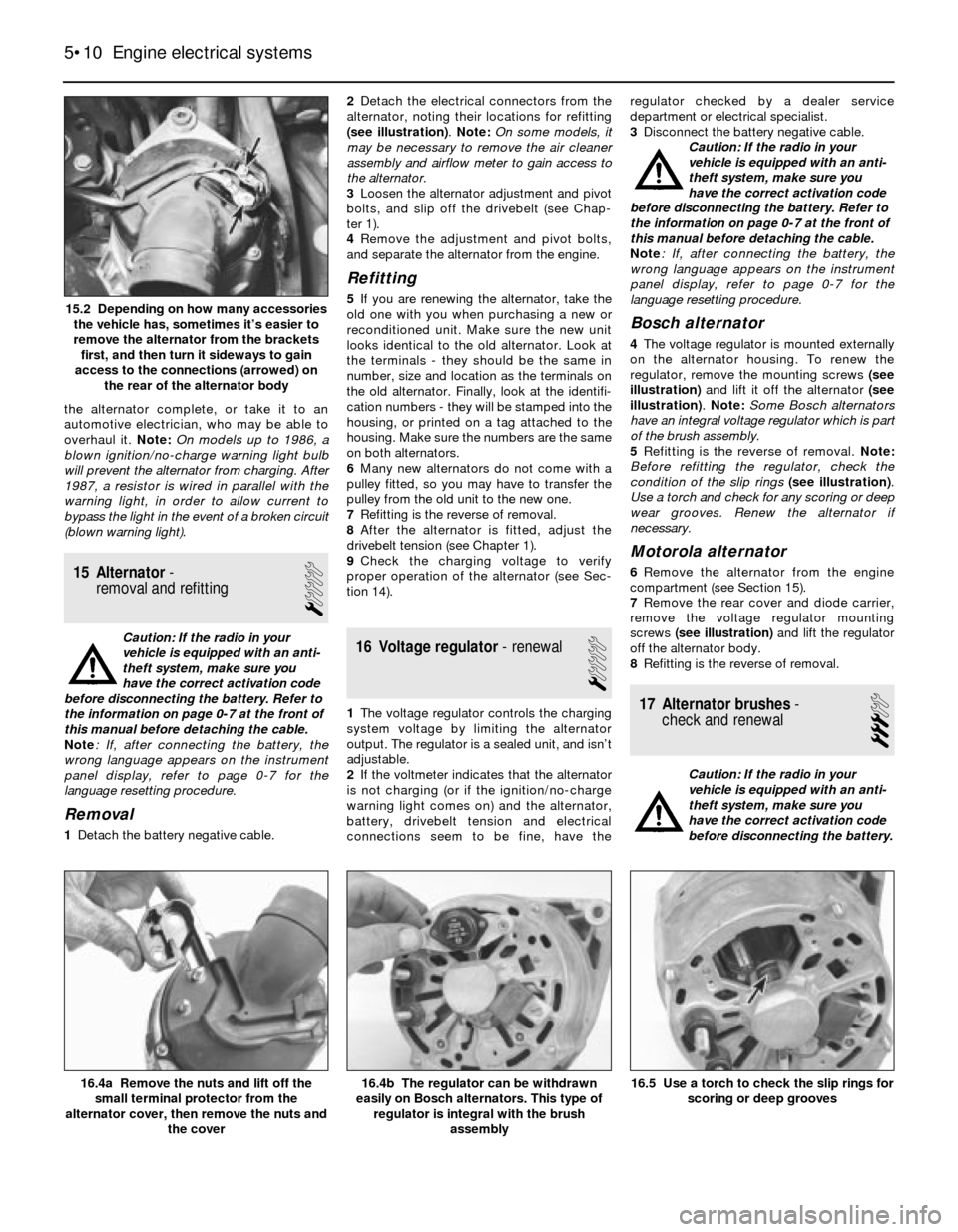
1Detach the battery negative cable.2Detach the electrical connectors from the
alternator, noting their locations for refitting
(see illustration). Note: On some models, it
may be necessary to remove the air cleaner
assembly and airflow meter to gain access to
the alternator.
3Loosen the alternator adjustment and pivot
bolts, and slip off the drivebelt (see Chap-
ter 1).
4Remove the adjustment and pivot bolts,
and separate the alternator from the engine.
Refitting
5If you are renewing the alternator, take the
old one with you when purchasing a new or
reconditioned unit. Make sure the new unit
looks identical to the old alternator. Look at
the terminals - they should be the same in
number, size and location as the terminals on
the old alternator. Finally, look at the identifi-
cation numbers - they will be stamped into the
housing, or printed on a tag attached to the
housing. Make sure the numbers are the same
on both alternators.
6Many new alternators do not come with a
pulley fitted, so you may have to transfer the
pulley from the old unit to the new one.
7Refitting is the reverse of removal.
8After the alternator is fitted, adjust the
drivebelt tension (see Chapter 1).
9Check the charging voltage to verify
proper operation of the alternator (see Sec-
tion 14).
16 Voltage regulator- renewal
1
1The voltage regulator controls the charging
system voltage by limiting the alternator
output. The regulator is a sealed unit, and isn’t
adjustable.
2If the voltmeter indicates that the alternator
is not charging (or if the ignition/no-charge
warning light comes on) and the alternator,
battery, drivebelt tension and electrical
connections seem to be fine, have theregulator checked by a dealer service
department or electrical specialist.
3Disconnect the battery negative cable.
Caution: If the radio in your
vehicle is equipped with an anti-
theft system, make sure you
have the correct activation code
before disconnecting the battery. Refer to
the information on page 0-7 at the front of
this manual before detaching the cable.
Note: If, after connecting the battery, the
wrong language appears on the instrument
panel display, refer to page 0-7 for the
language resetting procedure.
Bosch alternator
4The voltage regulator is mounted externally
on the alternator housing. To renew the
regulator, remove the mounting screws (see
illustration)and lift it off the alternator (see
illustration). Note: Some Bosch alternators
have an integral voltage regulator which is part
of the brush assembly.
5Refitting is the reverse of removal. Note:
Before refitting the regulator, check the
condition of the slip rings(see illustration).
Use a torch and check for any scoring or deep
wear grooves. Renew the alternator if
necessary.
Motorola alternator
6Remove the alternator from the engine
compartment (see Section 15).
7Remove the rear cover and diode carrier,
remove the voltage regulator mounting
screws (see illustration)and lift the regulator
off the alternator body.
8Refitting is the reverse of removal.
17 Alternator brushes-
check and renewal
3
Caution: If the radio in your
vehicle is equipped with an anti-
theft system, make sure you
have the correct activation code
before disconnecting the battery.
5•10 Engine electrical systems
16.5 Use a torch to check the slip rings for
scoring or deep grooves16.4b The regulator can be withdrawn
easily on Bosch alternators. This type of
regulator is integral with the brush
assembly16.4a Remove the nuts and lift off the
small terminal protector from the
alternator cover, then remove the nuts and
the cover
15.2 Depending on how many accessories
the vehicle has, sometimes it’s easier to
remove the alternator from the brackets
first, and then turn it sideways to gain
access to the connections (arrowed) on
the rear of the alternator body
Page 122 of 228
when the transmission selector lever is in Park
or Neutral.
Always detach the battery negative cable
before working on the starting system.
19 Starter motor-
in-vehicle check
2
Note:Before diagnosing starter problems,
make sure the battery is fully charged.
1If the starter motor does not turn at all when
the switch is operated, make sure that the
gear lever is in Neutral or Park (automatic
transmission) or, where applicable, that the
clutch pedal is depressed (manual
transmission).
2Make sure that the battery is charged, and
that all cables, both at the battery and starter
solenoid terminals, are clean and secure.
3If the starter motor spins but the engine is
not cranking, the overrun clutch in the starter
motor is slipping, and the starter motor must
be renewed.
4If, when the switch is actuated, the starter
motor does not operate at all but the solenoid
clicks, then the problem lies either in the
battery, the main solenoid contacts, or the
starter motor itself (or the engine is seized).
5If the solenoid plunger cannot be heard
when the switch is actuated, the battery is
faulty, the switch is defective, the fusible link
is burned-out (the circuit is open), or the
solenoid itself is defective.
6To check the solenoid, connect a jumper
lead between the battery (+) and the ignition
switch wire terminal (the small terminal) on the
solenoid. If the starter motor now operates,
the solenoid is OK and the problem is in the
ignition switch, starter inhibitor switch
(automatic transmission models), clutch
switch (some manual transmission models), or
the wiring.
7If the starter motor still does not operate,
remove the starter/solenoid assembly for
dismantling, testing and repair.
8If the starter motor cranks the engine at an
abnormally-slow speed, first make sure that
the battery is charged, and that all terminal
connections are tight. If the engine is partially-
seized, or has the wrong viscosity oil in it, it
will crank slowly.
9Run the engine until normal operating
temperature is reached, then disconnect the
coil HT lead from the distributor cap and earth
it on the engine.
10Connect a voltmeter positive lead to the
battery positive post, and connect the
negative lead to the negative post.11Crank the engine, and take the voltmeter
readings as soon as a steady figure is
indicated. Do not allow the starter motor to
turn for more than 10 seconds at a time. A
reading of 9 volts or more, with the starter
motor turning at normal cranking speed, is
normal. If the reading is 9 volts or more but
the cranking speed is slow, the solenoid
contacts are burned, there is a bad
connection, or the starter motor itself is faulty.
If the reading is less than 9 volts and the
cranking speed is slow, the starter motor is
faulty or the battery is responsible (defective
or discharged).
20 Starter motor-
removal and refitting
1
Note:If the starter motor is defective, it should
be renewed, or taken to an auto electrical
specialist for repair. Overhaul of the starter
motor is unlikely to be a practical proposition
for the home mechanic, even if spare parts are
available. However, the solenoid can be
renewed separately (see Section 21).
Removal
Caution: If the radio in your
vehicle is equipped with an anti-
theft system, make sure you
have the correct activation code
before disconnecting the battery. Refer to
the information on page 0-7 at the front of
this manual before detaching the cable.
Note: If, after connecting the battery, the
wrong language appears on the instrument
panel display, refer to page 0-7 for the
language resetting procedure.
1Detach the battery negative cable.
2Raise the vehicle and support it securely on
axle stands.
3Clearly label the wires from the terminals onthe starter motor and solenoid, then
disconnect them. Note: On some models, it
may be necessary to remove the air cleaner
(see Chapter 4), coolant expansion tank (see
Chapter 3) and the heater hoses to gain
access to the top of the starter. Carefully label
any hoses or components that need to be
removed from the engine compartment, to
avoid confusion when reassembling.
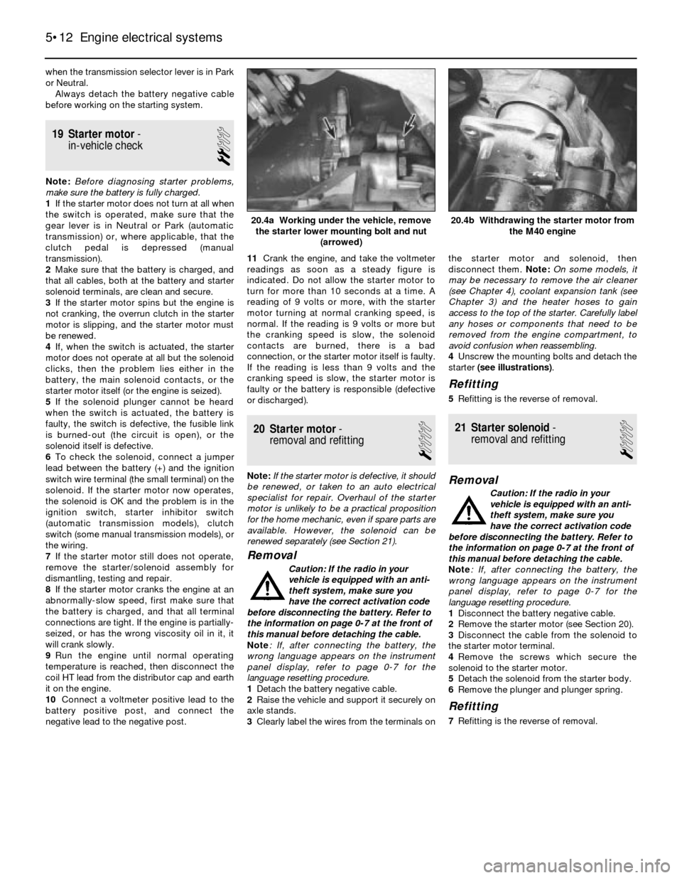
4Unscrew the mounting bolts and detach the
starter (see illustrations).
Refitting
5Refitting is the reverse of removal.
21 Starter solenoid-
removal and refitting
1
Removal
Caution: If the radio in your
vehicle is equipped with an anti-
theft system, make sure you
have the correct activation code
before disconnecting the battery. Refer to
the information on page 0-7 at the front of
this manual before detaching the cable.
Note: If, after connecting the battery, the
wrong language appears on the instrument
panel display, refer to page 0-7 for the
language resetting procedure.
1Disconnect the battery negative cable.
2Remove the starter motor (see Section 20).
3Disconnect the cable from the solenoid to
the starter motor terminal.
4Remove the screws which secure the
solenoid to the starter motor.
5Detach the solenoid from the starter body.
6Remove the plunger and plunger spring.
Refitting
7Refitting is the reverse of removal.
5•12 Engine electrical systems
20.4b Withdrawing the starter motor from
the M40 engine20.4a Working under the vehicle, remove
the starter lower mounting bolt and nut
(arrowed)
Page 123 of 228
6
Chapter 6
Engine management and emission control systems
Catalytic converter . . . . . . . . . . . . . . . . . . . . . . . . . . . . . . . . . . . . . . 7
Electronic Control Unit (ECU) - removal and refitting . . . . . . . . . . . . 3
Evaporative emissions control (EVAP) system . . . . . . . . . . . . . . . . . 6
Evaporative emissions control system inspection . . . See Chapter 1
General information . . . . . . . . . . . . . . . . . . . . . . . . . . . . . . . . . . . . . . 1Information sensors . . . . . . . . . . . . . . . . . . . . . . . . . . . . . . . . . . . . . . 4
Motronic engine management system self-diagnosis -
general information . . . . . . . . . . . . . . . . . . . . . . . . . . . . . . . . . . . . 2
Positive crankcase ventilation (PCV) system . . . . . . . . . . . . . . . . . . 5
6•1
Easy,suitable for
novice with little
experienceFairly easy,suitable
for beginner with
some experienceFairly difficult,
suitable for competent
DIY mechanic
Difficult,suitable for
experienced DIY
mechanicVery difficult,
suitable for expert
DIY or professional
Degrees of difficulty Contents
1 General information
To prevent pollution of the atmosphere
from incomplete combustion or evaporation
of the fuel, and to maintain good driveability
and fuel economy, a number of emission
control systems are used on these vehicles.
Not all of these systems are fitted to all
models, but they include the following:
Catalytic converter
Evaporative emission control (EVAP) system
Positive crankcase ventilation (PCV) system
Electronic engine management
The Sections in this Chapter include
general descriptions and checking
procedures within the scope of the home
mechanic, as well as component renewal
procedures (when possible) for each of the
systems listed above.
Before assuming that an emissions control
system is malfunctioning, check the fuel and
ignition systems carefully. The diagnosis of
some emission control devices requires
specialised tools, equipment and training. If
checking and servicing become too difficult,
or if a procedure is beyond your ability,
consult a dealer service department or other
specialist.This doesn’t mean, however, that emission
control systems are particularly difficult to
maintain and repair. You can quickly and
easily perform many checks, and do most of
the regular maintenance at home with
common tune-up and hand tools.
Pay close attention to any special
precautions outlined in this Chapter. It should
be noted that the illustrations of the various
systems may not exactly match the system
fitted on your vehicle because of
changes made by the manufacturer during
production.
2 Motronic engine management
system self-diagnosis-
general information
The Motronic engine management system
control unit (computer) has a built-in self-
diagnosis system, which detects malfunctions
in the system sensors and stores them as
fault codes in its memory. It is not possible
without dedicated test equipment to extract
these fault codes from the control unit.
However, the procedures given in Chapters 4
and 5 may be used to check individual
components and sensors of the Motronic
system. If this fails to pinpoint a fault, then the
vehicle should be taken to a BMW dealer, who
will have the necessary diagnostic
equipment to call up the fault codes from the
control unit. You will then have the
option to repair the fault yourself, or
alternatively have the fault repaired by the
BMW dealer.
3 Electronic control unit (ECU)
- removal and refitting
2
Removal
1The Electronic Control Unit (ECU) is located
either inside the passenger compartment
under the right-hand side of the facia panel on
3-Series models, or in the engine
compartment on the right-hand side on 5-
Series models (see Chapter 4).
2Disconnect the battery negative cable.
Caution: If the radio in your
vehicle is equipped with an anti-
theft system, make sure you
have the correct activation code
before disconnecting the battery. Refer to
the information on page 0-7 at the front of
this manual before detaching the cable.
Note: If, after connecting the battery, the
wrong language appears on the instrument
panel display, refer to page 0-7 for the
language resetting procedure.
3First remove the access cover on models
with the ECU on the right-hand side of the
engine compartment (see Chapter 4).
4If the ECU is located inside the vehicle,
remove the access cover on the right-hand side.
5Unplug the electrical connectors from the
ECU.
6Remove the retaining bolts from the ECU
bracket.
7Carefully remove the ECU. Note: Avoid static
electricity damage to the ECU by wearing rubber
gloves, and do not touch the connector pins.
Refitting
8Refitting is a reversal of removal.
The most frequent cause of
emission system problems is
simply a leaking vacuum hose
or loose wire, so always
check the hose and wiring connections
first.
Page 128 of 228
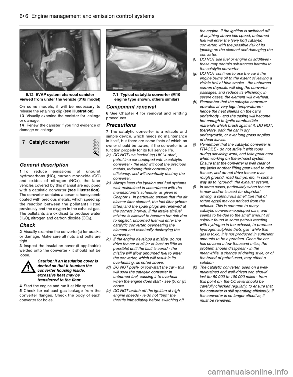
On some models, it will be necessary to
release the retaining clip (see illustration).
13Visually examine the canister for leakage
or damage.
14Renew the canister if you find evidence of
damage or leakage.
7 Catalytic converter
1
General description
1To reduce emissions of unburnt
hydrocarbons (HC), carbon monoxide (CO)
and oxides of nitrogen (NOx), the later
vehicles covered by this manual are equipped
with a catalytic converter (see illustration).
The converter contains a ceramic honeycomb
coated with precious metals, which speed up
the reaction between the pollutants listed
previously and the oxygen in the exhaust gas.
The pollutants are oxidised to produce water
(H
2O), nitrogen and carbon dioxide (CO2).
Check
2Visually examine the converter(s) for cracks
or damage. Make sure all nuts and bolts are
tight.
3Inspect the insulation cover (if applicable)
welded onto the converter - it should not be
loose.
Caution: If an insulation cover is
dented so that it touches the
converter housing inside,
excessive heat may be
transferred to the floor.
4Start the engine and run it at idle speed.
5Check for exhaust gas leakage from the
converter flanges. Check the body of each
converter for holes.
Component renewal
6See Chapter 4 for removal and refitting
procedures.
Precautions
7The catalytic converter is a reliable and
simple device, which needs no maintenance
in itself, but there are some facts of which an
owner should be aware, if the converter is to
function properly for its full service life.
(a) DO NOT use leaded (eg UK “4-star”)
petrol in a car equipped with a catalytic
converter - the lead will coat the precious
metals, reducing their converting
efficiency, and will eventually destroy the
converter.
(b) Always keep the ignition and fuel systems
well-maintained in accordance with the
manufacturer’s schedule, as given in
Chapter 1. In particular, ensure that the air
cleaner filter element, the fuel filter (where
fitted) and the spark plugs are renewed at
the correct interval. If the intake air/fuel
mixture is allowed to become too rich due
to neglect, unburned fuel will enter the
catalytic converter, overheating the
element and eventually destroying the
converter.
(c) If the engine develops a misfire, do not
drive the car at all (or at least as little as
possible) until the fault is cured - the
misfire will allow unburned fuel to enter
the converter, which will result in its
overheating, as noted above.
(d) DO NOT push- or tow-start the car - this
will soak the catalytic converter in
unburned fuel, causing it to overheat
when the engine does start - see (b) or (c)
above.
(e) DO NOT switch off the ignition at high
engine speeds - ie do not “blip” the
throttle immediately before switching offthe engine. If the ignition is switched off
at anything above idle speed, unburned
fuel will enter the (very hot) catalytic
converter, with the possible risk of its
igniting on the element and damaging the
converter.
(f) DO NOT use fuel or engine oil additives -
these may contain substances harmful to
the catalytic converter.
(g) DO NOT continue to use the car if the
engine burns oil to the extent of leaving a
visible trail of blue smoke - the unburned
carbon deposits will clog the converter
passages, and reduce its efficiency; in
severe cases, the element will overheat.
(h) Remember that the catalytic converter
operates at very high temperatures -
hence the heat shields on the car’s
underbody - and the casing will become
hot enough to ignite combustible
materials which brush against it. DO NOT,
therefore, park the car in dry
undergrowth, or over long grass or piles
of dead leaves.
(i) Remember that the catalytic converter is
FRAGILE - do not strike it with tools
during servicing work, and take great care
when working on the exhaust system.
Ensure that the converter is well clear of
any jacks or other lifting gear used to raise
the car, and do not drive the car over
rough ground, road humps, etc, in such a
way as to “ground” the exhaust system.
(j) In some cases, particularly when the car
is new and/or is used for stop/start
driving, a sulphurous smell (like that of
rotten eggs) may be noticed from the
exhaust. This is common to many
catalytic converter-equipped cars, and
seems to be due to the small amount of
sulphur found in some petrols reacting
with hydrogen in the exhaust, to produce
hydrogen sulphide (H
2S) gas; while this
gas is toxic, it is not produced in sufficient
amounts to be a problem. Once the car
has covered a few thousand miles, the
problem should disappear - in the
meanwhile, a change of driving style, or of
the brand of petrol used, may effect a
solution.
(k) The catalytic converter, used on a well-
maintained and well-driven car, should
last for 50 000 to 100 000 miles - from
this point on, the CO level should be
carefully checked regularly, to ensure that
the converter is still operating efficiently. If
the converter is no longer effective, it
must be renewed.
6•6 Engine management and emission control systems
7.1 Typical catalytic converter (M10
engine type shown, others similar)6.12 EVAP system charcoal canister
viewed from under the vehicle (316i model)
Page 130 of 228
Torque wrench settingsNm
Front disc brake caliper
Caliper guide (mounting) bolts . . . . . . . . . . . . . . . . . . . . . . . . . . . . . . 30 to 35
Caliper bracket-to-strut housing bolts
3-Series, E30 . . . . . . . . . . . . . . . . . . . . . . . . . . . . . . . . . . . . . . . . . . 123
5-Series, E28 (“old-shape”) . . . . . . . . . . . . . . . . . . . . . . . . . . . . . . . 123
5-Series, E34 (“new-shape”) . . . . . . . . . . . . . . . . . . . . . . . . . . . . . . 110
Rear disc brake caliper
Caliper guide (mounting) bolts . . . . . . . . . . . . . . . . . . . . . . . . . . . . . . 30 to 35
Carrier-to-trailing arm bolts . . . . . . . . . . . . . . . . . . . . . . . . . . . . . . . . 67
Brake hose-to-caliper fitting . . . . . . . . . . . . . . . . . . . . . . . . . . . . . . . . . . 14 to 17
Master cylinder-to-brake servo nuts
3-Series . . . . . . . . . . . . . . . . . . . . . . . . . . . . . . . . . . . . . . . . . . . . . . . . 24
5-Series . . . . . . . . . . . . . . . . . . . . . . . . . . . . . . . . . . . . . . . . . . . . . . . . 25 to 29
Brake servo mounting nuts . . . . . . . . . . . . . . . . . . . . . . . . . . . . . . . . . . . 22 to 24
Hydraulic line-to-hydraulic brake servo threaded
fittings - 5-Series, E28 (“old-shape”) . . . . . . . . . . . . . . . . . . . . . . . . . . . 31
Wheel bolts . . . . . . . . . . . . . . . . . . . . . . . . . . . . . . . . . . . . . . . . . . . . . . . See Chapter 1
9•2 Braking system
1 General information
All 3-Series models, and 5-Series E28 (“old-
shape”) models, are equipped with front disc
brakes and either rear drum or rear disc
brakes. 5-Series E34 (“new-shape”) models
have disc brakes front and rear. Front and
rear brakes are self-adjusting on all models.
Some later models are equipped with an Anti-
lock Braking System (ABS); this is described
in Section 2.
Hydraulic system
The hydraulic system consists of two
separate circuits. The master cylinder has
separate reservoirs for the two circuits; in the
event of a leak or failure in one hydraulic
circuit, the other circuit will remain operative.
Brake servo
The vacuum brake servo, utilising engine
manifold vacuum and atmospheric pressure
to provide assistance to the hydraulically
operated brakes, is mounted on the bulkhead
in the engine compartment.
A hydraulic brake servo system is used on
5-Series E28 models. This system uses
hydraulic pressure from the power steering
pump to assist braking.
Handbrake
The handbrake operates the rear brakes,
and is cable-operated via a lever mounted in
the centre console. The handbrake assembly
on rear drum brake models is part of the rear
drum brake assembly, and is self-adjusting.
On rear disc brake models, the handbrake
uses a pair of brake shoes located inside the
centre portion of the rear brake disc, and is
manually-adjusted.
Brake pad wear warning system
The brake pad wear warning system is
linked to a red warning light in the instrumentcluster, which comes on when the brake pads
have worn down to the point at which they
require renewal. DO NOT ignore this reminder.
If you don’t renew the pads shortly after the
brake pad wear warning light comes on, the
brake discs will be damaged.
On some models, the brake pad wear
warning system also includes an early
warning light that comes on only when the
brake pedal is depressed, letting you know in
advance that the pads need to be renewed.
The wear sensor is attached to the brake
pads. The sensor is located at the left front
wheel; on some models, there is another
sensor at the right rear wheel. The wear
sensor is part of a closed circuit. Once the
pads wear down to the point at which they’re
flush with the sensor, the disc grinds away the
side of the sensor facing the disc. Thus, the
wire inside the sensor is broken, and the red
light on the instrument panel comes on.
Always check the sensor(s) when renewing
the pads. If you change the pads before the
warning light comes on, the sensor(s) may still
be good; once the light has come on, renew
the sensor.
Service
After completing any operation involving
dismantling of any part of the brake system,
always test drive the vehicle to check for
proper braking performance before resuming
normal driving. When testing the brakes, try to
select a clean, dry, road with no camber (ie as
flat as possible) and with no other traffic.
Conditions other than these can lead to
inaccurate test results.
Test the brakes at various speeds with both
light and heavy pedal pressure. The vehicle
should stop evenly, without pulling to one side
or the other. Avoid locking the brakes,
because this slides the tyres and diminishes
braking efficiency and control of the vehicle.
Tyres, vehicle load and wheel alignment are
factors which also affect braking
performance.
2 Anti-lock Braking system
(ABS)- general information
The Anti-lock Braking System is designed
to maintain vehicle control, directional stability
and optimum deceleration under severe
braking conditions on most road surfaces. It
does so by monitoring the rotational speed of
each wheel and controlling the brake line
pressure to each wheel during braking. This
prevents the wheels from locking up.
The ABS system has three main
components - the wheel speed sensors, the
electronic control unit, and the hydraulic
control unit. The sensors - one at each wheel
since 1985, but at both front wheels and one
at the rear differential on earlier models - send
a variable voltage signal to the control unit,
which monitors these signals, compares them
to its program information, and determines
whether a wheel is about to lock up. When a
wheel is about to lock up, the control unit
signals the hydraulic unit to reduce hydraulic
pressure (or not increase it further) at that
wheel’s brake caliper. Pressure modulation is
handled by electrically-operated solenoid
valves.
If a problem develops within the system, an
“ABS” warning light will glow on the
dashboard. Sometimes, a visual inspection of
the ABS system can help you locate the
problem. Carefully inspect the ABS wiring
harness. Pay particularly close attention to the
harness and connections near each wheel.
Look for signs of chafing and other damage
caused by incorrectly-routed wires. If a wheel
sensor harness is damaged, the sensor
should be renewed (the harness and sensor
are integral).
Warning: DO NOT try to repair an
ABS wiring harness. The ABS
system is sensitive to even the
smallest changes in resistance. Repairing
the harness could alter resistance values
Page 131 of 228
and cause the system to malfunction. If
the ABS wiring harness is damaged in any
way, it must be renewed.
Caution: Make sure the ignition is
turned off before unplugging or
re-making any electrical
connections.
Diagnosis and repair
If the dashboard warning light comes on
and stays on while the vehicle is in operation,
the ABS system requires attention. Although
special electronic ABS diagnostic testing
tools are necessary to properly diagnose the
system, you can perform a few preliminary
checks before taking the vehicle to a dealer
service department.
a) Check the brake fluid level in the
reservoir.
b) Verify that the electronic control unit
connectors are securely connected.
c) Check the electrical connectors at the
hydraulic control unit.
d) Check the fuses.
e) Follow the wiring harness to each front
and rear wheel, and verify that all
connections are secure and that the
wiring is undamaged.
If the above preliminary checks do not
rectify the problem, the vehicle should bediagnosed by a dealer service department.
Due to the complex nature of this system, all
actual repair work must be done by a dealer
service department.
3 Disc brake pads- renewal
2
Warning: Disc brake pads must
be renewed on both front wheels
or both rear wheels at the same
time - NEVER renew the pads on
only one wheel. Also, the dust created by
the brake system may contain asbestos,
which is harmful to your health. Never
blow it out with compressed air, and don’t
inhale any of it. An approved filtering mask
should be worn when working on the
brakes. Do not, under any circumstances,
use petroleum-based solvents to clean
brake parts. Use brake system cleaner
only! When servicing the disc brakes, use
only original-equipment or high-quality
brand-name pads.
Warning: Brake fluid is
poisonous. It is also an effective
paint stripper. Refer to the
warning at the start of Section 16.
Note:This procedure applies to both the front
and rear disc brakes.
1Remove the cap(s) from the brake fluid
reservoir, and syphon off about two-thirds of
the fluid from the reservoir. Failing to do thiscould result in the reservoir overflowing when
the caliper pistons are pressed back into their
bores.
2Loosen the wheel bolts, raise the front or
rear of the vehicle and support it securely on
axle stands.
3Remove the front or rear wheels, as
applicable. Work on one brake assembly at a
time, using the assembled brake for reference
if necessary.
4Inspect the brake disc carefully as outlined
in Section 5. If machining is necessary, follow
the information in that Section to remove the
disc, at which time the pads can be removed
from the calipers as well.
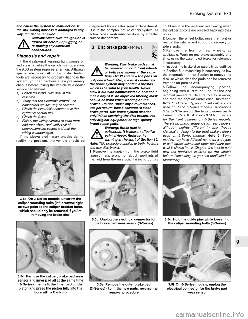
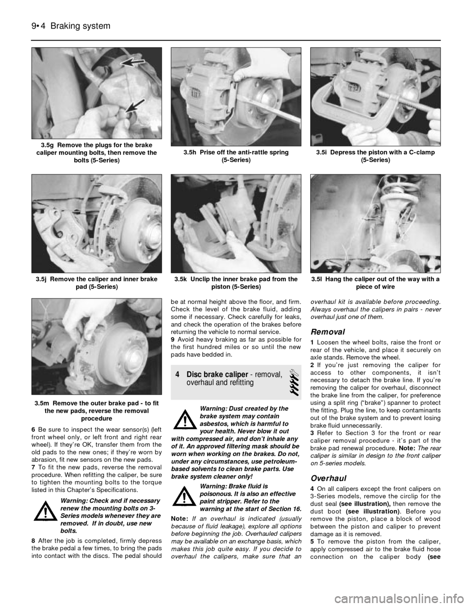
5Follow the accompanying photos,
beginning with illustration 3.5a, for the pad
removal procedure. Be sure to stay in order,
and read the caption under each illustration.
Note 1:Different types of front calipers are
used on 3 and 5-Series models. Illustrations
3.5a to 3.5e are for the front calipers on 3-
Series models.Illustrations 3.5f to 3.5m are
for the front calipers on 5-Series models.
There’s no photo sequence for rear calipers;
although slightly different in size, they’re
identical in design to the front brake calipers
used on 5-Series models.Note 2: Some
models may have different numbers and types
of anti-squeal shims and other hardware than
what is shown in this Chapter. It’s best to note
how the hardware is fitted on the vehicle
before dismantling, so you can duplicate it on
reassembly.
Braking system 9•3
3.5c Hold the guide pins while loosening
the caliper mounting bolts (3-Series)3.5b Unplug the electrical connector for
the brake pad wear sensor (3-Series)
3.5a On 3-Series models, unscrew the
caliper mounting bolts (left arrows); right
arrows point to the caliper bracket bolts,
which should only be removed if you’re
removing the brake disc
3.5f On 5-Series models, unplug the
electrical connector for the brake pad
wear sensor3.5e Remove the outer brake pad
(3-Series) - to fit the new pads, reverse the
removal procedure
3.5d Remove the caliper, brake pad wear
sensor and inner pad all at the same time
(3-Series), then refit the inner pad on the
piston and press the piston fully into the
bore with a C-clamp
9
Page 132 of 228
6Be sure to inspect the wear sensor(s) (left
front wheel only, or left front and right rear
wheel). If they’re OK, transfer them from the
old pads to the new ones; if they’re worn by
abrasion, fit new sensors on the new pads.
7To fit the new pads, reverse the removal
procedure. When refitting the caliper, be sure
to tighten the mounting bolts to the torque
listed in this Chapter’s Specifications.
Warning: Check and if necessary
renew the mounting bolts on 3-
Series models whenever they are
removed. If in doubt, use new
bolts.
8After the job is completed, firmly depress
the brake pedal a few times, to bring the pads
into contact with the discs. The pedal shouldbe at normal height above the floor, and firm.
Check the level of the brake fluid, adding
some if necessary. Check carefully for leaks,
and check the operation of the brakes before
returning the vehicle to normal service.
9Avoid heavy braking as far as possible for
the first hundred miles or so until the new
pads have bedded in.
4 Disc brake caliper- removal,
overhaul and refitting
4
Warning: Dust created by the
brake system may contain
asbestos, which is harmful to
your health. Never blow it out
with compressed air, and don’t inhale any
of it. An approved filtering mask should be
worn when working on the brakes. Do not,
under any circumstances, use petroleum-
based solvents to clean brake parts. Use
brake system cleaner only!
Warning: Brake fluid is
poisonous. It is also an effective
paint stripper. Refer to the
warning at the start of Section 16.
Note:If an overhaul is indicated (usually
because of fluid leakage), explore all options
before beginning the job. Overhauled calipers
may be available on an exchange basis, which
makes this job quite easy. If you decide to
overhaul the calipers, make sure that anoverhaul kit is available before proceeding.
Always overhaul the calipers in pairs - never
overhaul just one of them.
Removal
1Loosen the wheel bolts, raise the front or
rear of the vehicle, and place it securely on
axle stands. Remove the wheel.
2If you’re just removing the caliper for
access to other components, it isn’t
necessary to detach the brake line. If you’re
removing the caliper for overhaul, disconnect
the brake line from the caliper, for preference
using a split ring (“brake”) spanner to protect
the fitting. Plug the line, to keep contaminants
out of the brake system and to prevent losing
brake fluid unnecessarily.
3Refer to Section 3 for the front or rear
caliper removal procedure - it’s part of the
brake pad renewal procedure. Note:The rear
caliper is similar in design to the front caliper
on 5-series models.
Overhaul
4On all calipers except the front calipers on
3-Series models, remove the circlip for the
dust seal (see illustration),then remove the
dust boot (see illustration). Before you
remove the piston, place a block of wood
between the piston and caliper to prevent
damage as it is removed.
5To remove the piston from the caliper,
apply compressed air to the brake fluid hose
connection on the caliper body (see
9•4 Braking system
3.5l Hang the caliper out of the way with a
piece of wire
3.5m Remove the outer brake pad - to fit
the new pads, reverse the removal
procedure
3.5k Unclip the inner brake pad from the
piston (5-Series)3.5j Remove the caliper and inner brake
pad (5-Series)
3.5i Depress the piston with a C-clamp
(5-Series)3.5h Prise off the anti-rattle spring
(5-Series)3.5g Remove the plugs for the brake
caliper mounting bolts, then remove the
bolts (5-Series)
Page 133 of 228
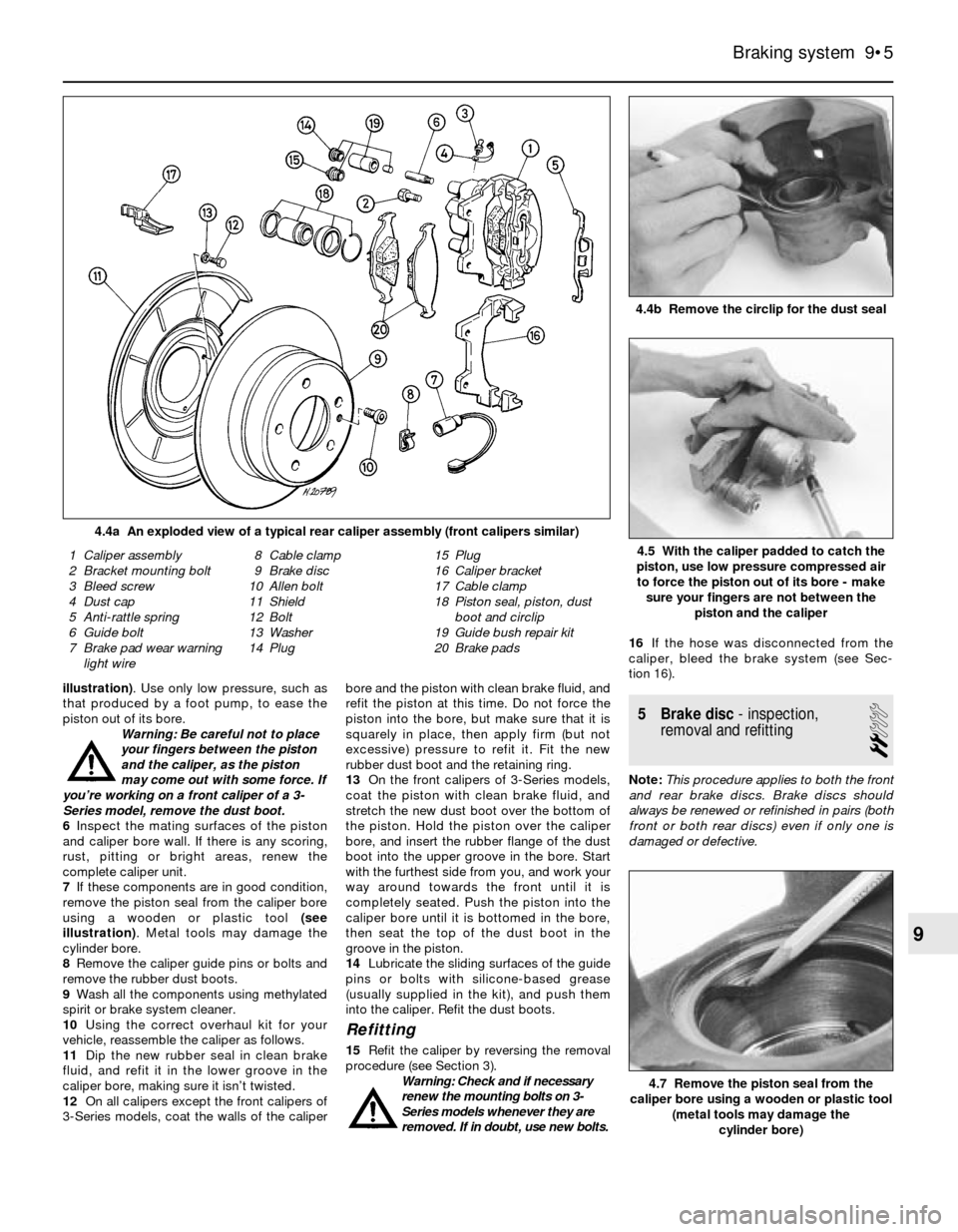
illustration). Use only low pressure, such as
that produced by a foot pump, to ease the
piston out of its bore.
Warning: Be careful not to place
your fingers between the piston
and the caliper, as the piston
may come out with some force. If
you’re working on a front caliper of a 3-
Series model, remove the dust boot.
6Inspect the mating surfaces of the piston
and caliper bore wall. If there is any scoring,
rust, pitting or bright areas, renew the
complete caliper unit.
7If these components are in good condition,
remove the piston seal from the caliper bore
using a wooden or plastic tool (see
illustration). Metal tools may damage the
cylinder bore.
8Remove the caliper guide pins or bolts and
remove the rubber dust boots.
9Wash all the components using methylated
spirit or brake system cleaner.
10Using the correct overhaul kit for your
vehicle, reassemble the caliper as follows.
11Dip the new rubber seal in clean brake
fluid, and refit it in the lower groove in the
caliper bore, making sure it isn’t twisted.
12On all calipers except the front calipers of
3-Series models, coat the walls of the caliperbore and the piston with clean brake fluid, and
refit the piston at this time. Do not force the
piston into the bore, but make sure that it is
squarely in place, then apply firm (but not
excessive) pressure to refit it. Fit the new
rubber dust boot and the retaining ring.
13On the front calipers of 3-Series models,
coat the piston with clean brake fluid, and
stretch the new dust boot over the bottom of
the piston. Hold the piston over the caliper
bore, and insert the rubber flange of the dust
boot into the upper groove in the bore. Start
with the furthest side from you, and work your
way around towards the front until it is
completely seated. Push the piston into the
caliper bore until it is bottomed in the bore,
then seat the top of the dust boot in the
groove in the piston.
14Lubricate the sliding surfaces of the guide
pins or bolts with silicone-based grease
(usually supplied in the kit), and push them
into the caliper. Refit the dust boots.
Refitting
15Refit the caliper by reversing the removal
procedure (see Section 3).
Warning: Check and if necessary
renew the mounting bolts on 3-
Series models whenever they are
removed. If in doubt, use new bolts.16If the hose was disconnected from the
caliper, bleed the brake system (see Sec-
tion 16).
5 Brake disc- inspection,
removal and refitting
2
Note:This procedure applies to both the front
and rear brake discs. Brake discs should
always be renewed or refinished in pairs (both
front or both rear discs) even if only one is
damaged or defective.
Braking system 9•5
4.4b Remove the circlip for the dust seal
4.4a An exploded view of a typical rear caliper assembly (front calipers similar)
4.7 Remove the piston seal from the
caliper bore using a wooden or plastic tool
(metal tools may damage the
cylinder bore)
1 Caliper assembly
2 Bracket mounting bolt
3 Bleed screw
4 Dust cap
5 Anti-rattle spring
6 Guide bolt
7 Brake pad wear warning
light wire8 Cable clamp
9 Brake disc
10 Allen bolt
11 Shield
12 Bolt
13 Washer
14 Plug15 Plug
16 Caliper bracket
17 Cable clamp
18 Piston seal, piston, dust
boot and circlip
19 Guide bush repair kit
20 Brake pads4.5 With the caliper padded to catch the
piston, use low pressure compressed air
to force the piston out of its bore - make
sure your fingers are not between the
piston and the caliper
9
Page 134 of 228
Inspection
1Loosen the wheel bolts, raise the vehicle
and support it securely on axle stands.
Remove the wheel, and refit three bolts to
hold the disc in place. If the rear brake disc is
being worked on, release the handbrake.
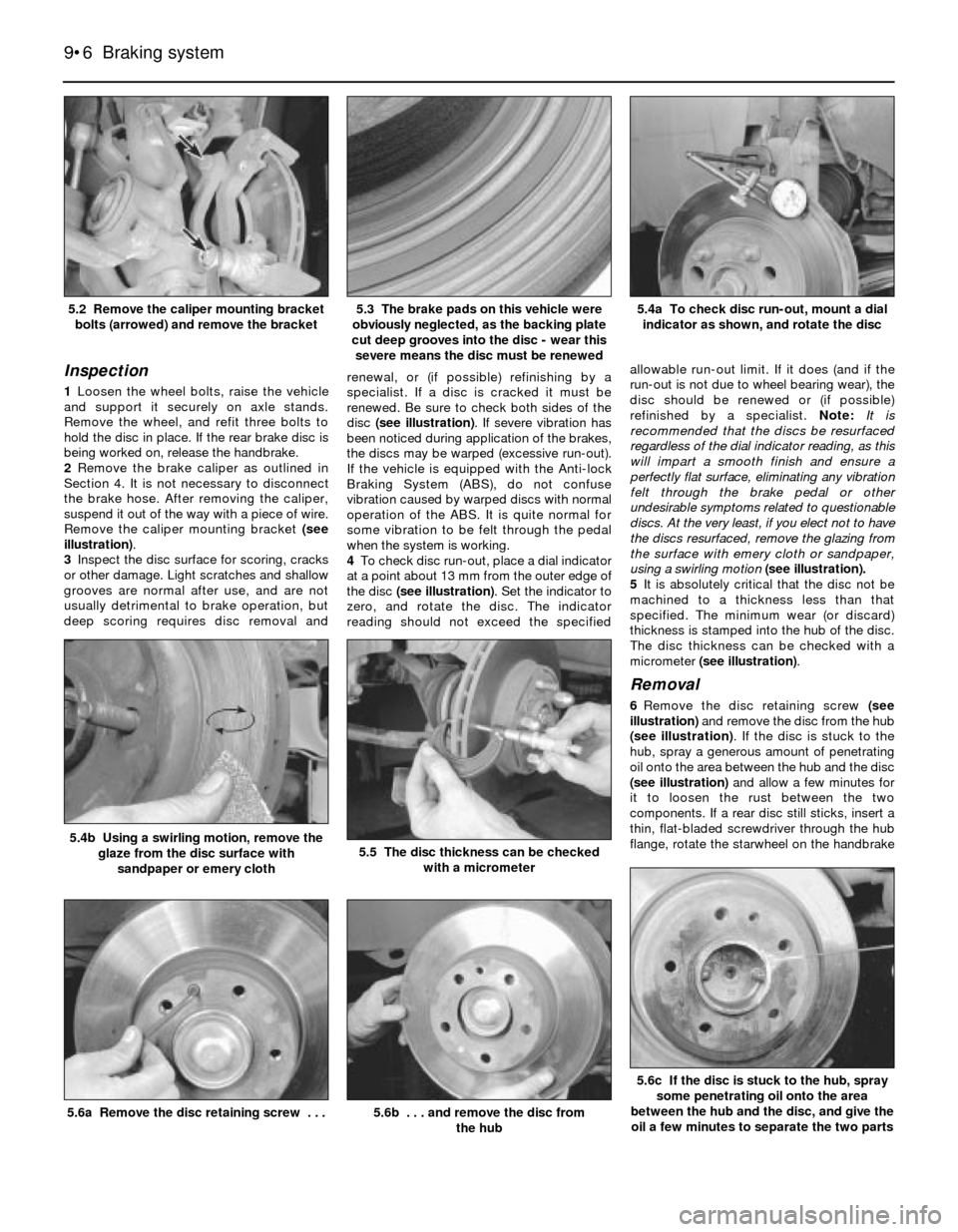
2Remove the brake caliper as outlined in
Section 4. It is not necessary to disconnect
the brake hose. After removing the caliper,
suspend it out of the way with a piece of wire.
Remove the caliper mounting bracket (see
illustration).
3Inspect the disc surface for scoring, cracks
or other damage. Light scratches and shallow
grooves are normal after use, and are not
usually detrimental to brake operation, but
deep scoring requires disc removal andrenewal, or (if possible) refinishing by a
specialist. If a disc is cracked it must be
renewed. Be sure to check both sides of the
disc (see illustration). If severe vibration has
been noticed during application of the brakes,
the discs may be warped (excessive run-out).
If the vehicle is equipped with the Anti-lock
Braking System (ABS), do not confuse
vibration caused by warped discs with normal
operation of the ABS. It is quite normal for
some vibration to be felt through the pedal
when the system is working.
4To check disc run-out, place a dial indicator
at a point about 13 mm from the outer edge of
the disc (see illustration). Set the indicator to
zero, and rotate the disc. The indicator
reading should not exceed the specifiedallowable run-out limit. If it does (and if the
run-out is not due to wheel bearing wear), the
disc should be renewed or (if possible)
refinished by a specialist. Note:It is
recommended that the discs be resurfaced
regardless of the dial indicator reading, as this
will impart a smooth finish and ensure a
perfectly flat surface, eliminating any vibration
felt through the brake pedal or other
undesirable symptoms related to questionable
discs. At the very least, if you elect not to have
the discs resurfaced, remove the glazing from
the surface with emery cloth or sandpaper,
using a swirling motion (see illustration).
5It is absolutely critical that the disc not be
machined to a thickness less than that
specified. The minimum wear (or discard)
thickness is stamped into the hub of the disc.
The disc thickness can be checked with a
micrometer (see illustration).
Removal
6Remove the disc retaining screw (see
illustration) and remove the disc from the hub
(see illustration). If the disc is stuck to the
hub, spray a generous amount of penetrating
oil onto the area between the hub and the disc
(see illustration)and allow a few minutes for
it to loosen the rust between the two
components. If a rear disc still sticks, insert a
thin, flat-bladed screwdriver through the hub
flange, rotate the starwheel on the handbrake
9•6 Braking system
5.6c If the disc is stuck to the hub, spray
some penetrating oil onto the area
between the hub and the disc, and give the
oil a few minutes to separate the two parts
5.6b . . . and remove the disc from
the hub5.6a Remove the disc retaining screw . . .
5.5 The disc thickness can be checked
with a micrometer5.4b Using a swirling motion, remove the
glaze from the disc surface with
sandpaper or emery cloth
5.4a To check disc run-out, mount a dial
indicator as shown, and rotate the disc5.3 The brake pads on this vehicle were
obviously neglected, as the backing plate
cut deep grooves into the disc - wear this
severe means the disc must be renewed5.2 Remove the caliper mounting bracket
bolts (arrowed) and remove the bracket