bolt BMW 3 SERIES 1985 E30 Repair Manual
[x] Cancel search | Manufacturer: BMW, Model Year: 1985, Model line: 3 SERIES, Model: BMW 3 SERIES 1985 E30Pages: 228, PDF Size: 7.04 MB
Page 99 of 228
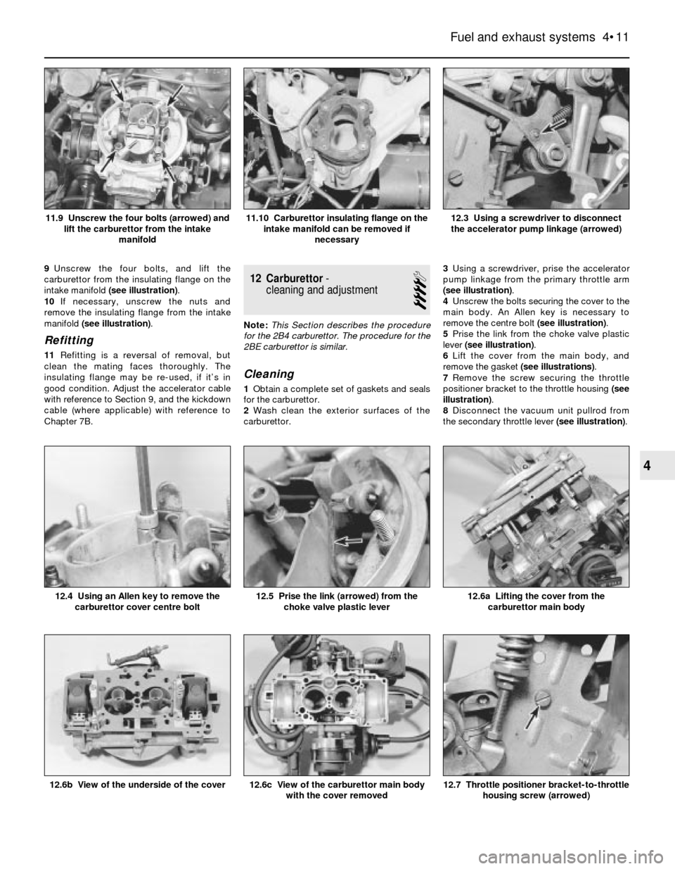
9Unscrew the four bolts, and lift the
carburettor from the insulating flange on the
intake manifold (see illustration).
10If necessary, unscrew the nuts and
remove the insulating flange from the intake
manifold (see illustration).
Refitting
11Refitting is a reversal of removal, but
clean the mating faces thoroughly. The
insulating flange may be re-used, if it’s in
good condition. Adjust the accelerator cable
with reference to Section 9, and the kickdown
cable (where applicable) with reference to
Chapter 7B.
12 Carburettor-
cleaning and adjustment
4
Note:This Section describes the procedure
for the 2B4 carburettor. The procedure for the
2BE carburettor is similar.
Cleaning
1Obtain a complete set of gaskets and seals
for the carburettor.
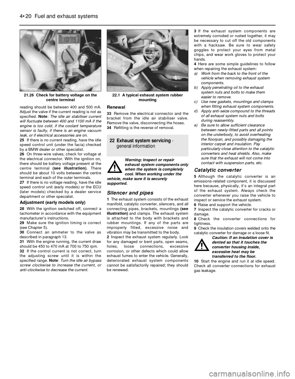
2Wash clean the exterior surfaces of the
carburettor.3Using a screwdriver, prise the accelerator
pump linkage from the primary throttle arm
(see illustration).
4Unscrew the bolts securing the cover to the
main body. An Allen key is necessary to
remove the centre bolt (see illustration).
5Prise the link from the choke valve plastic
lever (see illustration).
6Lift the cover from the main body, and
remove the gasket (see illustrations).
7Remove the screw securing the throttle
positioner bracket to the throttle housing (see
illustration).
8Disconnect the vacuum unit pullrod from
the secondary throttle lever (see illustration).
Fuel and exhaust systems 4•11
12.3 Using a screwdriver to disconnect
the accelerator pump linkage (arrowed)11.10 Carburettor insulating flange on the
intake manifold can be removed if
necessary11.9 Unscrew the four bolts (arrowed) and
lift the carburettor from the intake
manifold
12.7 Throttle positioner bracket-to-throttle
housing screw (arrowed)12.6c View of the carburettor main body
with the cover removed12.6b View of the underside of the cover
12.6a Lifting the cover from the
carburettor main body12.5 Prise the link (arrowed) from the
choke valve plastic lever12.4 Using an Allen key to remove the
carburettor cover centre bolt
4
Page 104 of 228
17 Throttle body- check,
removal and refitting
2
Check
1Detach the air intake duct from the throttle
body (see Section 8) and move the duct out of
the way.
2Have an assistant depress the throttle
pedal while you watch the throttle valve.
Check that the throttle valve moves smoothly
when the throttle is moved from closed (idle
position) to fully-open (wide-open throttle).
3If the throttle valve is not working properly,
renew the throttle body unit.
Warning: Wait until the engine is
completely cool before beginning
this procedure.
Caution: If the radio in your
vehicle is equipped with an anti-
theft system, make sure you
have the correct activation code
before disconnecting the battery. Refer to
the information on page 0-7 at the front of
this manual before detaching the cable.
Note: If, after connecting the battery, the
wrong language appears on the instrument
panel display, refer to page 0-7 for the
language resetting procedure.
Removal and refitting
4Detach the battery negative cable.
5Detach the air intake duct from the throttle
body, and place to one side.
6Detach the accelerator cable from the
throttle body (see Section 9).
7Detach the cruise control cable, if applicable.
8Clearly label all electrical connectors
(throttle position sensor, cold start injector,
idle air stabiliser, etc), then unplug them.
9Clearly label all vacuum hoses, then detach
them.
10Unscrew the radiator or expansion tank
cap to relieve any residual pressure in the
cooling system, then refit it. Clamp shut the
coolant hoses, then loosen the hose clamps
and detach the hoses. Be prepared for some
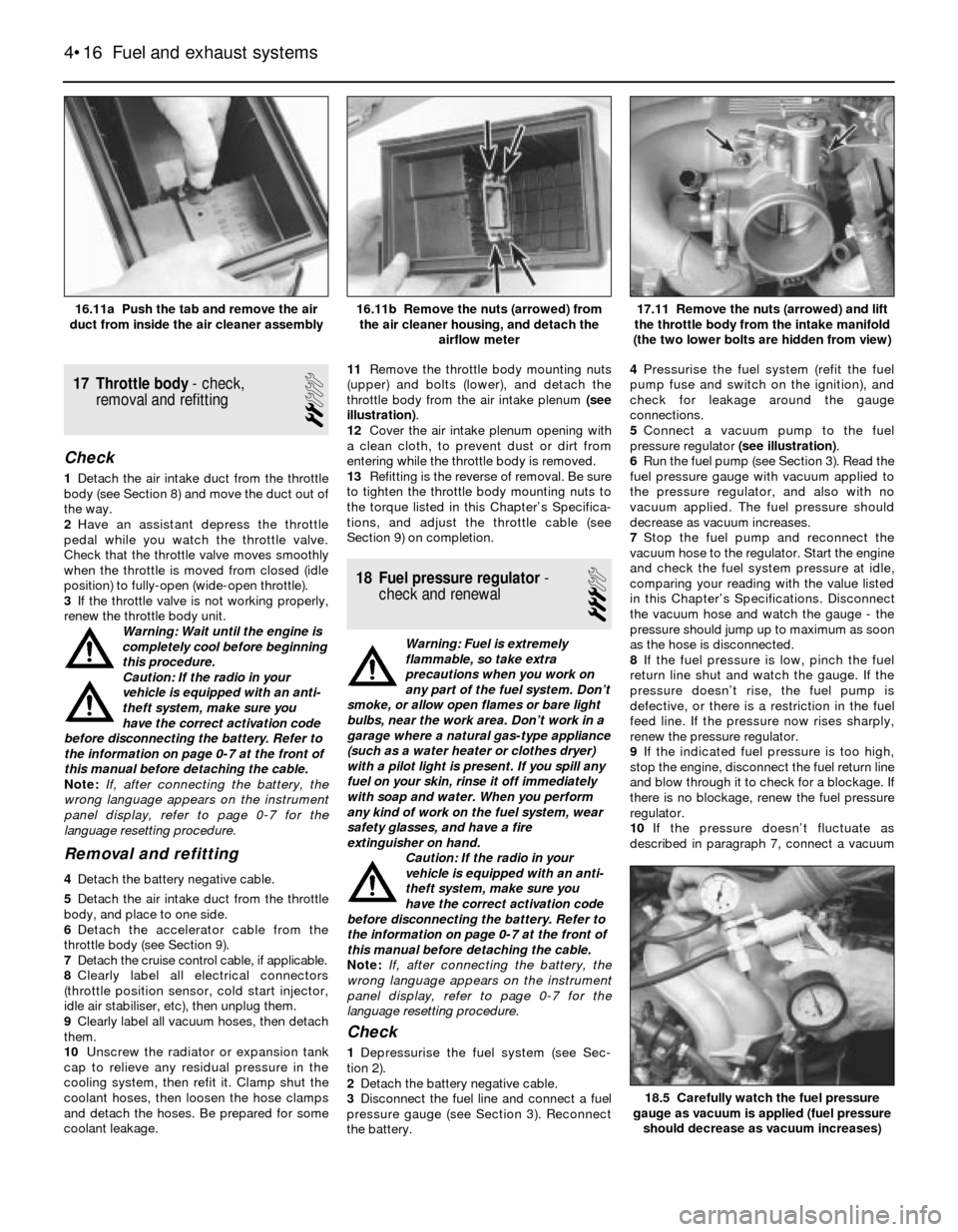
coolant leakage.11Remove the throttle body mounting nuts
(upper) and bolts (lower), and detach the
throttle body from the air intake plenum (see
illustration).
12Cover the air intake plenum opening with
a clean cloth, to prevent dust or dirt from
entering while the throttle body is removed.
13Refitting is the reverse of removal. Be sure
to tighten the throttle body mounting nuts to
the torque listed in this Chapter’s Specifica-
tions, and adjust the throttle cable (see
Section 9) on completion.
18 Fuel pressure regulator-
check and renewal
3
Warning: Fuel is extremely
flammable, so take extra
precautions when you work on
any part of the fuel system. Don’t
smoke, or allow open flames or bare light
bulbs, near the work area. Don’t work in a
garage where a natural gas-type appliance
(such as a water heater or clothes dryer)
with a pilot light is present. If you spill any
fuel on your skin, rinse it off immediately
with soap and water. When you perform
any kind of work on the fuel system, wear
safety glasses, and have a fire
extinguisher on hand.
Caution: If the radio in your
vehicle is equipped with an anti-
theft system, make sure you
have the correct activation code
before disconnecting the battery. Refer to
the information on page 0-7 at the front of
this manual before detaching the cable.
Note: If, after connecting the battery, the
wrong language appears on the instrument
panel display, refer to page 0-7 for the
language resetting procedure.
Check
1Depressurise the fuel system (see Sec-
tion 2).
2Detach the battery negative cable.
3Disconnect the fuel line and connect a fuel
pressure gauge (see Section 3). Reconnect
the battery.4Pressurise the fuel system (refit the fuel
pump fuse and switch on the ignition), and
check for leakage around the gauge
connections.
5Connect a vacuum pump to the fuel
pressure regulator (see illustration).
6Run the fuel pump (see Section 3). Read the
fuel pressure gauge with vacuum applied to
the pressure regulator, and also with no
vacuum applied. The fuel pressure should
decrease as vacuum increases.
7Stop the fuel pump and reconnect the
vacuum hose to the regulator. Start the engine
and check the fuel system pressure at idle,
comparing your reading with the value listed
in this Chapter’s Specifications. Disconnect
the vacuum hose and watch the gauge - the
pressure should jump up to maximum as soon
as the hose is disconnected.
8If the fuel pressure is low, pinch the fuel
return line shut and watch the gauge. If the
pressure doesn’t rise, the fuel pump is
defective, or there is a restriction in the fuel
feed line. If the pressure now rises sharply,
renew the pressure regulator.
9If the indicated fuel pressure is too high,
stop the engine, disconnect the fuel return line
and blow through it to check for a blockage. If
there is no blockage, renew the fuel pressure
regulator.
10If the pressure doesn’t fluctuate as
described in paragraph 7, connect a vacuum
4•16 Fuel and exhaust systems
18.5 Carefully watch the fuel pressure
gauge as vacuum is applied (fuel pressure
should decrease as vacuum increases)
17.11 Remove the nuts (arrowed) and lift
the throttle body from the intake manifold
(the two lower bolts are hidden from view)16.11b Remove the nuts (arrowed) from
the air cleaner housing, and detach the
airflow meter16.11a Push the tab and remove the air
duct from inside the air cleaner assembly
Page 105 of 228
gauge to the pressure regulator vacuum hose,
and check for vacuum (engine idling).
11If there is vacuum present, renew the fuel
pressure regulator.
12If there isn’t any reading on the gauge,
check the hose and its port for a leak or a
restriction.
Renewal
13Depressurise the fuel system (see Sec-
tion 2).
14Detach the battery negative cable.
Caution: If the radio in your
vehicle is equipped with an anti-
theft system, make sure you
have the correct activation code
before disconnecting the battery. Refer to
the information on page 0-7 at the front of
this manual before detaching the cable.
Note: If, after connecting the battery, the
wrong language appears on the instrument
panel display, refer to page 0-7 for the
language resetting procedure.
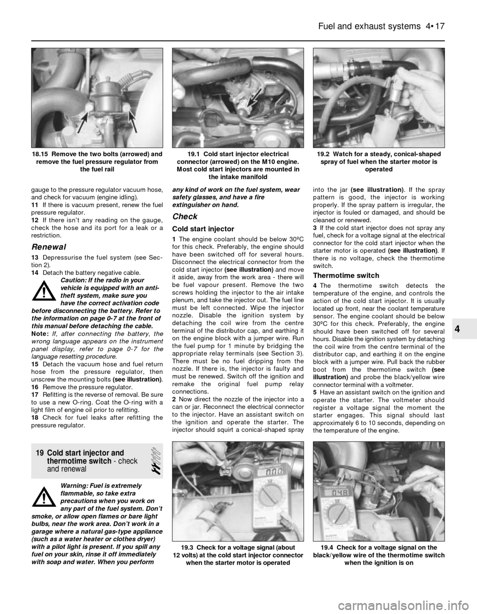
15Detach the vacuum hose and fuel return
hose from the pressure regulator, then
unscrew the mounting bolts (see illustration).
16Remove the pressure regulator.
17Refitting is the reverse of removal. Be sure
to use a new O-ring. Coat the O-ring with a
light film of engine oil prior to refitting.
18Check for fuel leaks after refitting the
pressure regulator.
19 Cold start injector and
thermotime switch- check
and renewal
2
Warning: Fuel is extremely
flammable, so take extra
precautions when you work on
any part of the fuel system. Don’t
smoke, or allow open flames or bare light
bulbs, near the work area. Don’t work in a
garage where a natural gas-type appliance
(such as a water heater or clothes dryer)
with a pilot light is present. If you spill any
fuel on your skin, rinse it off immediately
with soap and water. When you performany kind of work on the fuel system, wear
safety glasses, and have a fire
extinguisher on hand.
Check
Cold start injector
1The engine coolant should be below 30ºC
for this check. Preferably, the engine should
have been switched off for several hours.
Disconnect the electrical connector from the
cold start injector (see illustration)and move
it aside, away from the work area - there will
be fuel vapour present. Remove the two
screws holding the injector to the air intake
plenum, and take the injector out. The fuel line
must be left connected. Wipe the injector
nozzle. Disable the ignition system by
detaching the coil wire from the centre
terminal of the distributor cap, and earthing it
on the engine block with a jumper wire. Run
the fuel pump for 1 minute by bridging the
appropriate relay terminals (see Section 3).
There must be no fuel dripping from the
nozzle. If there is, the injector is faulty and
must be renewed. Switch off the ignition and
remake the original fuel pump relay
connections.
2Now direct the nozzle of the injector into a
can or jar. Reconnect the electrical connector
to the injector. Have an assistant switch on
the ignition and operate the starter. The
injector should squirt a conical-shaped sprayinto the jar (see illustration). If the spray
pattern is good, the injector is working
properly. If the spray pattern is irregular, the
injector is fouled or damaged, and should be
cleaned or renewed.
3If the cold start injector does not spray any
fuel, check for a voltage signal at the electrical
connector for the cold start injector when the
starter motor is operated (see illustration). If
there is no voltage, check the thermotime
switch.
Thermotime switch
4The thermotime switch detects the
temperature of the engine, and controls the
action of the cold start injector. It is usually
located up front, near the coolant temperature
sensor. The engine coolant should be below
30ºC for this check. Preferably, the engine
should have been switched off for several
hours. Disable the ignition system by detaching
the coil wire from the centre terminal of the
distributor cap, and earthing it on the engine
block with a jumper wire. Pull back the rubber
boot from the thermotime switch (see
illustration)and probe the black/yellow wire
connector terminal with a voltmeter.
5Have an assistant switch on the ignition and
operate the starter. The voltmeter should
register a voltage signal the moment the
starter engages. This signal should last
approximately 6 to 10 seconds, depending on
the temperature of the engine.
Fuel and exhaust systems 4•17
19.2 Watch for a steady, conical-shaped
spray of fuel when the starter motor is
operated19.1 Cold start injector electrical
connector (arrowed) on the M10 engine.
Most cold start injectors are mounted in
the intake manifold18.15 Remove the two bolts (arrowed) and
remove the fuel pressure regulator from
the fuel rail
19.4 Check for a voltage signal on the
black/yellow wire of the thermotime switch
when the ignition is on19.3 Check for a voltage signal (about
12 volts) at the cold start injector connector
when the starter motor is operated
4
Page 106 of 228
6If the voltage is correct, unplug the
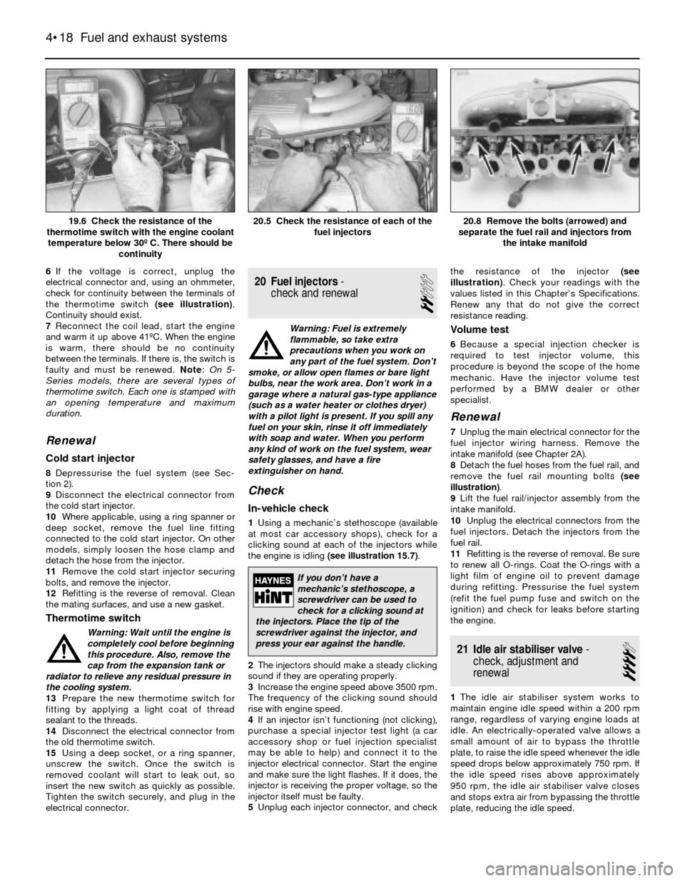
electrical connector and, using an ohmmeter,
check for continuity between the terminals of
the thermotime switch (see illustration).
Continuity should exist.
7Reconnect the coil lead, start the engine
and warm it up above 41ºC. When the engine
is warm, there should be no continuity
between the terminals. If there is, the switch is
faulty and must be renewed. Note: On 5-
Series models, there are several types of
thermotime switch. Each one is stamped with
an opening temperature and maximum
duration.
Renewal
Cold start injector
8Depressurise the fuel system (see Sec-
tion 2).
9Disconnect the electrical connector from
the cold start injector.
10Where applicable, using a ring spanner or
deep socket, remove the fuel line fitting
connected to the cold start injector. On other
models, simply loosen the hose clamp and
detach the hose from the injector.
11Remove the cold start injector securing
bolts, and remove the injector.
12Refitting is the reverse of removal. Clean
the mating surfaces, and use a new gasket.
Thermotime switch
Warning: Wait until the engine is
completely cool before beginning
this procedure. Also, remove the
cap from the expansion tank or
radiator to relieve any residual pressure in
the cooling system.
13Prepare the new thermotime switch for
fitting by applying a light coat of thread
sealant to the threads.
14Disconnect the electrical connector from
the old thermotime switch.
15Using a deep socket, or a ring spanner,
unscrew the switch. Once the switch is
removed coolant will start to leak out, so
insert the new switch as quickly as possible.
Tighten the switch securely, and plug in the
electrical connector.
20 Fuel injectors-
check and renewal
2
Warning: Fuel is extremely
flammable, so take extra
precautions when you work on
any part of the fuel system. Don’t
smoke, or allow open flames or bare light
bulbs, near the work area. Don’t work in a
garage where a natural gas-type appliance
(such as a water heater or clothes dryer)
with a pilot light is present. If you spill any
fuel on your skin, rinse it off immediately
with soap and water. When you perform
any kind of work on the fuel system, wear
safety glasses, and have a fire
extinguisher on hand.
Check
In-vehicle check
1Using a mechanic’s stethoscope (available
at most car accessory shops), check for a
clicking sound at each of the injectors while
the engine is idling (see illustration 15.7).
2The injectors should make a steady clicking
sound if they are operating properly.
3Increase the engine speed above 3500 rpm.
The frequency of the clicking sound should
rise with engine speed.
4If an injector isn’t functioning (not clicking),
purchase a special injector test light (a car
accessory shop or fuel injection specialist
may be able to help) and connect it to the
injector electrical connector. Start the engine
and make sure the light flashes. If it does, the
injector is receiving the proper voltage, so the
injector itself must be faulty.
5Unplug each injector connector, and checkthe resistance of the injector (see
illustration). Check your readings with the
values listed in this Chapter’s Specifications.
Renew any that do not give the correct
resistance reading.
Volume test
6Because a special injection checker is
required to test injector volume, this
procedure is beyond the scope of the home
mechanic. Have the injector volume test
performed by a BMW dealer or other
specialist.
Renewal
7Unplug the main electrical connector for the
fuel injector wiring harness. Remove the
intake manifold (see Chapter 2A).
8Detach the fuel hoses from the fuel rail, and
remove the fuel rail mounting bolts (see
illustration).
9Lift the fuel rail/injector assembly from the
intake manifold.
10Unplug the electrical connectors from the
fuel injectors. Detach the injectors from the
fuel rail.
11Refitting is the reverse of removal. Be sure
to renew all O-rings. Coat the O-rings with a
light film of engine oil to prevent damage
during refitting. Pressurise the fuel system
(refit the fuel pump fuse and switch on the
ignition) and check for leaks before starting
the engine.
21 Idle air stabiliser valve-
check, adjustment and
renewal
4
1The idle air stabiliser system works to
maintain engine idle speed within a 200 rpm
range, regardless of varying engine loads at
idle. An electrically-operated valve allows a
small amount of air to bypass the throttle
plate, to raise the idle speed whenever the idle
speed drops below approximately 750 rpm. If
the idle speed rises above approximately
950 rpm, the idle air stabiliser valve closes
and stops extra air from bypassing the throttle
plate, reducing the idle speed.
4•18 Fuel and exhaust systems
20.8 Remove the bolts (arrowed) and
separate the fuel rail and injectors from
the intake manifold20.5 Check the resistance of each of the
fuel injectors19.6 Check the resistance of the
thermotime switch with the engine coolant
temperature below 30º C. There should be
continuity
If you don’t have a
mechanic’s stethoscope, a
screwdriver can be used to
check for a clicking sound at
the injectors. Place the tip of the
screwdriver against the injector, and
press your ear against the handle.
Page 108 of 228
reading should be between 400 and 500 mA.
Adjust the valve if the current reading is not as
specified. Note: The idle air stabiliser current
will fluctuate between 400 and 1100 mA if the
engine is too cold, if the coolant temperature
sensor is faulty, if there is an engine vacuum
leak, or if electrical accessories are on.
25If there is no current reading, have the idle
speed control unit (under the facia) checked
by a BMW dealer or other specialist.
26On three-wire valves, check for voltage at
the electrical connector. With the ignition on,
there should be battery voltage present at the
centre terminal (see illustration). There
should be about 10 volts between the centre
terminal and each of the outer terminals.
27If there is no voltage reading, have the idle
speed control unit (early models) or the ECU
(later models) checked by a dealer service
department or other specialist.
Adjustment (early models only)
28With the ignition switched off, connect a
tachometer in accordance with the equipment
manufacturer’s instructions.
29Make sure the ignition timing is correct
(see Chapter 5).
30Connect an ammeter to the valve as
described in paragraph 13.
31With the engine running, the current draw
should be 450 to 470 mA at 700 to 750 rpm.
32If the control current is not correct, turn
the adjusting screw until it is within the
specified range. Note: Turn the idle air bypass
screw clockwise to increase the current, or
anti-clockwise to decrease the current.
Renewal
33Remove the electrical connector and the
bracket from the idle air stabiliser valve.
Remove the valve, disconnecting the hoses.
34Refitting is the reverse of removal.
22 Exhaust system servicing-
general information
Warning: Inspect or repair
exhaust system components only
when the system is completely
cool. When working under the
vehicle, make sure it is securely
supported.
Silencer and pipes
1The exhaust system consists of the exhaust
manifold, catalytic converter, silencers, and all
connecting pipes, brackets, mountings (see
illustration)and clamps. The exhaust system
is attached to the body with brackets and
rubber mountings. If any of the parts are
improperly fitted, excessive noise and
vibration may be transmitted to the body.
2Inspect the exhaust system regularly. Look
for any damaged or bent parts, open seams,
holes, loose connections, excessive
corrosion, or other defects which could allow
exhaust fumes to enter the vehicle. Generally,
deteriorated exhaust system components
cannot be satisfactorily repaired; they should
be renewed.3If the exhaust system components are
extremely corroded or rusted together, it may
be necessary to cut off the old components
with a hacksaw. Be sure to wear safety
goggles to protect your eyes from metal
chips, and wear work gloves to protect your
hands.
4Here are some simple guidelines to follow
when repairing the exhaust system:
a) Work from the back to the front of the
vehicle when removing exhaust system
components.
b) Apply penetrating oil to the exhaust
system nuts and bolts to make them
easier to remove.
c) Use new gaskets, mountings and clamps
when fitting exhaust system components.
d) Apply anti-seize compound to the threads
of all exhaust system nuts and bolts
during reassembly.
e) Be sure to allow sufficient clearance
between newly-fitted parts and all points
on the underbody, to avoid overheating
the floorpan, and possibly damaging the
interior carpet and insulation. Pay
particularly close attention to the catalytic
converters and heat shields. Also, make
sure that the exhaust will not come into
contact with suspension parts, etc.
Catalytic converter
5Although the catalytic converter is an
emissions-related component, it is discussed
here because, physically, it’s an integral part
of the exhaust system. Always check the
converter whenever you raise the vehicle to
inspect or service the exhaust system.
6Raise and support the vehicle.
7Inspect the catalytic converter for cracks or
damage.
8Check the converter connections for
tightness.
9Check the insulation covers welded onto the
catalytic converter for damage or a loose fit.
Caution: If an insulation cover is
dented so that it touches the
converter housing inside,
excessive heat may be
transferred to the floor.
10Start the engine and run it at idle speed.
Check all converter connections for exhaust
gas leakage.
4•20 Fuel and exhaust systems
22.1 A typical exhaust system rubber
mounting21.26 Check for battery voltage on the
centre terminal
Page 112 of 228
1 General information
The engine electrical systems include all
ignition, charging and starting components.
Because of their engine-related functions,
these components are discussed separately
from body-related electrical devices such as
the lights, the instruments, etc. (which are
included in Chapter 12).
Always observe the following precautions
when working on the electrical systems:
a) Be extremely careful when servicing
engine electrical components. They are
easily damaged if improperly checked,
connected or handled.
b) Never leave the ignition switched on for
long periods of time with the engine off.
c) Don’t disconnect the battery cables while
the engine is running.
d) Observe the rules when jump-starting
your vehicle. Read the precautions at the
front of this manual.
e) Always disconnect the battery negative
cable first, and connect it last, to reduce
the risk of accidental short-circuits.
f) Don’t charge the battery with the cables
connected to the terminals.
It’s also a good idea to review the safety-
related information regarding the engine
electrical systems in the “Safety first”section
near the front of this manual before beginning
any operation included in this Chapter.
Caution: If the radio in your
vehicle is equipped with an anti-
theft system, make sure you
have the correct activation code
before disconnecting the battery. Refer to
the information on page 0-7 at the front of
this manual before detaching the cable.
Note: If, after connecting the battery, the
wrong language appears on the instrument
panel display, refer to page 0-7 for the
language resetting procedure.
2 Battery-
emergency jump starting
1
Refer to the “Jump starting”procedure at
the front of this manual.
3 Battery- removal and refitting
1
Note:Depending on the model, the battery
may be located in the engine compartment, in
the rear luggage compartment, or under the
rear seat. Consult your owners handbook for
the location of the battery, if not already
known to you.Caution: If the radio in your
vehicle is equipped with an anti-
theft system, make sure you
have the correct activation code
before disconnecting the battery. Refer to
the information on page 0-7 at the front of
this manual before detaching the cable.
Note: If, after connecting the battery, the
wrong language appears on the instrument
panel display, refer to page 0-7 for the
language resetting procedure.
1Disconnect the battery negative cable.
2Detach the cable from the positive terminal.
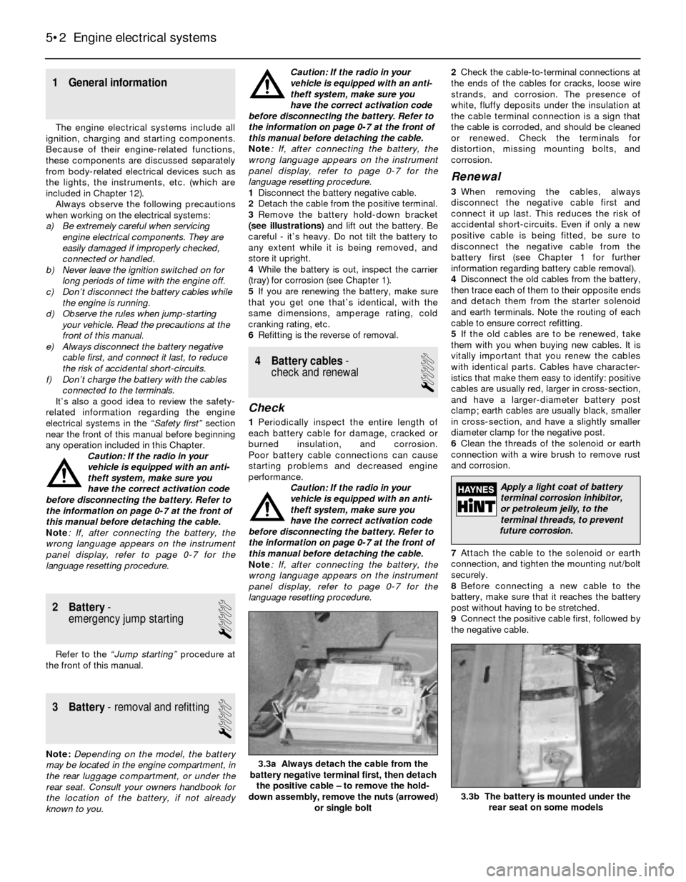
3Remove the battery hold-down bracket
(see illustrations)and lift out the battery. Be
careful - it’s heavy. Do not tilt the battery to
any extent while it is being removed, and
store it upright.
4While the battery is out, inspect the carrier
(tray) for corrosion (see Chapter 1).
5If you are renewing the battery, make sure
that you get one that’s identical, with the
same dimensions, amperage rating, cold
cranking rating, etc.
6Refitting is the reverse of removal.
4 Battery cables-
check and renewal
1
Check
1Periodically inspect the entire length of
each battery cable for damage, cracked or
burned insulation, and corrosion.
Poor battery cable connections can cause
starting problems and decreased engine
performance.
Caution: If the radio in your
vehicle is equipped with an anti-
theft system, make sure you
have the correct activation code
before disconnecting the battery. Refer to
the information on page 0-7 at the front of
this manual before detaching the cable.
Note: If, after connecting the battery, the
wrong language appears on the instrument
panel display, refer to page 0-7 for the
language resetting procedure.2Check the cable-to-terminal connections at
the ends of the cables for cracks, loose wire
strands, and corrosion. The presence of
white, fluffy deposits under the insulation at
the cable terminal connection is a sign that
the cable is corroded, and should be cleaned
or renewed. Check the terminals for
distortion, missing mounting bolts, and
corrosion.
Renewal
3When removing the cables, always
disconnect the negative cable first and
connect it up last. This reduces the risk of
accidental short-circuits. Even if only a new
positive cable is being fitted, be sure to
disconnect the negative cable from the
battery first (see Chapter 1 for further
information regarding battery cable removal).
4Disconnect the old cables from the battery,
then trace each of them to their opposite ends
and detach them from the starter solenoid
and earth terminals. Note the routing of each
cable to ensure correct refitting.
5If the old cables are to be renewed, take
them with you when buying new cables. It is
vitally important that you renew the cables
with identical parts. Cables have character-
istics that make them easy to identify: positive
cables are usually red, larger in cross-section,
and have a larger-diameter battery post
clamp; earth cables are usually black, smaller
in cross-section, and have a slightly smaller
diameter clamp for the negative post.
6Clean the threads of the solenoid or earth
connection with a wire brush to remove rust
and corrosion.
7Attach the cable to the solenoid or earth
connection, and tighten the mounting nut/bolt
securely.
8Before connecting a new cable to the
battery, make sure that it reaches the battery
post without having to be stretched.
9Connect the positive cable first, followed by
the negative cable.
5•2 Engine electrical systems
3.3b The battery is mounted under the
rear seat on some models
3.3a Always detach the cable from the
battery negative terminal first, then detach
the positive cable – to remove the hold-
down assembly, remove the nuts (arrowed)
or single bolt
Apply a light coat of battery
terminal corrosion inhibitor,
or petroleum jelly, to the
terminal threads, to prevent
future corrosion.
Page 113 of 228
5 Ignition system- general
information and precautions
The ignition system includes the ignition
switch, the battery, the distributor, the primary
(low-voltage/low-tension or LT) and
secondary (high-voltage/high-tension or HT)
wiring circuits, the spark plugs and the spark
plug leads. Models fitted with a carburettor or
L-Jetronic fuel injection are equipped with a
Transistorised Coil Ignition (TCI) system.
Models fitted with the Motronic fuel injection
system have the ignition system incorporated
within the Motronic system (Digital Motor
Electronics or DME).
Transistorised Coil Ignition (TCI)
system
This system is has four major components;
the impulse generator, the ignition control
unit, the coil, and the spark plugs. The
impulse generator provides a timing signal for
the ignition system. Equivalent to cam-
actuated breaker points in a standard
distributor, the impulse generator creates an
A/C voltage signal every time the trigger
wheel tabs pass the impulse generator tabs.
When the ignition control unit (capacitive
discharge unit) receives the voltage signal, it
triggers a spark discharge from the coil by
interrupting the primary coil circuit. The
ignition dwell (coil charging time) is adjusted
by the ignition control unit for the most
intense spark. Note: The air gap (distance
between the impulse generator and trigger
wheel tabs) can be adjusted (see Section 11).
Ignition timing is mechanically adjusted
(see Section 7). A centrifugal advance unit
that consists of spring-loaded rotating
weights advances ignition timing as engine
speed increases. The vacuum advance
adjusts ignition timing to compensate for
changes in engine load.
Motronic ignition system
This system, also known as Digital Motor
Electronics (DME), incorporates all ignition
and fuel injection functions into one central
control unit or ECU (computer). The ignition
timing is based on inputs the ECU receives for
engine load, engine speed, coolant
temperature and intake air temperature. The
only function the distributor performs is the
distribution of the high voltage signal to the
individual spark plugs. The distributor is
attached directly to the cylinder head. There is
no mechanical spark advance system used on
these systems.
Ignition timing is electronically-controlled,
and is not adjustable on Motronic systems.
During starting, a crankshaft position sensor
(reference sensor) relays the crankshaft
position to the ECU, and an initial baseline
ignition point is determined. Once the engineis running, the ignition timing is continually
changing, based on the various input signals
to the ECU. Engine speed is signalled by a
speed sensor. Early Motronic systems have
the position reference sensor and the speed
sensor mounted on the bellhousing over the
flywheel on the left-hand side. Later Motronic
systems have a single sensor (pulse sensor)
mounted over the crankshaft pulley. This
sensor functions as a speed sensor as well as
a position reference sensor. Refer to Sec-
tion 12 for checking and renewing the ignition
sensors. Note: Some models are equipped
with a TDC sensor mounted on the front of the
engine. This sensor is strictly for the BMW
service test unit, and it is not part of the
Motronic ignition system.
Precautions
Certain precautions must be observed
when working on a transistorised ignition
system.
a) Do not disconnect the battery cables
when the engine is running
b) Make sure the ignition control unit (TCI
ignition system) is always well earthed
(see Section 10).
c) Keep water away from the distributor and
HT leads.
d) If a tachometer is to be connected to the
engine, always connect the tachometer
positive (+) lead to the ignition coil
negative terminal (-) and never to the
distributor.
e) Do not allow the coil terminals to be
earthed, as the impulse generator or coil
could be damaged.
f) Do not leave the ignition switch on for
more than ten minutes with the engine
off, or if the engine will not start.
6 Ignition system- check
2
Warning: Because of the high
voltage generated by the ignition
system, extreme care should be
taken whenever an operation is
performed involving ignition components.
This not only includes the impulse
generator (electronic ignition), coil,
distributor and spark plug HT leads, but
related components such as spark plug
connectors, tachometer and other test
equipment.
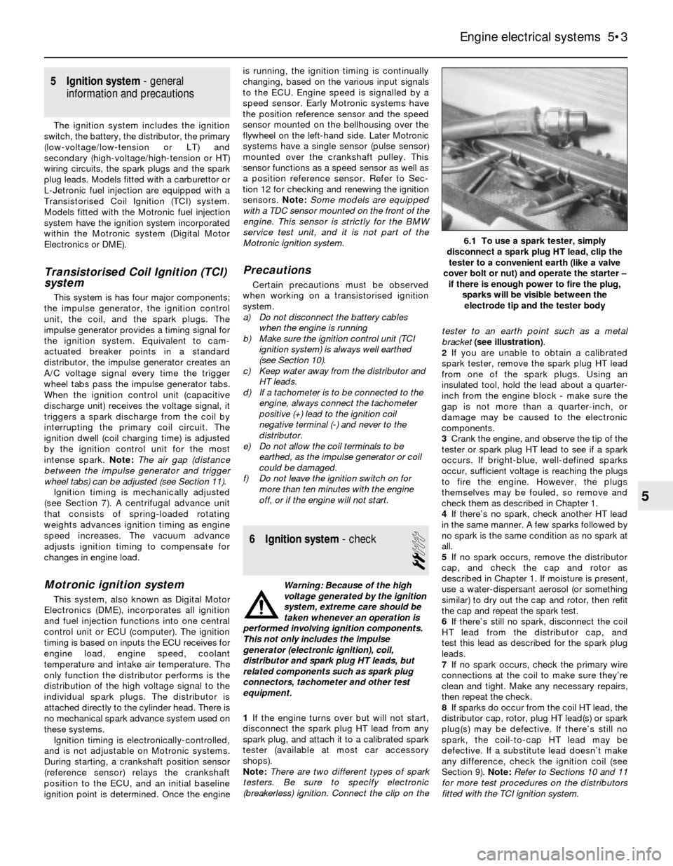
1If the engine turns over but will not start,
disconnect the spark plug HT lead from any
spark plug, and attach it to a calibrated spark
tester (available at most car accessory
shops).
Note:There are two different types of spark
testers. Be sure to specify electronic
(breakerless) ignition. Connect the clip on thetester to an earth point such as a metal
bracket (see illustration).
2If you are unable to obtain a calibrated
spark tester, remove the spark plug HT lead
from one of the spark plugs. Using an
insulated tool, hold the lead about a quarter-
inch from the engine block - make sure the
gap is not more than a quarter-inch, or
damage may be caused to the electronic
components.
3Crank the engine, and observe the tip of the
tester or spark plug HT lead to see if a spark
occurs. If bright-blue, well-defined sparks
occur, sufficient voltage is reaching the plugs
to fire the engine. However, the plugs
themselves may be fouled, so remove and
check them as described in Chapter 1.
4If there’s no spark, check another HT lead
in the same manner. A few sparks followed by
no spark is the same condition as no spark at
all.
5If no spark occurs, remove the distributor
cap, and check the cap and rotor as
described in Chapter 1. If moisture is present,
use a water-dispersant aerosol (or something
similar) to dry out the cap and rotor, then refit
the cap and repeat the spark test.
6If there’s still no spark, disconnect the coil
HT lead from the distributor cap, and
test this lead as described for the spark plug
leads.
7If no spark occurs, check the primary wire
connections at the coil to make sure they’re
clean and tight. Make any necessary repairs,
then repeat the check.
8If sparks do occur from the coil HT lead, the
distributor cap, rotor, plug HT lead(s) or spark
plug(s) may be defective. If there’s still no
spark, the coil-to-cap HT lead may be
defective. If a substitute lead doesn’t make
any difference, check the ignition coil (see
Section 9). Note:Refer to Sections 10 and 11
for more test procedures on the distributors
fitted with the TCI ignition system.
Engine electrical systems 5•3
6.1 To use a spark tester, simply
disconnect a spark plug HT lead, clip the
tester to a convenient earth (like a valve
cover bolt or nut) and operate the starter –
if there is enough power to fire the plug,
sparks will be visible between the
electrode tip and the tester body
5
Page 114 of 228
7 Ignition timing (TCI system)-
check and adjustment
4
Warning: Keep hands, equipment
and wires well clear of the
viscous cooling fan during
adjustment of the ignition timing.
Note:This Section describes the procedure
for checking and adjusting the ignition timing
on engines fitted with the TCI system. On
engines fitted with the Motronic engine
management system, the ignition timing is
controlled by the electronic control unit, and
no adjustment is possible. The timing can be
checked using the following procedure, but no
ignition timing values were available at the
time of writing. If the timing is thought to be
incorrect, refer to a BMW dealer.
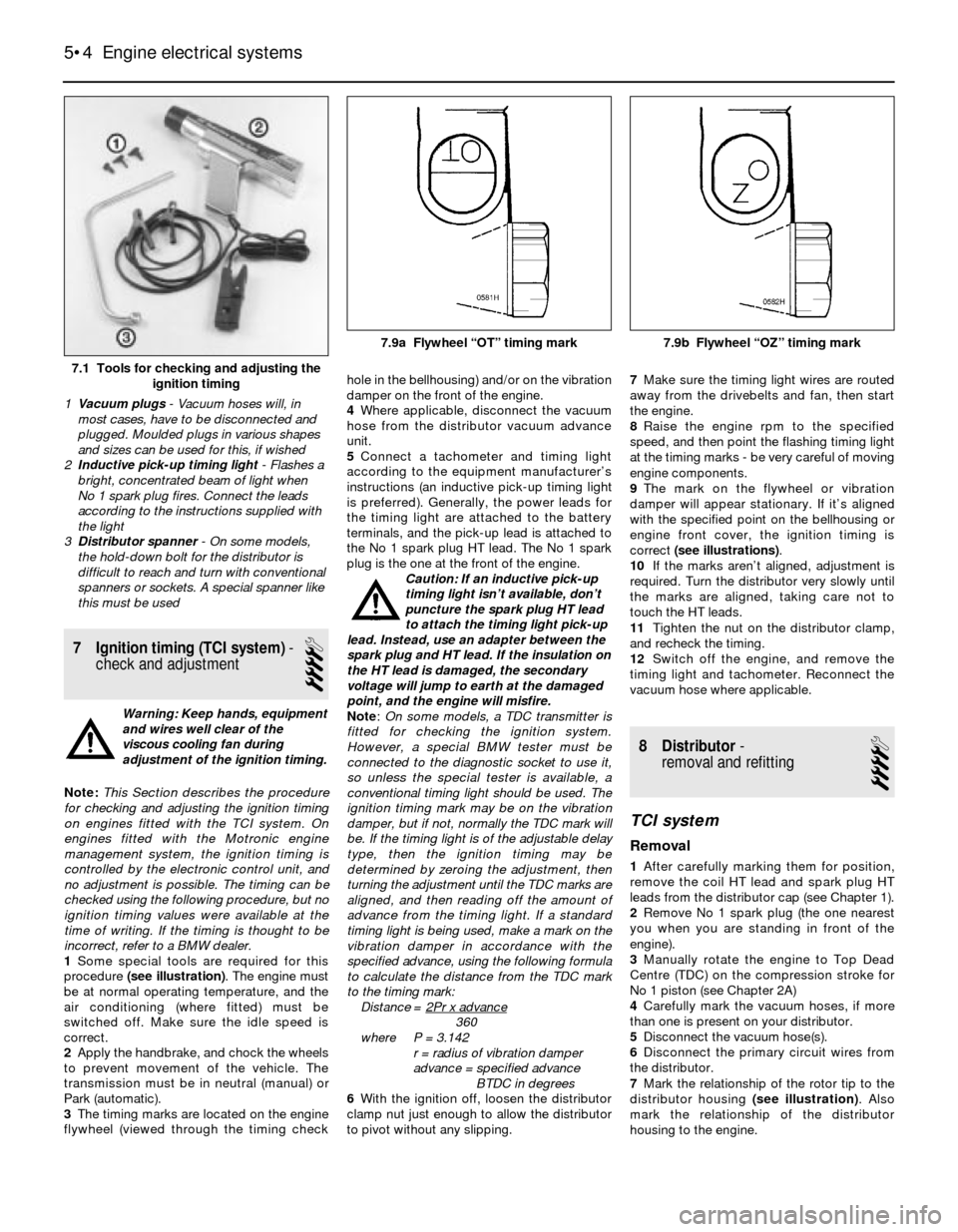
1Some special tools are required for this
procedure (see illustration). The engine must
be at normal operating temperature, and the
air conditioning (where fitted) must be
switched off. Make sure the idle speed is
correct.
2Apply the handbrake, and chock the wheels
to prevent movement of the vehicle. The
transmission must be in neutral (manual) or
Park (automatic).
3The timing marks are located on the engine
flywheel (viewed through the timing checkhole in the bellhousing) and/or on the vibration
damper on the front of the engine.
4Where applicable, disconnect the vacuum
hose from the distributor vacuum advance
unit.
5Connect a tachometer and timing light
according to the equipment manufacturer’s
instructions (an inductive pick-up timing light
is preferred). Generally, the power leads for
the timing light are attached to the battery
terminals, and the pick-up lead is attached to
the No 1 spark plug HT lead. The No 1 spark
plug is the one at the front of the engine.
Caution: If an inductive pick-up
timing light isn’t available, don’t
puncture the spark plug HT lead
to attach the timing light pick-up
lead. Instead, use an adapter between the
spark plug and HT lead. If the insulation on
the HT lead is damaged, the secondary
voltage will jump to earth at the damaged
point, and the engine will misfire.
Note:On some models, a TDC transmitter is
fitted for checking the ignition system.
However, a special BMW tester must be
connected to the diagnostic socket to use it,
so unless the special tester is available, a
conventional timing light should be used. The
ignition timing mark may be on the vibration
damper, but if not, normally the TDC mark will
be. If the timing light is of the adjustable delay
type, then the ignition timing may be
determined by zeroing the adjustment, then
turning the adjustment until the TDC marks are
aligned, and then reading off the amount of
advance from the timing light. If a standard
timing light is being used, make a mark on the
vibration damper in accordance with the
specified advance, using the following formula
to calculate the distance from the TDC mark
to the timing mark:
Distance = 2Pr x advance
360
where P = 3.142
r = radius of vibration damper
advance = specified advance
BTDC in degrees
6With the ignition off, loosen the distributor
clamp nut just enough to allow the distributor
to pivot without any slipping.7Make sure the timing light wires are routed
away from the drivebelts and fan, then start
the engine.
8Raise the engine rpm to the specified
speed, and then point the flashing timing light
at the timing marks - be very careful of moving
engine components.
9The mark on the flywheel or vibration
damper will appear stationary. If it’s aligned
with the specified point on the bellhousing or
engine front cover, the ignition timing is
correct (see illustrations).
10If the marks aren’t aligned, adjustment is
required. Turn the distributor very slowly until
the marks are aligned, taking care not to
touch the HT leads.
11Tighten the nut on the distributor clamp,
and recheck the timing.
12Switch off the engine, and remove the
timing light and tachometer. Reconnect the
vacuum hose where applicable.
8 Distributor-
removal and refitting
4
TCI system
Removal
1After carefully marking them for position,
remove the coil HT lead and spark plug HT
leads from the distributor cap (see Chapter 1).
2Remove No 1 spark plug (the one nearest
you when you are standing in front of the
engine).
3Manually rotate the engine to Top Dead
Centre (TDC) on the compression stroke for
No 1 piston (see Chapter 2A)
4Carefully mark the vacuum hoses, if more
than one is present on your distributor.
5Disconnect the vacuum hose(s).
6Disconnect the primary circuit wires from
the distributor.
7Mark the relationship of the rotor tip to the
distributor housing (see illustration). Also
mark the relationship of the distributor
housing to the engine.
5•4 Engine electrical systems
7.1 Tools for checking and adjusting the
ignition timing
1Vacuum plugs- Vacuum hoses will, in
most cases, have to be disconnected and
plugged. Moulded plugs in various shapes
and sizes can be used for this, if wished
2Inductive pick-up timing light- Flashes a
bright, concentrated beam of light when
No 1 spark plug fires. Connect the leads
according to the instructions supplied with
the light
3Distributor spanner - On some models,
the hold-down bolt for the distributor is
difficult to reach and turn with conventional
spanners or sockets. A special spanner like
this must be used
7.9a Flywheel “OT” timing mark 7.9b Flywheel “OZ” timing mark
Page 115 of 228
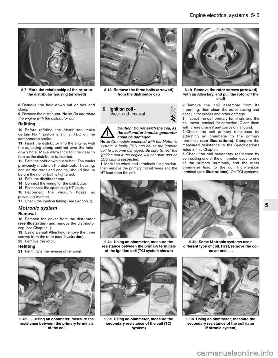
8Remove the hold-down nut or bolt and
clamp.
9Remove the distributor. Note:Do not rotate
the engine with the distributor out.
Refitting
10Before refitting the distributor, make
certain No 1 piston is still at TDC on the
compression stroke.
11Insert the distributor into the engine, with
the adjusting clamp centred over the hold-
down hole. Make allowance for the gear to
turn as the distributor is inserted.
12Refit the hold-down nut or bolt. The marks
previously made on the distributor housing,
and on the rotor and engine, should line up
before the nut or bolt is tightened.
13Refit the distributor cap.
14Connect the wiring for the distributor.
15Reconnect the spark plug HT leads.
16Reconnect the vacuum hoses as
previously marked.
17Check the ignition timing (see Section 7).
Motronic system
Removal
18Remove the cover from the distributor
(see illustration)and remove the distributor
cap (see Chapter 1).
19Using a small Allen key, remove the three
screws from the rotor (see illustration).
20Remove the rotor.
Refitting
21Refitting is the reverse of removal.
9 Ignition coil -
check and renewal
2
Caution: Do not earth the coil, as
the coil and/or impulse generator
could be damaged.
Note:On models equipped with the Motronic
system, a faulty ECU can cause the ignition
coil to become damaged. Be sure to test the
ignition coil if the engine will not start and an
ECU fault is suspected.
1Mark the wires and terminals for position,
then remove the primary circuit wires and the
HT lead from the coil.2Remove the coil assembly from its
mounting, then clean the outer casing and
check it for cracks and other damage.
3Inspect the coil primary terminals and the
coil tower terminal for corrosion. Clean them
with a wire brush if any corrosion is found.
4Check the coil primary resistance by
attaching an ohmmeter to the primary
terminals (see illustrations). Compare the
measured resistance to the Specifications
listed in this Chapter.
5Check the coil secondary resistance by
connecting one of the ohmmeter leads to one
of the primary terminals, and the other
ohmmeter lead to the coil high-tension
terminal (see illustrations). On TCI systems,
Engine electrical systems 5•5
8.19 Remove the rotor screws (arrowed)
with an Allen key, and pull the rotor off the
shaft8.18 Remove the three bolts (arrowed)
from the distributor cap8.7 Mark the relationship of the rotor to
the distributor housing (arrowed)
9.5b Using an ohmmeter, measure the
secondary resistance of the coil (later
Motronic system)9.5a Using an ohmmeter, measure the
secondary resistance of the coil (TCI
system)
9.4b Some Motronic systems use a
different type of coil. First, remove the coil
cover and . . .9.4a Using an ohmmeter, measure the
resistance between the primary terminals
of the ignition coil (TCI system shown)
9.4c . . . using an ohmmeter, measure the
resistance between the primary terminals
of the coil
5
Page 118 of 228
and down - you should feel a slight drag on
the feeler gauge as it is moved if the gap is
correct. The gap must be as given in this
Chapter’s Specifications.
3To adjust the gap, it is necessary to remove
the impulse generator and the baseplate
assembly from the distributor (see illus-
tration 10.1).
4Follow paragraphs 17 to 24 in Section 10
and loosen the screws that retain the impulse
generator to the baseplate assembly.
5Carefully insert the feeler gauge and tighten
the screws.
6Refit the assembly back into the distributor
and recheck the adjustment.12 Ignition sensors (Motronic
system)- check and renewal
2
Note:Some models are equipped with a TDC
sensor mounted on the front of the engine.
This sensor is strictly for the BMW service test
unit, and is not part of the Motronic ignition
system.
Speed and position sensors
Check
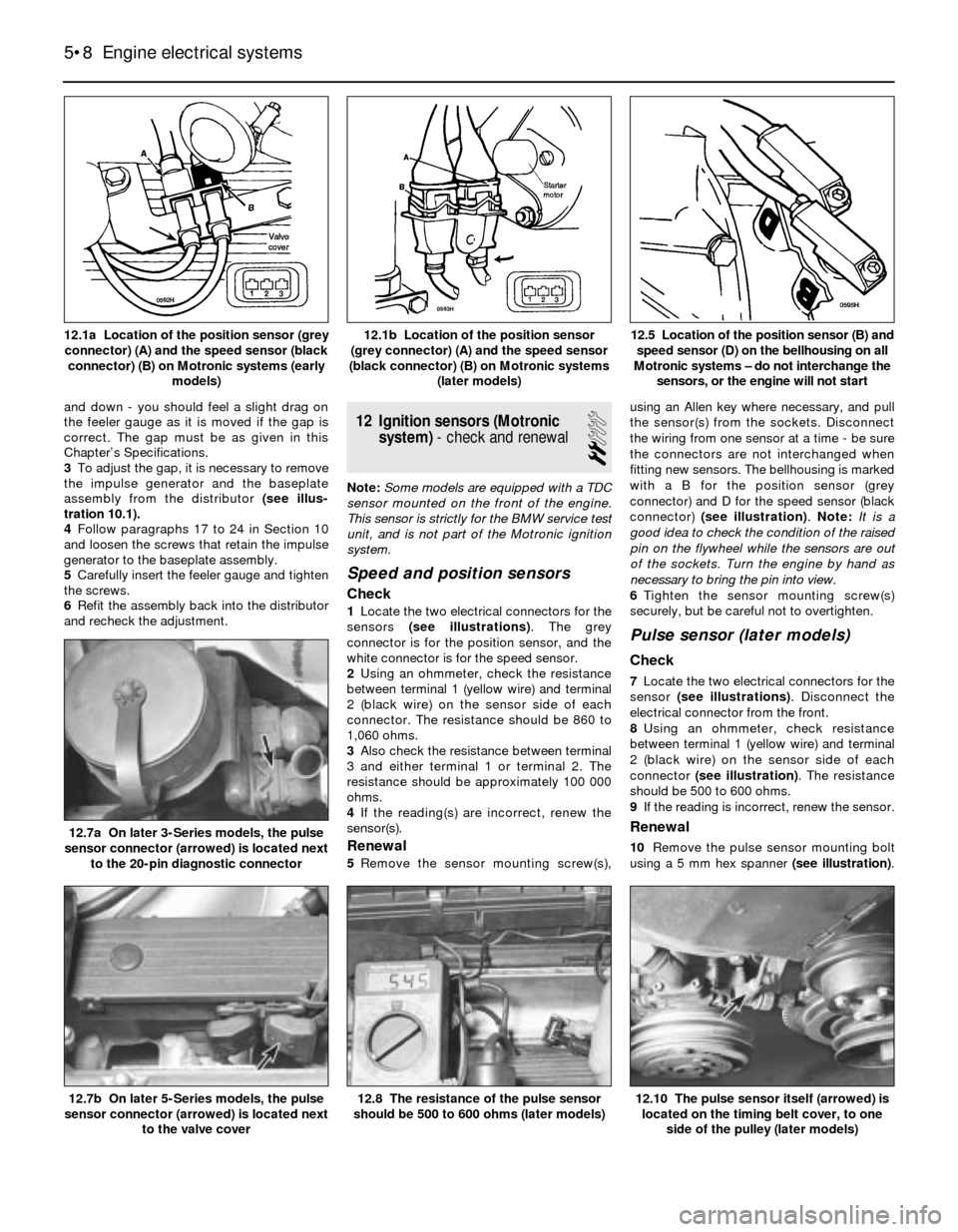
1Locate the two electrical connectors for the
sensors (see illustrations). The grey
connector is for the position sensor, and the
white connector is for the speed sensor.
2Using an ohmmeter, check the resistance
between terminal 1 (yellow wire) and terminal
2 (black wire) on the sensor side of each
connector. The resistance should be 860 to
1,060 ohms.
3Also check the resistance between terminal
3 and either terminal 1 or terminal 2. The
resistance should be approximately 100 000
ohms.
4If the reading(s) are incorrect, renew the
sensor(s).
Renewal
5Remove the sensor mounting screw(s),using an Allen key where necessary, and pull
the sensor(s) from the sockets. Disconnect
the wiring from one sensor at a time - be sure
the connectors are not interchanged when
fitting new sensors. The bellhousing is marked
with a B for the position sensor (grey
connector) and D for the speed sensor (black
connector) (see illustration). Note: It is a
good idea to check the condition of the raised
pin on the flywheel while the sensors are out
of the sockets. Turn the engine by hand as
necessary to bring the pin into view.
6Tighten the sensor mounting screw(s)
securely, but be careful not to overtighten.
Pulse sensor (later models)
Check
7Locate the two electrical connectors for the
sensor (see illustrations). Disconnect the
electrical connector from the front.
8Using an ohmmeter, check resistance
between terminal 1 (yellow wire) and terminal
2 (black wire) on the sensor side of each
connector (see illustration). The resistance
should be 500 to 600 ohms.
9If the reading is incorrect, renew the sensor.
Renewal
10Remove the pulse sensor mounting bolt
using a 5 mm hex spanner (see illustration).
5•8 Engine electrical systems
12.10 The pulse sensor itself (arrowed) is
located on the timing belt cover, to one
side of the pulley (later models)12.8 The resistance of the pulse sensor
should be 500 to 600 ohms (later models)12.7b On later 5-Series models, the pulse
sensor connector (arrowed) is located next
to the valve cover
12.7a On later 3-Series models, the pulse
sensor connector (arrowed) is located next
to the 20-pin diagnostic connector
12.5 Location of the position sensor (B) and
speed sensor (D) on the bellhousing on all
Motronic systems – do not interchange the
sensors, or the engine will not start12.1b Location of the position sensor
(grey connector) (A) and the speed sensor
(black connector) (B) on Motronic systems
(later models)12.1a Location of the position sensor (grey
connector) (A) and the speed sensor (black
connector) (B) on Motronic systems (early
models)