bolt BMW 3 SERIES 1985 E30 Workshop Manual
[x] Cancel search | Manufacturer: BMW, Model Year: 1985, Model line: 3 SERIES, Model: BMW 3 SERIES 1985 E30Pages: 228, PDF Size: 7.04 MB
Page 4 of 228

0•4Introduction
The E30 3-Series range first became
available in the UK in March 1983, and
continued in production until April 1991, when
the revised E36 3-Series range (not covered
by this manual) was introduced. Convertible
and Touring (Estate) models were introduced
for 1988, and these models have continued in
E30 form to date.
The E28 5-Series models were introduced
in October 1981, and were superseded in
June 1988 by the revised E34 5-Series range,
Touring versions of which became available
from March 1992. Throughout this manual,
E28 models are also referred to as “old-
shape”, while E34 models are designated
“new-shape”.
The models covered by this manual are
equipped with single overhead cam in-line
four- and six-cylinder engines. Early 316 and
518 models are fitted with carburettors, but all
other models are fitted with fuel injection
systems. Transmissions are a five-speed
manual, or three- or four-speed automatic.
The transmission is mounted to the back of
the engine, and power is transmitted to the
fully-independent rear axle through a two-
piece propeller shaft. The final drive unit is
bolted solidly to a frame crossmember, and
drives the rear wheels through driveshaftsequipped with inner and outer constant
velocity joints.
The front suspension is of MacPherson
strut type, with the coil spring/shock absorber
unit making up the upper suspension link. The
rear suspension is made up of coil spring-
over-shock absorber struts, or coil springs
and conventional shock absorbers,
depending on model.
The brakes are disc type at the front, with
either drums or discs at the rear, depending
on model. Servo assistance is standard on all
models. Some later models are equipped with
an Anti-lock Braking System (ABS).
All models are manufactured to fine limits,
and live up to the BMW reputation of quality
workmanship. Although many of the models
covered by this manual appear complex at
first sight, they should present no problems to
the home mechanic.
Note for UK readers
The greater part of this manual was
originally written in the USA. Some of the
photographs used are of American-market
models, but the procedures given are fully
applicable to right-hand-drive models (or have
been amended where necessary).
Acknowledgements
Thanks are due to Champion Spark Plug,
who supplied the illustrations showing spark
plug conditions. Thanks are also due to
Sykes-Pickavant Limited, who provided some
of the workshop tools, and to all those people
at Sparkford who helped in the production of
this manual. Technical writers who
contributed to this project include Robert
Maddox, Mark Ryan and Mike Stubblefield.
We take great pride in the accuracy of
information given in this manual, but
vehicle manufacturers make alterations
and design changes during the production
run of a particular vehicle of which they do
not inform us. No liability can be accepted
by the authors or publishers for loss,
damage or injury caused by any
errors in, or omissions from, the
information given.
Project vehicles
The main project vehicle used in the
preparation of this manual for the UK market
was a 1988 BMW 318i with an M40/B18
engine.
Introduction to the BMW 3- and 5-Series
BMW 320i Saloon (E30)
Page 8 of 228
0•8Roadside Repairs
Jacking and wheel
changing
The jack supplied with the vehicle should
be used only for raising the vehicle when
changing a tyre or placing axle stands under
the frame.
Warning:Never crawl under the
vehicle or start the engine when
this jack is being used as the
only means of support.
When changing a wheel, the vehicle should
be on level ground, with the handbrake firmly
applied, and the wheels chocked. Select
reverse gear (manual transmission) or Park
(automatic transmission). Prise off the hub
cap (if equipped) using the tapered end of the
wheel brace. Loosen the wheel bolts half a
turn, leaving them in place until the wheel is
raised off the ground.
Position the head of the jack under the side
of the vehicle, making sure it engages with thepocket made for this purpose (just behind the
front wheel, or forward of the rear wheel).
Engage the wheel brace handle and turn it
clockwise until the wheel is raised off the
ground. Unscrew the bolts, remove the wheel
and fit the spare.
Refit the wheel bolts and tighten them
finger-tight. Lower the vehicle by turning the
wheel brace anti-clockwise. Remove the jack
and tighten the bolts in a diagonal pattern to
the torque listed in the Chapter 1
Specifications. If a torque wrench is not
available, have the torque checked by a BMW
dealer or tyre fitting specialist as soon as
possible. Refit the hubcap.
Towing
Vehicles with manual transmission can be
towed with all four wheels on the ground, if
necessary. Automatic transmission-equipped
vehicles can only be towed with all fourwheels on the ground providing that the
speed does not exceed 35 mph and the
distance is not over 50 miles, otherwise
transmission damage can result. For
preference, regardless of transmission type,
the vehicle should be towed with the driven
(rear) wheels off the ground.
Proper towing equipment, specifically
designed for the purpose, should be used,
and should be attached to the main structural
members of the vehicle, not to the bumpers or
bumper brackets. Sling-type towing
equipment must notbe used on these
vehicles.
Safety is a major consideration while
towing. The handbrake should be released,
and the transmission should be in neutral. The
steering must be unlocked (ignition switch
turned to position “1”). Remember that
power-assisted steering (where fitted) and the
brake servo will not work with the engine
switched off.
Jacking, towing and wheel changing
Page 9 of 228
0•9Roadside Repairs
When jump-starting a car using a
booster battery, observe the following
precautions:
4Before connecting the booster
battery, make sure that the ignition is
switched off.
4Ensure that all electrical equipment
(lights, heater, wipers, etc) is
switched off.
4Make sure that the booster battery is
the same voltage as the discharged
one in the vehicle.
4If the battery is being jump-started
from the battery in another vehicle,
the two vehcles MUST NOT TOUCH
each other.
4Make sure that the transmission is in
neutral (or PARK, in the case of
automatic transmission).
Jump starting will get you out
of trouble, but you must correct
whatever made the battery go
flat in the first place. There are
three possibilities:
1The battery has been drained by
repeated attempts to start, or by
leaving the lights on.
2The charging system is not working
properly (alternator drivebelt slack
or broken, alternator wiring fault or
alternator itself faulty).
3The battery itself is at fault
(electrolyte low, or battery worn out).
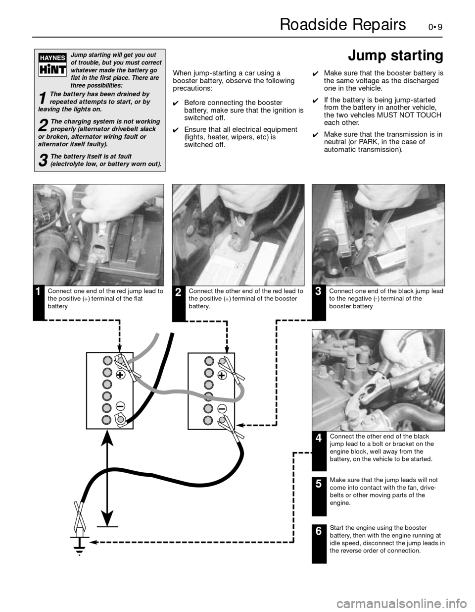
Connect one end of the red jump lead to
the positive (+) terminal of the flat
batteryConnect the other end of the red lead to
the positive (+) terminal of the booster
battery.Connect one end of the black jump lead
to the negative (-) terminal of the
booster battery
Connect the other end of the black
jump lead to a bolt or bracket on the
engine block, well away from the
battery, on the vehicle to be started.
123
4
Make sure that the jump leads will not
come into contact with the fan, drive-
belts or other moving parts of the
engine.5
Start the engine using the booster
battery, then with the engine running at
idle speed, disconnect the jump leads in
the reverse order of connection.6
Jump starting
Page 13 of 228

Tyre pressures (cold) - bars (psi)Front Rear
3-Series, E30
316 . . . . . . . . . . . . . . . . . . . . . . . . . . . . . . . . . . . . . . . . . . . . . . . . . . . 1.9 (28) 2.1 (30)
316i
Saloon . . . . . . . . . . . . . . . . . . . . . . . . . . . . . . . . . . . . . . . . . . . . . . . 2.0 (29) 2.1 (30)
Estate . . . . . . . . . . . . . . . . . . . . . . . . . . . . . . . . . . . . . . . . . . . . . . . 2.0 (29) 2.2 (32)
318i . . . . . . . . . . . . . . . . . . . . . . . . . . . . . . . . . . . . . . . . . . . . . . . . . . . 1.8 (26) 1.9 (28)
320i . . . . . . . . . . . . . . . . . . . . . . . . . . . . . . . . . . . . . . . . . . . . . . . . . . . 1.9 (28) 2.0 (29)
325i . . . . . . . . . . . . . . . . . . . . . . . . . . . . . . . . . . . . . . . . . . . . . . . . . . . 2.2 (32) 2.3 (33)
5-Series, E28 (“old-shape”)
518 and 518i . . . . . . . . . . . . . . . . . . . . . . . . . . . . . . . . . . . . . . . . . . . . 2.0 (29) 2.0 (29)
525i and 528i . . . . . . . . . . . . . . . . . . . . . . . . . . . . . . . . . . . . . . . . . . . 2.2 (32) 2.2 (32)
535i and M535i . . . . . . . . . . . . . . . . . . . . . . . . . . . . . . . . . . . . . . . . . . 2.3 (33) 2.5 (36)
5-Series, E34 (“new-shape”)
518i . . . . . . . . . . . . . . . . . . . . . . . . . . . . . . . . . . . . . . . . . . . . . . . . . . . 2.0 (29) 2.0 (29)
520i . . . . . . . . . . . . . . . . . . . . . . . . . . . . . . . . . . . . . . . . . . . . . . . . . . . 2.2 (32) 2.1 (30)
525i, 530i and 535i . . . . . . . . . . . . . . . . . . . . . . . . . . . . . . . . . . . . . . . 2.0 (29) 2.3 (33)
Torque wrench settingsNm
Automatic transmission sump bolts
Three-speed . . . . . . . . . . . . . . . . . . . . . . . . . . . . . . . . . . . . . . . . . . . . 8 to 9
Four-speed . . . . . . . . . . . . . . . . . . . . . . . . . . . . . . . . . . . . . . . . . . . . . 5 to 7
Spark plugs
M10 engines . . . . . . . . . . . . . . . . . . . . . . . . . . . . . . . . . . . . . . . . . . . . 20 to 30
Except M10 engines . . . . . . . . . . . . . . . . . . . . . . . . . . . . . . . . . . . . . . 30 to 33
Oxygen sensor . . . . . . . . . . . . . . . . . . . . . . . . . . . . . . . . . . . . . . . . . . . . 30 to 33
Wheel bolts . . . . . . . . . . . . . . . . . . . . . . . . . . . . . . . . . . . . . . . . . . . . . . . 100
Lubricants and fluids
Component or system Lubricant type/specification
Engine . . . . . . . . . . . . . . . . . . . . . . . . . . . . . . . . . . . . . . . . . . . . . . . . . . Multigrade engine oil, viscositySAE 10W/40 to 20W/50, to API SG
Cooling system . . . . . . . . . . . . . . . . . . . . . . . . . . . . . . . . . . . . . . . . . . . Ethylene glycol-based antifreeze with corrosion inhibitors
Manual transmission* . . . . . . . . . . . . . . . . . . . . . . . . . . . . . . . . . . . . . . Gear oil, viscosity SAE 80 to API-GL4, or single-grade mineral-based
engine oil, viscosity SAE 20, 30 or 40 to API-SG
Automatic transmission . . . . . . . . . . . . . . . . . . . . . . . . . . . . . . . . . . . . Dexron ll type ATF
Final drive . . . . . . . . . . . . . . . . . . . . . . . . . . . . . . . . . . . . . . . . . . . . . . . BMW-approved hypoid gear oil, viscosity SAE 90**
Brake and clutch hydraulic systems . . . . . . . . . . . . . . . . . . . . . . . . . . Hydraulic brake fluid to SAE J 1703 or DOT 4
Power steering . . . . . . . . . . . . . . . . . . . . . . . . . . . . . . . . . . . . . . . . . . . Dexron ll type ATF
* E34 520i & 525i with air conditioning, E34 530i & 535i - Dexron II type ATF)
** Only available in bulk; refer to your BMW dealer
Capacities*
1•3
1
Engine oil
M10 engines . . . . . . . . . . . . . . . . . . . . . . . . . . . . . . 4.0 litres
M20 engines . . . . . . . . . . . . . . . . . . . . . . . . . . . . . . 4.3 litres
M30 engines . . . . . . . . . . . . . . . . . . . . . . . . . . . . . . 5.8 litres
M40 engines . . . . . . . . . . . . . . . . . . . . . . . . . . . . . . 4.0 litres
Cooling system
M10 engines . . . . . . . . . . . . . . . . . . . . . . . . . . . . . . 7.0 litres
M20 engines . . . . . . . . . . . . . . . . . . . . . . . . . . . . . . 10.5 litres
M30 engines . . . . . . . . . . . . . . . . . . . . . . . . . . . . . . 12.0 litres
M40 engines . . . . . . . . . . . . . . . . . . . . . . . . . . . . . . 7.0 litres
Fuel tank
3-Series, E30
Saloon . . . . . . . . . . . . . . . . . . . . . . . . . . . . . . . . 55 litres (early),
64 litres (later)
Estate . . . . . . . . . . . . . . . . . . . . . . . . . . . . . . . . . 63 litres (early),
70 litres (later)
5-Series
E28 (“old-shape”) . . . . . . . . . . . . . . . . . . . . . . . . 70 litres
E34 (“new-shape”) . . . . . . . . . . . . . . . . . . . . . . . 81 litresManual transmission
ZF . . . . . . . . . . . . . . . . . . . . . . . . . . . . . . . . . . . . . . 1.2 litres
Getrag . . . . . . . . . . . . . . . . . . . . . . . . . . . . . . . . . . 1.0 to 1.5 litres
Automatic transmission (refill)
3-speed . . . . . . . . . . . . . . . . . . . . . . . . . . . . . . . . . 2.0 litres
4-speed . . . . . . . . . . . . . . . . . . . . . . . . . . . . . . . . . 3.0 litres
Final drive capacity (drain and refill)
3-Series, E30 . . . . . . . . . . . . . . . . . . . . . . . . . . . . . 0.9 litres
5-Series, E28 (“old-shape”) . . . . . . . . . . . . . . . . . . 0.9 litres
5-Series, E34 (“new-shape”) . . . . . . . . . . . . . . . . . 1.7 litres
*All capacities approximate
Servicing Specifications
Page 17 of 228
1 Introduction
This Chapter is designed to help the home
mechanic maintain his or her vehicle with the
goals of maximum performance, economy,
safety and reliability in mind. Included is a
master maintenance schedule, followed by
procedures dealing specifically with each item
on the schedule. Visual checks, adjustments,
component renewal and other helpful items
are included. Refer to the accompanying
illustrations of the engine compartment and
the underside of the vehicle for the locations
of various components. Servicing the vehicle,
in accordance with the mileage/time
maintenance schedule and the step-by-step
procedures, will result in a planned
maintenance programme that should produce
a long and reliable service life. Keep in mind
that it is a comprehensive plan, so maintaining
some items but not others at specified
intervals, will not produce the same results.
2 Routine maintenance
As you service the vehicle, you will discover
that many of the procedures can - and should
- be grouped together, because of the nature
of the particular procedure you’re performing,
or because of the close proximity of two
otherwise-unrelated components to one
another. For example, if the vehicle is raised
for chassis lubrication, you should inspect the
exhaust, suspension, steering and fuelsystems while you’re under the vehicle. When
the wheels are removed for other work, it
makes good sense to check the brakes, since
the wheels are already removed. Finally, let’s
suppose you have to borrow a torque wrench.
Even if you only need it to tighten the spark
plugs, you might as well check the torque of
as many critical nuts and bolts as time allows.
The first step in this maintenance
programme is to prepare yourself before the
actual work begins. Read through all the
procedures you’re planning to do, then gather
up all the parts and tools needed. If it looks
like you might run into problems during a
particular job, seek advice from a mechanic or
an experienced do-it-yourselfer.
3 Engine “tune-up”-
general information
The term “tune-up” is used in this manual to
represent a combination of individual
operations rather than one specific procedure.
If, from the time the vehicle is new, the
routine maintenance schedule is followed
closely, and frequent checks are made of fluid
levels and high-wear items, as suggested
throughout this manual, the engine will be
kept in relatively good running condition, and
the need for additional work will be minimised.
More likely than not, however, there will be
times when the engine is running poorly due
to a lack of regular maintenance. This is even
more likely if a used vehicle, which has not
received regular and frequent maintenance
checks, is purchased. In such cases, an
engine tune-up will be needed outside of the
regular maintenance intervals. The first step in any tune-up or diagnostic
procedure to help correct a poor-running
engine is a cylinder compression check. A
compression check (see Chapter 2B) will help
determine the condition of internal engine
components, and should be used as a guide
for tune-up and repair procedures. If, for
instance, a compression check indicates
serious internal engine wear, a conventional
tune-up will not improve the performance of
the engine, and would be a waste of time and
money. Because of its importance, the
compression check should be done by
someone with the right equipment, and the
knowledge to use it properly.
The following procedures are those most
often needed to bring a generally poor-
running engine back into a proper state of
tune.
Minor tune-up
Check all engine-related fluids (Section 4)
Check all underbonnet hoses (Section 10)
Check and adjust the drivebelts (Sec-
tion 11)
Clean, inspect and test the battery (Sec-
tion 13)
Renew the spark plugs (Section 14)
Inspect the spark plug HT leads, distributor
cap and rotor (Section 15)
Check the air filter (Section 20)
Check the cooling system (Section 22)
Major tune-up
All items listed under minor tune-up, plus . . .
Check the ignition system (see Chapter 5)
Check the charging system (see Chapter 5)
Check the fuel system (see Chapter 4)
Renew the spark plug HT leads, distributor
cap and rotor (Section 15)
1•7
1
Routine Maintenance
Weekly checks
4 Fluid level checks
1
Note:The following are fluid level checks to
be done on a 250-mile or weekly basis.
Additional fluid level checks can be found in
specific maintenance procedures which
follow. Regardless of intervals, be alert to fluid
leaks under the vehicle, which would indicate
a fault to be corrected immediately.
1Fluids are an essential part of the
lubrication, cooling, brake and windscreen
washer systems. Because the fluids gradually
become depleted and/or contaminated during
normal operation of the vehicle, they must be
periodically replenished. See “Lubricants and
fluids”at the beginning of this Chapter before
adding fluid to any of the following
components. Note:The vehicle must be on
level ground when any fluid levels are
checked.
Engine oil
2Engine oil is checked with a dipstick, which
is located on the side of the engine (refer to
the underbonnet illustrations in this Chapter
for dipstick location). The dipstick extends
through a metal tube down into the sump.
3The engine oil should be checked before
the vehicle has been driven, or at least
15 minutes after the engine has been shut off.
4Pull the dipstick out of the tube, and wipe
all of the oil away from the end with a clean
rag or paper towel. Insert the clean dipstick all
the way back into the tube, and pull it out
again. Note the oil at the end of the dipstick.
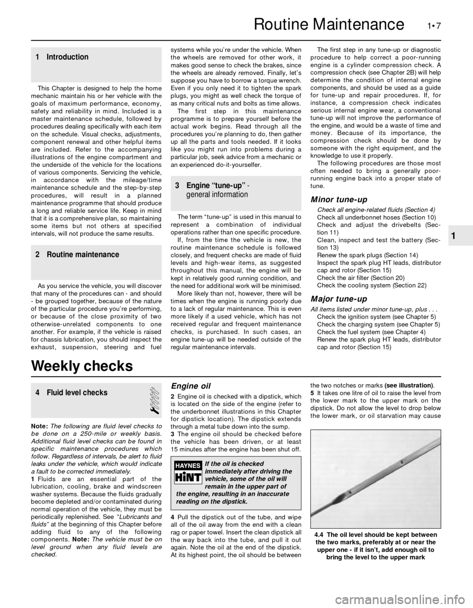
At its highest point, the oil should be betweenthe two notches or marks (see illustration).
5It takes one litre of oil to raise the level from
the lower mark to the upper mark on the
dipstick. Do not allow the level to drop below
the lower mark, or oil starvation may cause
4.4 The oil level should be kept between
the two marks, preferably at or near the
upper one - if it isn’t, add enough oil to
bring the level to the upper mark
If the oil is checked
immediately after driving the
vehicle, some of the oil will
remain in the upper part of
the engine, resulting in an inaccurate
reading on the dipstick.
Page 21 of 228
Every 6000 miles or 6 months, whichever comes first
1•11
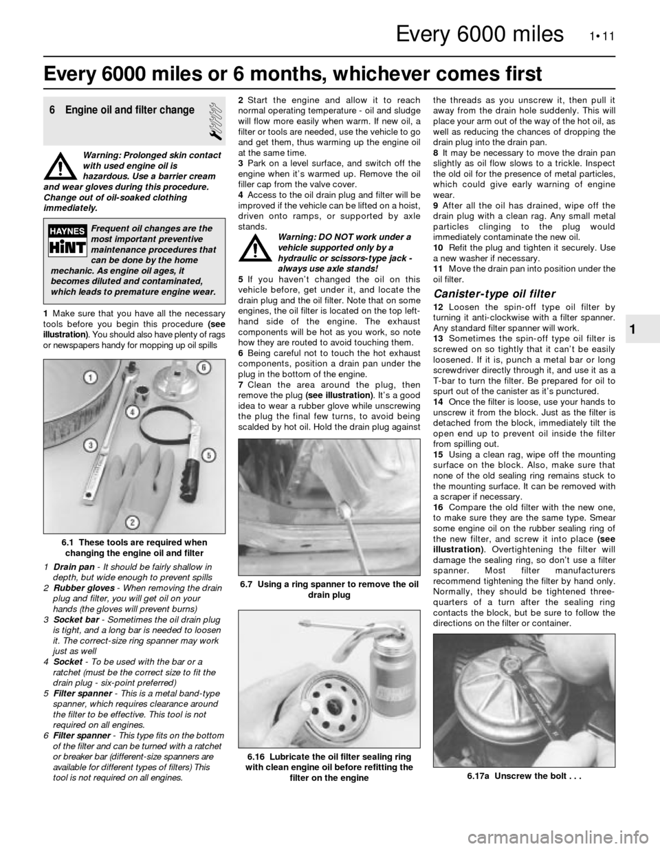
6.17a Unscrew the bolt . . .
1
Every 6000 miles
6 Engine oil and filter change
1
Warning: Prolonged skin contact
with used engine oil is
hazardous. Use a barrier cream
and wear gloves during this procedure.
Change out of oil-soaked clothing
immediately.
1Make sure that you have all the necessary
tools before you begin this procedure (see
illustration). You should also have plenty of rags
or newspapers handy for mopping up oil spills2Start the engine and allow it to reach
normal operating temperature - oil and sludge
will flow more easily when warm. If new oil, a
filter or tools are needed, use the vehicle to go
and get them, thus warming up the engine oil
at the same time.
3Park on a level surface, and switch off the
engine when it’s warmed up. Remove the oil
filler cap from the valve cover.
4Access to the oil drain plug and filter will be
improved if the vehicle can be lifted on a hoist,
driven onto ramps, or supported by axle
stands.
Warning: DO NOT work under a
vehicle supported only by a
hydraulic or scissors-type jack -
always use axle stands!
5If you haven’t changed the oil on this
vehicle before, get under it, and locate the
drain plug and the oil filter. Note that on some
engines, the oil filter is located on the top left-
hand side of the engine. The exhaust
components will be hot as you work, so note
how they are routed to avoid touching them.
6Being careful not to touch the hot exhaust
components, position a drain pan under the
plug in the bottom of the engine.
7Clean the area around the plug, then
remove the plug (see illustration). It’s a good
idea to wear a rubber glove while unscrewing
the plug the final few turns, to avoid being
scalded by hot oil. Hold the drain plug againstthe threads as you unscrew it, then pull it
away from the drain hole suddenly. This will
place your arm out of the way of the hot oil, as
well as reducing the chances of dropping the
drain plug into the drain pan.
8It may be necessary to move the drain pan
slightly as oil flow slows to a trickle. Inspect
the old oil for the presence of metal particles,
which could give early warning of engine
wear.
9After all the oil has drained, wipe off the
drain plug with a clean rag. Any small metal
particles clinging to the plug would
immediately contaminate the new oil.
10Refit the plug and tighten it securely. Use
a new washer if necessary.
11Move the drain pan into position under the
oil filter.
Canister-type oil filter
12Loosen the spin-off type oil filter by
turning it anti-clockwise with a filter spanner.
Any standard filter spanner will work.
13Sometimes the spin-off type oil filter is
screwed on so tightly that it can’t be easily
loosened. If it is, punch a metal bar or long
screwdriver directly through it, and use it as a
T-bar to turn the filter. Be prepared for oil to
spurt out of the canister as it’s punctured.
14Once the filter is loose, use your hands to
unscrew it from the block. Just as the filter is
detached from the block, immediately tilt the
open end up to prevent oil inside the filter
from spilling out.
15Using a clean rag, wipe off the mounting
surface on the block. Also, make sure that
none of the old sealing ring remains stuck to
the mounting surface. It can be removed with
a scraper if necessary.
16Compare the old filter with the new one,
to make sure they are the same type. Smear
some engine oil on the rubber sealing ring of
the new filter, and screw it into place (see
illustration). Overtightening the filter will
damage the sealing ring, so don’t use a filter
spanner. Most filter manufacturers
recommend tightening the filter by hand only.
Normally, they should be tightened three-
quarters of a turn after the sealing ring
contacts the block, but be sure to follow the
directions on the filter or container.
6.1 These tools are required when
changing the engine oil and filter
1 Drain pan- It should be fairly shallow in
depth, but wide enough to prevent spills
2 Rubber gloves- When removing the drain
plug and filter, you will get oil on your
hands (the gloves will prevent burns)
3 Socket bar - Sometimes the oil drain plug
is tight, and a long bar is needed to loosen
it. The correct-size ring spanner may work
just as well
4 Socket- To be used with the bar or a
ratchet (must be the correct size to fit the
drain plug - six-point preferred)
5 Filter spanner - This is a metal band-type
spanner, which requires clearance around
the filter to be effective. This tool is not
required on all engines.
6 Filter spanner- This type fits on the bottom
of the filter and can be turned with a ratchet
or breaker bar (different-size spanners are
available for different types of filters) This
tool is not required on all engines.
6.7 Using a ring spanner to remove the oil
drain plug
6.16 Lubricate the oil filter sealing ring
with clean engine oil before refitting the
filter on the engine
Frequent oil changes are the
most important preventive
maintenance procedures that
can be done by the home
mechanic. As engine oil ages, it
becomes diluted and contaminated,
which leads to premature engine wear.
Page 22 of 228
Cartridge-type oil filter
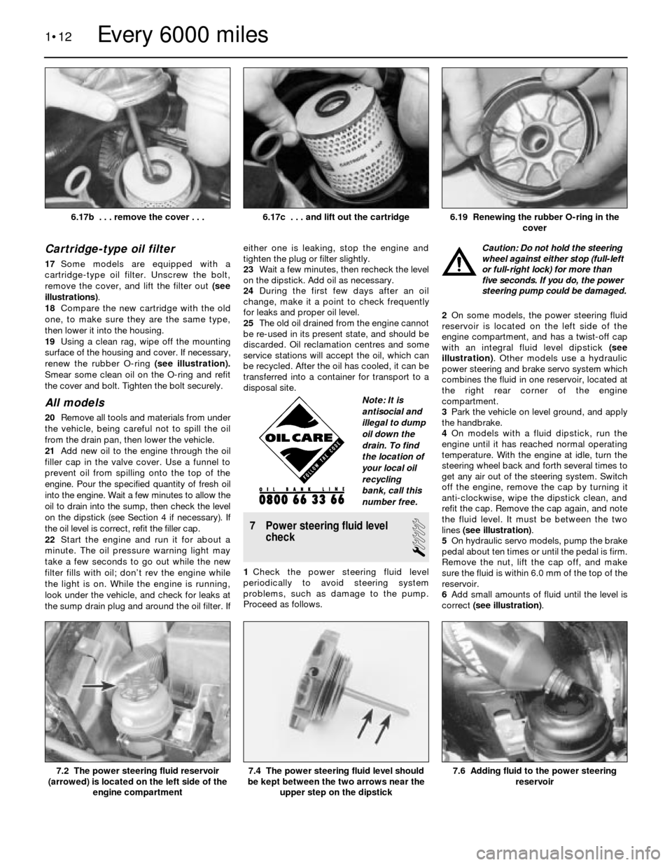
17Some models are equipped with a
cartridge-type oil filter. Unscrew the bolt,
remove the cover, and lift the filter out (see
illustrations).
18Compare the new cartridge with the old
one, to make sure they are the same type,
then lower it into the housing.
19Using a clean rag, wipe off the mounting
surface of the housing and cover. If necessary,
renew the rubber O-ring (see illustration).
Smear some clean oil on the O-ring and refit
the cover and bolt. Tighten the bolt securely.
All models
20Remove all tools and materials from under
the vehicle, being careful not to spill the oil
from the drain pan, then lower the vehicle.
21Add new oil to the engine through the oil
filler cap in the valve cover. Use a funnel to
prevent oil from spilling onto the top of the
engine. Pour the specified quantity of fresh oil
into the engine. Wait a few minutes to allow the
oil to drain into the sump, then check the level
on the dipstick (see Section 4 if necessary). If
the oil level is correct, refit the filler cap.
22Start the engine and run it for about a
minute. The oil pressure warning light may
take a few seconds to go out while the new
filter fills with oil; don’t rev the engine while
the light is on. While the engine is running,
look under the vehicle, and check for leaks at
the sump drain plug and around the oil filter. Ifeither one is leaking, stop the engine and
tighten the plug or filter slightly.
23Wait a few minutes, then recheck the level
on the dipstick. Add oil as necessary.
24During the first few days after an oil
change, make it a point to check frequently
for leaks and proper oil level.
25The old oil drained from the engine cannot
be re-used in its present state, and should be
discarded. Oil reclamation centres and some
service stations will accept the oil, which can
be recycled. After the oil has cooled, it can be
transferred into a container for transport to a
disposal site.
7 Power steering fluid level
check
1
1Check the power steering fluid level
periodically to avoid steering system
problems, such as damage to the pump.
Proceed as follows.Caution: Do not hold the steering
wheel against either stop (full-left
or full-right lock) for more than
five seconds. If you do, the power
steering pump could be damaged.
2On some models, the power steering fluid
reservoir is located on the left side of the
engine compartment, and has a twist-off cap
with an integral fluid level dipstick (see
illustration). Other models use a hydraulic
power steering and brake servo system which
combines the fluid in one reservoir, located at
the right rear corner of the engine
compartment.
3Park the vehicle on level ground, and apply
the handbrake.
4On models with a fluid dipstick, run the
engine until it has reached normal operating
temperature. With the engine at idle, turn the
steering wheel back and forth several times to
get any air out of the steering system. Switch
off the engine, remove the cap by turning it
anti-clockwise, wipe the dipstick clean, and
refit the cap. Remove the cap again, and note
the fluid level. It must be between the two
lines (see illustration).
5On hydraulic servo models, pump the brake
pedal about ten times or until the pedal is firm.
Remove the nut, lift the cap off, and make
sure the fluid is within 6.0 mm of the top of the
reservoir.
6Add small amounts of fluid until the level is
correct (see illustration).
1•12
7.6 Adding fluid to the power steering
reservoir7.4 The power steering fluid level should
be kept between the two arrows near the
upper step on the dipstick7.2 The power steering fluid reservoir
(arrowed) is located on the left side of the
engine compartment
6.19 Renewing the rubber O-ring in the
cover6.17c . . . and lift out the cartridge
Every 6000 miles
6.17b . . . remove the cover . . .
Note: It is
antisocial and
illegal to dump
oil down the
drain. To find
the location of
your local oil
recycling
bank, call this
number free.
Page 23 of 228
Caution: Do not overfill the
reservoir. If too much fluid is
added, remove the excess with a
clean syringe. Refit the cap.
7If frequent topping-up is needed, check the
power steering hoses and connections for
leaks and wear (see Section 10).
8Check the condition and tension of the
drivebelt (see Section 11).
8 Automatic transmission fluid
level check
1
Caution: The use of transmission
fluid other than the type listed in
this Chapter’s Specifications
could result in transmission
malfunctions or failure.
1The automatic transmission fluid should be
carefully maintained. Low fluid level can lead
to slipping or loss of drive, while overfilling
can cause foaming and loss of fluid. Either
condition can cause transmission damage.
2Since transmission fluid expands as it heats
up, the fluid level should only be checked
when the transmission is warm (at normal
operating temperature). If the vehicle has just
been driven over 20 miles (32 km), the
transmission can be considered warm. You
can also check the fluid level when the
transmission is cold. If the vehicle has not
been driven for over five hours and the fluid is
about room temperature (20°C), the
transmission is cold. However, the fluid level
is normally checked with the transmission
warm, to ensure accurate results.
Caution: If the vehicle has just
been driven for a long time at
high speed or in city traffic, in hot
weather, or if it has been pulling
a trailer, an accurate fluid level reading
cannot be obtained. Allow the trans-
mission to cool down for about 30 minutes.
3Immediately after driving the vehicle, park it
on a level surface, apply the handbrake and
start the engine. While the engine is idling,
depress the brake pedal and move theselector lever through all the gear ranges,
beginning and ending in Park.
4The automatic transmission dipstick tube is
located in the left rear corner of the engine
compartment.
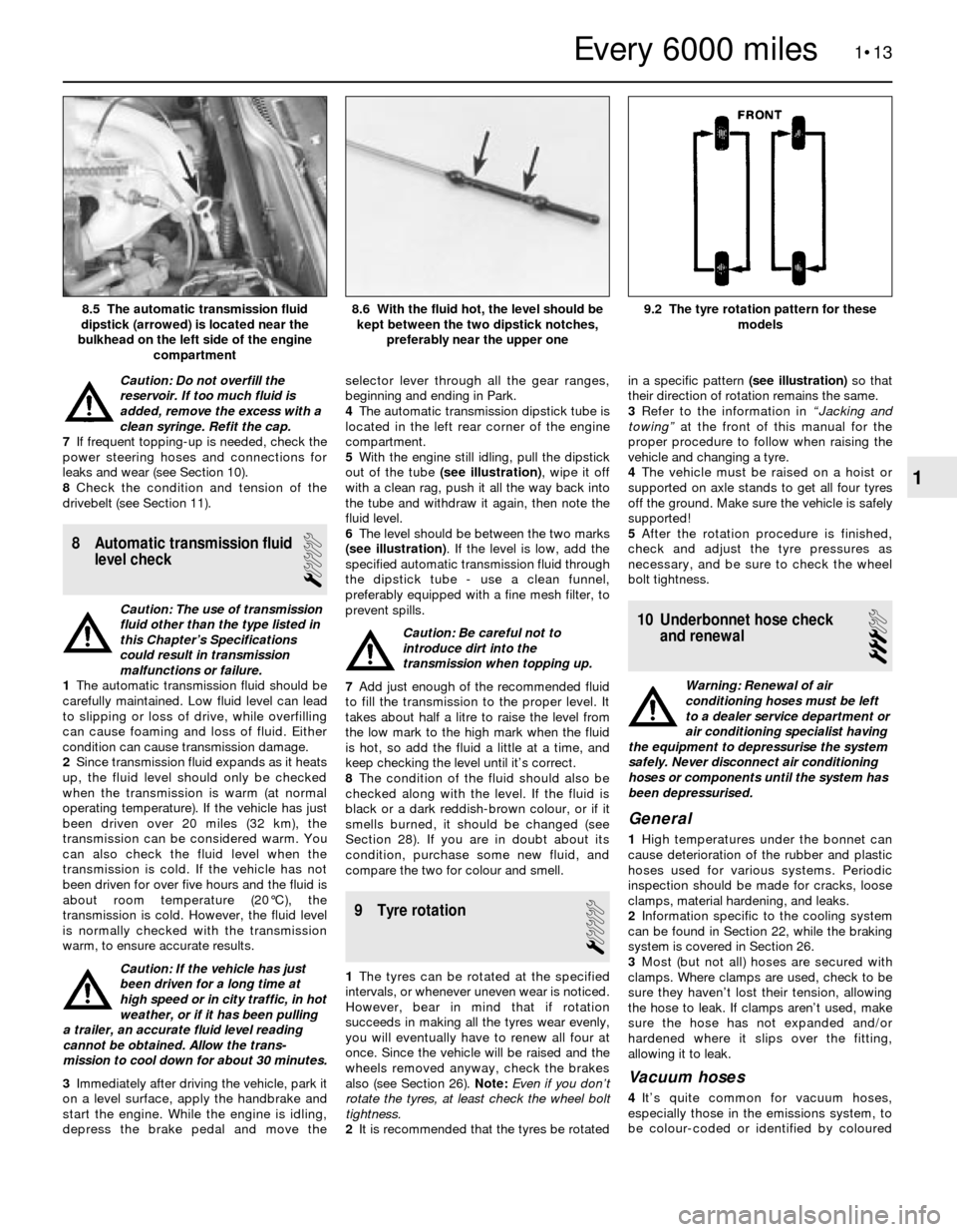
5With the engine still idling, pull the dipstick
out of the tube (see illustration), wipe it off
with a clean rag, push it all the way back into
the tube and withdraw it again, then note the
fluid level.
6The level should be between the two marks
(see illustration). If the level is low, add the
specified automatic transmission fluid through
the dipstick tube - use a clean funnel,
preferably equipped with a fine mesh filter, to
prevent spills.
Caution: Be careful not to
introduce dirt into the
transmission when topping up.
7Add just enough of the recommended fluid
to fill the transmission to the proper level. It
takes about half a litre to raise the level from
the low mark to the high mark when the fluid
is hot, so add the fluid a little at a time, and
keep checking the level until it’s correct.
8The condition of the fluid should also be
checked along with the level. If the fluid is
black or a dark reddish-brown colour, or if it
smells burned, it should be changed (see
Section 28). If you are in doubt about its
condition, purchase some new fluid, and
compare the two for colour and smell.
9 Tyre rotation
1
1The tyres can be rotated at the specified
intervals, or whenever uneven wear is noticed.
However, bear in mind that if rotation
succeeds in making all the tyres wear evenly,
you will eventually have to renew all four at
once. Since the vehicle will be raised and the
wheels removed anyway, check the brakes
also (see Section 26). Note: Even if you don’t
rotate the tyres, at least check the wheel bolt
tightness.
2It is recommended that the tyres be rotatedin a specific pattern (see illustration)so that
their direction of rotation remains the same.
3Refer to the information in “Jacking and
towing”at the front of this manual for the
proper procedure to follow when raising the
vehicle and changing a tyre.
4The vehicle must be raised on a hoist or
supported on axle stands to get all four tyres
off the ground. Make sure the vehicle is safely
supported!
5After the rotation procedure is finished,
check and adjust the tyre pressures as
necessary, and be sure to check the wheel
bolt tightness.
10 Underbonnet hose check
and renewal
3
Warning: Renewal of air
conditioning hoses must be left
to a dealer service department or
air conditioning specialist having
the equipment to depressurise the system
safely. Never disconnect air conditioning
hoses or components until the system has
been depressurised.
General
1High temperatures under the bonnet can
cause deterioration of the rubber and plastic
hoses used for various systems. Periodic
inspection should be made for cracks, loose
clamps, material hardening, and leaks.
2Information specific to the cooling system
can be found in Section 22, while the braking
system is covered in Section 26.
3Most (but not all) hoses are secured with
clamps. Where clamps are used, check to be
sure they haven’t lost their tension, allowing
the hose to leak. If clamps aren’t used, make
sure the hose has not expanded and/or
hardened where it slips over the fitting,
allowing it to leak.
Vacuum hoses
4It’s quite common for vacuum hoses,
especially those in the emissions system, to
be colour-coded or identified by coloured
1•13
9.2 The tyre rotation pattern for these
models8.6 With the fluid hot, the level should be
kept between the two dipstick notches,
preferably near the upper one8.5 The automatic transmission fluid
dipstick (arrowed) is located near the
bulkhead on the left side of the engine
compartment
1
Every 6000 miles
Page 24 of 228
stripes moulded into them. Various systems
require hoses with different wall thicknesses,
collapse resistance and temperature
resistance. When fitting new hoses, be sure
the new ones are made of the same material.
5Often the only effective way to check a
hose is to remove it completely from the
vehicle. If more than one hose is removed, be
sure to label the hoses and fittings to ensure
correct refitting.
6When checking vacuum hoses, be sure to
include any plastic T-fittings in the check.
Inspect the connections for cracks which
could cause leakage.
7A small piece of vacuum hose can be used
as a stethoscope to detect vacuum leaks.
Hold one end of the hose to your ear and
probe around vacuum hoses and fittings,
listening for the “hissing” sound characteristic
of a vacuum leak.
Warning: When probing with the
vacuum hose stethoscope, be
careful not to touch moving
engine components such as the
drivebelt, cooling fan, etc.
Fuel hoses
Warning: There are certain
precautions which must be taken
when servicing or inspecting fuel
system components. Work in a
well-ventilated area, and do not allow open
flames (cigarettes, appliance pilot lights,
etc.) or bare light bulbs near the work
area. Mop up any spills immediately, and
do not store fuel-soaked rags where they
could ignite. If you spill any fuel on your
skin, rinse it off immediately with soap and
water. When you perform any kind of work
on the fuel system, wear safety glasses,
and have a fire extinguisher on hand.
8The fuel hoses are usually under pressure,
so if any fuel hoses are to be disconnected,
be prepared to catch spilled fuel.
Warning: On vehicles equipped
with fuel injection, you must
depressurise the fuel system
before servicing the fuel hoses.
Refer to Chapter 4 for details.9Check all rubber fuel hoses for deterioration
and chafing. Check especially for cracks in
areas where the hose bends, and just before
connectors, such as where a hose attaches to
the fuel pump or fuel filter, for example.
10Only high-quality fuel hose should be
used. Never, under any circumstances, use
unreinforced vacuum hose, clear plastic
tubing or water hose for fuel hoses.
11Band-type clamps are commonly used on
fuel hoses. These clamps often lose their
tension over a period of time, and can be
“sprung” during removal. Renew all band-type
clamps with screw clamps whenever a hose is
renewed.
Metal lines
12Sections of metal line are often used
between the fuel pump and fuel injection
system. Check carefully to make sure the line
isn’t bent, crimped or cracked.
13If a section of metal line must be renewed,
use seamless steel tubing only, since copper
and aluminium tubing do not have the
strength necessary to withstand the vibration
caused by the engine.
14Check the metal brake lines where they
enter the master cylinder and brake
proportioning or ABS unit (if used) for cracks
in the lines and loose fittings. Any sign of
brake fluid leakage calls for an immediate
thorough inspection of the braking system.
Power steering hoses
15Check the power steering hoses for leaks,
loose connections and worn clamps. Tighten
loose connections. Worn clamps or leaky
hoses should be renewed.
11 Drivebelt check, adjustment
and renewal
1
Check
1The drivebelts, sometimes called V-belts or
simply “fan” belts, are located at the front of
the engine, and play an important role in the
overall operation of the vehicle and itscomponents. Due to their function and
material make-up, the belts are prone to
failure after a period of time, and should be
inspected and adjusted periodically to prevent
major engine damage.
2The number of belts used on a particular
vehicle depends on the accessories fitted.
Drivebelts are used to turn the alternator,
power steering pump, water pump, and air
conditioning compressor. Depending on the
pulley arrangement, a single belt may be used
to drive more than one of these components.
3With the engine switched off, open the
bonnet and locate the various belts at the
front of the engine. Using your fingers (and a
torch, if necessary), move along the belts,
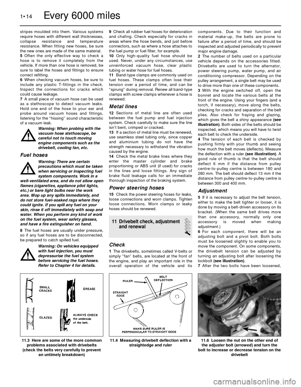
checking for cracks and separation of the belt
plies. Also check for fraying and glazing,
which gives the belt a shiny appearance (see
illustration). Both sides of the belts should be
inspected, which means you will have to twist
each belt to check the underside.
4The tension of each belt is checked by
pushing firmly with your thumb and seeing
how much the belt moves (deflects). Measure
the deflection with a ruler (see illustration). A
good rule of thumb is that the belt should
deflect 6 mm if the distance from pulley
centre-to-pulley centre is between 180 and
280 mm. The belt should deflect 13 mm if the
distance from pulley centre-to-pulley centre is
between 300 and 400 mm.
Adjustment
5If it is necessary to adjust the belt tension,
either to make the belt tighter or looser, it is
done by moving a belt-driven accessory on its
bracket. (When the same belt drives more
than one accessory, normally only one
accessory is moved when making
adjustment.)
6For each component, there will be an
adjusting bolt and a pivot bolt. Both bolts
must be loosened slightly to enable you to
move the component. On some components,
the drivebelt tension can be adjusted by
turning an adjusting bolt after loosening the
lockbolt (see illustration).
7After the two bolts have been loosened,
1•14
11.6 Loosen the nut on the other end of
the adjuster bolt (arrowed) and turn the
bolt to increase or decrease tension on the
drivebelt11.4 Measuring drivebelt deflection with a
straightedge and ruler11.3 Here are some of the more common
problems associated with drivebelts
(check the belts very carefully to prevent
an untimely breakdown)
Every 6000 miles
Page 25 of 228
move the component away from the engine to
tighten the belt, or towards the engine to
loosen the belt. Hold the accessory in
position, and check the belt tension. If it is
correct, tighten the two bolts until just tight,
then recheck the tension. If the tension is still
correct, tighten the bolts.
8It will often be necessary to use some sort
of lever to move the accessory while the belt
is adjusted. If this must be done to gain the
proper leverage, be very careful not to
damage the component being moved, or the
part being prised against.
Renewal
9To renew a belt, follow the instructions
above for adjustment, but remove the belt
from the pulleys.
10In some cases, you will have to remove
more than one belt, because of their
arrangement on the front of the engine.
Because of this, and the fact that belts will
tend to fail at the same time, it is wise to
renew all belts together. Mark each belt and
its appropriate pulley groove, so all renewed
belts can be fitted in their proper positions.
11It is a good idea to take the old belts with
you when buying new ones, in order to make
a direct comparison for length, width and
design.
12Recheck the tension of new belts after a
few hundred miles.
12 Engine idle speed and CO
level check and adjustment
4
Note:The engine should be at normal
operating temperature, with correct ignition
timing and valve clearances (where
adjustable). The air filter should be in good
condition, and all electrical components
(including the air conditioning, where fitted)
should be switched off.
Carburettor
1Connect a tachometer and exhaust gas
analyser (CO meter) to the engine.
2Start the engine and allow it to idle.
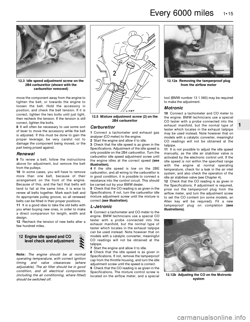
3Check that the idle speed is as given in the
Specifications. Adjustment of the idle speed is
only possible on the 2B4 carburettor. Turn the
carburettor idle speed adjustment screw until
the engine idles at the correct speed (see
illustration).
4If the idle speed is low on the 2BE
carburettor, and all wiring to the carburettor is
in good condition, it is possible to connect a
resistance into the control circuit. This should
be carried out by your BMW dealer.
5Check that the CO reading is as given in the
Specifications. If not, turn the carburettor idle
mixture adjustment screw until the mixture is
correct (see illustration).
L-Jetronic
6Connect a tachometer and CO meter to the
engine. BMW technicians use a special CO
tester with a probe connected into the
exhaust manifold, but the normal type of
tester which locates in the exhaust tailpipe
can be used instead. Note however that on
models with a catalytic converter, meaningful
CO readings will not be obtained at the
tailpipe.
7Start the engine and allow it to idle.
8Check that the idle speed is as given in
Specifications. If not, remove the tamperproof
cap from the throttle housing, and turn the idle
adjustment screw until the speed is correct.
9Check that the CO reading is as given in the
Specifications. The mixture control screw is
located on the airflow meter, and a specialtool (BMW number 13 1 060) may be required
to make the adjustment.
Motronic
10Connect a tachometer and CO meter to
the engine. BMW technicians use a special
CO tester with a probe connected into the
exhaust manifold, but the normal type of
tester which locates in the exhaust tailpipe
may be used instead. Note however that on
models with a catalytic converter, meaningful
CO readings will not be obtained at the
tailpipe.
11It is not possible to adjust the idle speed
manually, as the idle air stabiliser valve is
activated by the electronic control unit. If the
idle speed is not within the specified range
with the engine at normal operating
temperature, check for a leak in the air inlet
system, and also check the operation of the
idle air stabiliser valve (see Chapter 4).
12Check that the CO reading is as given in
the Specifications. If adjustment is required,
prise out the tamperproof plug from the
airflow meter, and turn the adjustment screw
to set the CO content (on some models, an
Allen key will be required). Fit a new
tamperproof plug on completion (see
illustrations).
1•15
12.12a Removing the tamperproof plug
from the airflow meter
12.5 Mixture adjustment screw (2) on the
2B4 carburettor
12.3 Idle speed adjustment screw on the
2B4 carburettor (shown with the
carburettor removed)
12.12b Adjusting the CO on the Motronic
system
1
Every 6000 miles