Rear BMW 3 SERIES 1989 E30 User Guide
[x] Cancel search | Manufacturer: BMW, Model Year: 1989, Model line: 3 SERIES, Model: BMW 3 SERIES 1989 E30Pages: 228, PDF Size: 7.04 MB
Page 36 of 228
the lubricant will be hot, it would be wise to
wear rubber gloves.
3Raise the vehicle and place it on axle
stands. Make sure it is safely supported, and
as level as possible.
4Move the necessary equipment under the
vehicle, being careful not to touch any of the
hot exhaust components.
5Place the drain pan under the transmission,
and remove the filler/level plug from the side
of the transmission. Loosen the drain plug
(see illustration).
6Carefully remove the drain plug. Be careful
not to burn yourself on the lubricant.
7Allow the lubricant to drain completely.
Clean the drain plug thoroughly, then refit and
tighten it securely.
8Refer to Section 16 and fill the transmission
with new lubricant, then refit the filler/level
plug, tightening it securely.
9Lower the vehicle. Check for leaks at the
drain plug after the first few miles of driving.
32 Differential lubricant change
1
1Drive the vehicle for several miles to warm
up the differential lubricant, then raise the
vehicle and support it securely on axle stands.
2Move a drain pan, rags, newspapers and an
Allen key under the vehicle. Since the
lubricant will be hot, wear rubber gloves to
prevent burns.
3Remove the filler/level plug from the
differential; this is the upper of the two plugs.
4With the drain pan under the differential,
loosen the drain plug; this is the lower of the
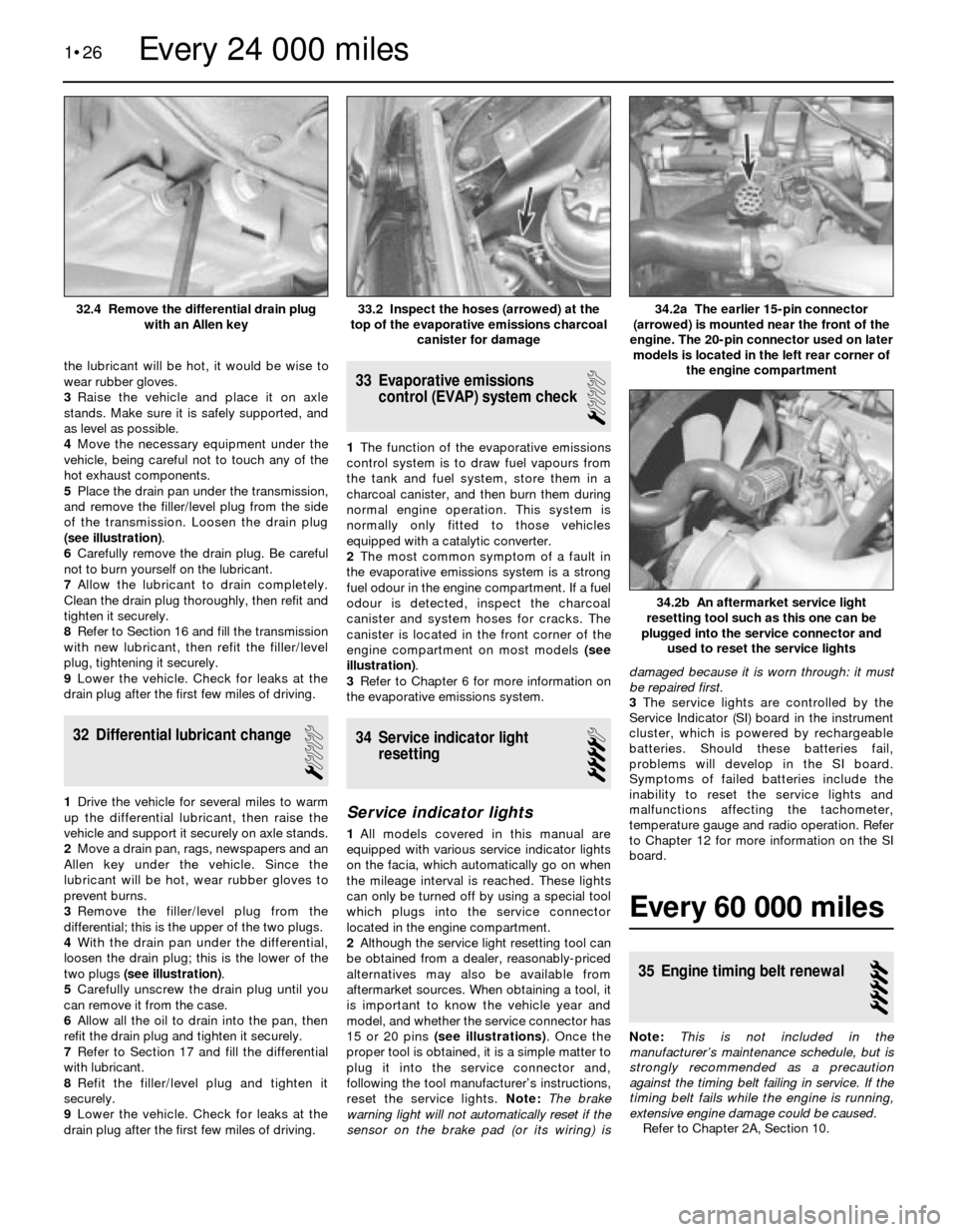
two plugs (see illustration).
5Carefully unscrew the drain plug until you
can remove it from the case.
6Allow all the oil to drain into the pan, then
refit the drain plug and tighten it securely.
7Refer to Section 17 and fill the differential
with lubricant.
8Refit the filler/level plug and tighten it
securely.
9Lower the vehicle. Check for leaks at the
drain plug after the first few miles of driving.
33 Evaporative emissions
control (EVAP) system check
1
1The function of the evaporative emissions
control system is to draw fuel vapours from
the tank and fuel system, store them in a
charcoal canister, and then burn them during
normal engine operation. This system is
normally only fitted to those vehicles
equipped with a catalytic converter.
2The most common symptom of a fault in
the evaporative emissions system is a strong
fuel odour in the engine compartment. If a fuel
odour is detected, inspect the charcoal
canister and system hoses for cracks. The
canister is located in the front corner of the
engine compartment on most models (see
illustration).
3Refer to Chapter 6 for more information on
the evaporative emissions system.
34 Service indicator light
resetting
4
Service indicator lights
1All models covered in this manual are
equipped with various service indicator lights
on the facia, which automatically go on when
the mileage interval is reached. These lights
can only be turned off by using a special tool
which plugs into the service connector
located in the engine compartment.
2Although the service light resetting tool can
be obtained from a dealer, reasonably-priced
alternatives may also be available from
aftermarket sources. When obtaining a tool, it
is important to know the vehicle year and
model, and whether the service connector has
15 or 20 pins (see illustrations). Once the
proper tool is obtained, it is a simple matter to
plug it into the service connector and,
following the tool manufacturer’s instructions,
reset the service lights. Note: The brake
warning light will not automatically reset if the
sensor on the brake pad (or its wiring) isdamaged because it is worn through: it must
be repaired first.
3The service lights are controlled by the
Service Indicator (SI) board in the instrument
cluster, which is powered by rechargeable
batteries. Should these batteries fail,
problems will develop in the SI board.
Symptoms of failed batteries include the
inability to reset the service lights and
malfunctions affecting the tachometer,
temperature gauge and radio operation. Refer
to Chapter 12 for more information on the SI
board.
Every 60 000 miles
35 Engine timing belt renewal
5
Note:This is not included in the
manufacturer’s maintenance schedule, but is
strongly recommended as a precaution
against the timing belt failing in service. If the
timing belt fails while the engine is running,
extensive engine damage could be caused.
Refer to Chapter 2A, Section 10.
1•26
34.2b An aftermarket service light
resetting tool such as this one can be
plugged into the service connector and
used to reset the service lights
34.2a The earlier 15-pin connector
(arrowed) is mounted near the front of the
engine. The 20-pin connector used on later
models is located in the left rear corner of
the engine compartment33.2 Inspect the hoses (arrowed) at the
top of the evaporative emissions charcoal
canister for damage32.4 Remove the differential drain plug
with an Allen key
Every 24 000 miles
Page 37 of 228
2A
General
Displacement
3-series, E30 body style
316i (1988 to 1991) . . . . . . . . . . . . . . . . . . . . . . . . . . . . . . . . . . . 1596 cc (M40/4-cylinder engine)
316 (1983 to 1988) and 318i (1983 to 1987) . . . . . . . . . . . . . . . . 1766 cc (M10/4-cylinder engine)
318i (1987 1991) . . . . . . . . . . . . . . . . . . . . . . . . . . . . . . . . . . . . . 1796 cc (M40/4-cylinder engine)
320i (1987 to 1991) . . . . . . . . . . . . . . . . . . . . . . . . . . . . . . . . . . . 1990 cc (M20/6-cylinder engine)
325i (1987 to 1991) . . . . . . . . . . . . . . . . . . . . . . . . . . . . . . . . . . . 2494 cc (M20/6-cylinder engine)
5-series, E28 body style (“old-shape”)
518 (1981 to 1985) and 518i (1985 to 1988) . . . . . . . . . . . . . . . . 1766 cc (M10/4-cylinder engine)
525i (1981 to 1988) . . . . . . . . . . . . . . . . . . . . . . . . . . . . . . . . . . . 2494 cc (M30/6-cylinder engine)
528i (1981 to 1988) . . . . . . . . . . . . . . . . . . . . . . . . . . . . . . . . . . . 2788 cc (M30/6-cylinder engine)
535i (1985 to 1988) . . . . . . . . . . . . . . . . . . . . . . . . . . . . . . . . . . . 3430 cc (M30/6-cylinder engine)
M535i (1985 to 1988) . . . . . . . . . . . . . . . . . . . . . . . . . . . . . . . . . 3430 cc (M30/6-cylinder engine)
5-series, E34 body style (“new-shape”)
518i (1990 to 1993) . . . . . . . . . . . . . . . . . . . . . . . . . . . . . . . . . . . 1796 cc (M40/4-cylinder engine)
520i (1988 to 1991) . . . . . . . . . . . . . . . . . . . . . . . . . . . . . . . . . . . 1990 cc (M20/6-cylinder engine)
525i (1988 to 1991) . . . . . . . . . . . . . . . . . . . . . . . . . . . . . . . . . . . 2494 cc (M20/6-cylinder engine)
530i (1988 to 1991) . . . . . . . . . . . . . . . . . . . . . . . . . . . . . . . . . . . 2986 cc (M30/6-cylinder engine)
535i (1988 to 1993) . . . . . . . . . . . . . . . . . . . . . . . . . . . . . . . . . . . 3430 cc (M30/6-cylinder engine)
Firing order
Four-cylinder engine . . . . . . . . . . . . . . . . . . . . . . . . . . . . . . . . . . . . . . 1-3-4-2
Six-cylinder engine . . . . . . . . . . . . . . . . . . . . . . . . . . . . . . . . . . . . . . . 1-5-3-6-2-4
Lubrication system
Oil pressure (all engines)
At idle . . . . . . . . . . . . . . . . . . . . . . . . . . . . . . . . . . . . . . . . . . . . . . . . . 0.5 to 2.0 bars
Running (for example, at 4000 rpm) . . . . . . . . . . . . . . . . . . . . . . . . . . 4 bars or above (typically)
Oil pump rotor clearance - M40 engine
(body-to-outer rotor/outer rotor-to-inner rotor) . . . . . . . . . . . . . . . . . . . 0.12 mm to 0.20 mm
Oil pump pressure relief valve spring length - M40 engine . . . . . . . . . . 84.1 mm
Chapter 2 Part A:
In-car engine repair procedures
Camshaft - removal, inspection and refitting . . . . . . See Chapter 2B
Compression check . . . . . . . . . . . . . . . . . . . . . . . . . See Chapter 2B
Crankshaft rear oil seal - renewal . . . . . . . . . . . . . . . . . . . . . . . . . . . 16
Cylinder head - removal and refitting . . . . . . . . . . . . . . . . . . . . . . . . 12
Cylinder head - dismantling and inspection . . . . . . . See Chapter 2B
Drivebelt check, adjustment and renewal . . . . . . . . See Chapter 1
Engine - removal and refitting . . . . . . . . . . . . . . . . . See Chapter 2B
Engine mountings - check and renewal . . . . . . . . . . . . . . . . . . . . . . 17
Engine oil and filter change . . . . . . . . . . . . . . . . . . . See Chapter 1
Engine overhaul - general information . . . . . . . . . . . See Chapter 2B
Exhaust manifold - removal and refitting . . . . . . . . . . . . . . . . . . . . . 6
Flywheel/driveplate - removal and refitting . . . . . . . . . . . . . . . . . . . 15
Front oil seals - renewal . . . . . . . . . . . . . . . . . . . . . . . . . . . . . . . . . . 11
General information . . . . . . . . . . . . . . . . . . . . . . . . . . . . . . . . . . . . . 1
Intake manifold - removal and refitting . . . . . . . . . . . . . . . . . . . . . . . 5Oil pump - removal, inspection and refitting . . . . . . . . . . . . . . . . . . 14
Repair operations possible with the engine in the vehicle . . . . . . . . 2
Rocker arm and shaft assembly - dismantling, inspection
and reassembly . . . . . . . . . . . . . . . . . . . . . . . . . . . See Chapter 2B
Spark plug renewal . . . . . . . . . . . . . . . . . . . . . . . . . . See Chapter 1
Sump - removal and refitting . . . . . . . . . . . . . . . . . . . . . . . . . . . . . . 13
Timing belt and sprockets - removal, inspection and refitting . . . . . 10
Timing belt covers - removal and refitting . . . . . . . . . . . . . . . . . . . . . 9
Timing chain and sprockets - removal, inspection and refitting . . . . 8
Timing chain covers - removal and refitting . . . . . . . . . . . . . . . . . . . 7
Top Dead Centre (TDC) for No 1 piston - locating . . . . . . . . . . . . . . 3
Valve clearance check and adjustment . . . . . . . . . . . See Chapter 1
Valve cover - removal and refitting . . . . . . . . . . . . . . . . . . . . . . . . . . 4
Valves - servicing . . . . . . . . . . . . . . . . . . . . . . . . . . . See Chapter 2B
2A•1
Easy,suitable for
novice with little
experienceFairly easy,suitable
for beginner with
some experienceFairly difficult,
suitable for competent
DIY mechanic
Difficult,suitable for
experienced DIY
mechanicVery difficult,
suitable for expert
DIY or professional
Degrees of difficulty
Specifications Contents
Page 38 of 228
Torque wrench settingsNm
Timing chain tensioner plug . . . . . . . . . . . . . . . . . . . . . . . . . . . . . . . . . . 35
Timing belt tensioner bolts . . . . . . . . . . . . . . . . . . . . . . . . . . . . . . . . . . . 22
Camshaft sprocket-to-camshaft bolt
M10 and M30 engines . . . . . . . . . . . . . . . . . . . . . . . . . . . . . . . . . . . . 10
M20 and M40 engines . . . . . . . . . . . . . . . . . . . . . . . . . . . . . . . . . . . . 65
Flange to camshaft (M30 engine) . . . . . . . . . . . . . . . . . . . . . . . . . . . . 145
Timing chain or belt covers-to-engine
M6 bolts . . . . . . . . . . . . . . . . . . . . . . . . . . . . . . . . . . . . . . . . . . . . . . . 10
M8 bolts . . . . . . . . . . . . . . . . . . . . . . . . . . . . . . . . . . . . . . . . . . . . . . . 22
M10 (bolt size) bolts . . . . . . . . . . . . . . . . . . . . . . . . . . . . . . . . . . . . . . 47
Crankshaft pulley bolts . . . . . . . . . . . . . . . . . . . . . . . . . . . . . . . . . . . . . . 22
Crankshaft hub bolt or nut
M10 engine . . . . . . . . . . . . . . . . . . . . . . . . . . . . . . . . . . . . . . . . . . . . . 190
M20 engine . . . . . . . . . . . . . . . . . . . . . . . . . . . . . . . . . . . . . . . . . . . . . 410
M30 engine . . . . . . . . . . . . . . . . . . . . . . . . . . . . . . . . . . . . . . . . . . . . . 440
M40 engine . . . . . . . . . . . . . . . . . . . . . . . . . . . . . . . . . . . . . . . . . . . . . 310
Cylinder head bolts*
M10 four-cylinder engine
Stage 1 . . . . . . . . . . . . . . . . . . . . . . . . . . . . . . . . . . . . . . . . . . . . . . 60
Stage 2 (wait 15 minutes) . . . . . . . . . . . . . . . . . . . . . . . . . . . . . . . . Angle-tighten an additional 33°
Stage 3 (engine at normal operating temperature) . . . . . . . . . . . . . Angle-tighten an additional 25°
M20 six-cylinder engine with hex-head bolts
Stage 1 . . . . . . . . . . . . . . . . . . . . . . . . . . . . . . . . . . . . . . . . . . . . . . 40
Stage 2 (wait 15 minutes) . . . . . . . . . . . . . . . . . . . . . . . . . . . . . . . . 60
Stage 3 (engine at normal operating temperature) . . . . . . . . . . . . . Angle-tighten an additional 25°
M20 six-cylinder engine with Torx-head bolts
Stage 1 . . . . . . . . . . . . . . . . . . . . . . . . . . . . . . . . . . . . . . . . . . . . . . 30
Stage 2 . . . . . . . . . . . . . . . . . . . . . . . . . . . . . . . . . . . . . . . . . . . . . . Angle-tighten an additional 90°
Stage 3 . . . . . . . . . . . . . . . . . . . . . . . . . . . . . . . . . . . . . . . . . . . . . . Angle-tighten an additional 90°
M30 six-cylinder engine (up to and including 1987 model year)
Stage 1 . . . . . . . . . . . . . . . . . . . . . . . . . . . . . . . . . . . . . . . . . . . . . . 60
Stage 2 (wait 15 minutes) . . . . . . . . . . . . . . . . . . . . . . . . . . . . . . . . Angle-tighten an additional 33°
Stage 3 (engine at normal operating temperature) . . . . . . . . . . . . . Angle-tighten an additional 33°
M30 six-cylinder engine (from 1988 model year)
Stage 1 . . . . . . . . . . . . . . . . . . . . . . . . . . . . . . . . . . . . . . . . . . . . . . 60
Stage 2 (wait 20 minutes) . . . . . . . . . . . . . . . . . . . . . . . . . . . . . . . . 80
Stage 3 (engine at normal operating temperature) . . . . . . . . . . . . . Angle-tighten an additional 35°
M40 four-cylinder engine
Stage 1 . . . . . . . . . . . . . . . . . . . . . . . . . . . . . . . . . . . . . . . . . . . . . . 30
Stage 2 . . . . . . . . . . . . . . . . . . . . . . . . . . . . . . . . . . . . . . . . . . . . . . Angle-tighten an additional 90°
Stage 3 . . . . . . . . . . . . . . . . . . . . . . . . . . . . . . . . . . . . . . . . . . . . . . Angle-tighten an additional 90°
Intake manifold-to-cylinder head bolts
M8 bolt . . . . . . . . . . . . . . . . . . . . . . . . . . . . . . . . . . . . . . . . . . . . . . . . 22
M7 bolt . . . . . . . . . . . . . . . . . . . . . . . . . . . . . . . . . . . . . . . . . . . . . . . . 15
M6 bolt . . . . . . . . . . . . . . . . . . . . . . . . . . . . . . . . . . . . . . . . . . . . . . . . 10
Exhaust manifold-to-cylinder head nuts
M6 nut . . . . . . . . . . . . . . . . . . . . . . . . . . . . . . . . . . . . . . . . . . . . . . . . . 10
M7 nut . . . . . . . . . . . . . . . . . . . . . . . . . . . . . . . . . . . . . . . . . . . . . . . . . 15
Flywheel/driveplate bolts
Manual transmission . . . . . . . . . . . . . . . . . . . . . . . . . . . . . . . . . . . . . . 105
Automatic transmission . . . . . . . . . . . . . . . . . . . . . . . . . . . . . . . . . . . 120
Intermediate shaft sprocket bolt (M20 engines) . . . . . . . . . . . . . . . . . . . 60
Sump-to-block bolts . . . . . . . . . . . . . . . . . . . . . . . . . . . . . . . . . . . . . . . . 9 to 11
Oil pump bolts (except M40 engines) . . . . . . . . . . . . . . . . . . . . . . . . . . . 22
Oil pump sprocket bolts (M10 and M30 engines) . . . . . . . . . . . . . . . . . 10
Oil pump cover plate-to-engine front end cover (M40 engines) . . . . . . . 9
Front end cover-to-engine bolts (M20 and M40 engines)
M6 bolts . . . . . . . . . . . . . . . . . . . . . . . . . . . . . . . . . . . . . . . . . . . . . . . 10
M8 bolts . . . . . . . . . . . . . . . . . . . . . . . . . . . . . . . . . . . . . . . . . . . . . . . 22
Crankshaft rear oil seal retainer-to-block bolts
M6 bolts . . . . . . . . . . . . . . . . . . . . . . . . . . . . . . . . . . . . . . . . . . . . . . . 9
M8 bolts . . . . . . . . . . . . . . . . . . . . . . . . . . . . . . . . . . . . . . . . . . . . . . . 22
* BMW recommend that the cylinder head bolts are renewed as a matter of course.
2A•2 In-car engine repair procedures
Page 39 of 228
1 General information
This Part of Chapter 2 is devoted to in-
vehicle engine repair procedures. All
information concerning engine removal and
refitting and engine block and cylinder head
overhaul can be found in Chapter 2B.
The following repair procedures are based
on the assumption that the engine is still fitted
in the vehicle. If the engine has been removed
from the vehicle and mounted on a stand,
many of the steps outlined in this Part of
Chapter 2 will not apply.
The Specifications included in this Part of
Chapter 2 apply only to the procedures
contained in this Part. Chapter 2B contains
the Specifications necessary for cylinder head
and engine block rebuilding.
The single overhead camshaft four- and
six-cylinder engines covered in this manual
are very similar in design. Where there are
differences, they will be pointed out.
The means by which the overhead
camshaft is driven varies according to engine
type; M10 and M30 engines use a timing
chain, while M20 and M40 engines have a
timing belt.
2 Repair operations possible
with the engine in the vehicle
Many major repair operations can be
accomplished without removing the engine
from the vehicle.
Clean the engine compartment and the
exterior of the engine with some type of
degreaser before any work is done. It will
make the job easier, and help keep dirt out of
the internal areas of the engine.
Depending on the components involved, it
may be helpful to remove the bonnet to
improve access to the engine as repairs are
performed (see Chapter 11 if necessary).
Cover the wings to prevent damage to the
paint. Special pads are available, but an old
bedspread or blanket will also work.
If vacuum, exhaust, oil or coolant leaks
develop, indicating a need for gasket or seal
renewal, the repairs can generally be made
with the engine in the vehicle. The intake and
exhaust manifold gaskets, sump gasket,
crankshaft oil seals and cylinder head gasket
are all accessible with the engine in place.
Exterior components, such as the intake
and exhaust manifolds, the sump, the oil
pump, the water pump, the starter motor, the
alternator, the distributor and the fuel system
components, can be removed for repair with
the engine in place.
The cylinder head can be removed without
removing the engine, so this procedure is
covered in this Part of Chapter 2. Camshaft,
rocker arm and valve component servicing ismost easily accomplished with the cylinder
head removed; these procedures are covered
in Part B of this Chapter. Note, however, that
the camshaft on the M40 engine may be
removed with the engine in the vehicle since it
is retained by bearing caps.
In extreme cases caused by a lack of
necessary equipment, repair or renewal of
piston rings, pistons, connecting rods and
big-end bearings is possible with the engine in
the vehicle. However, this practice is not
recommended, because of the cleaning and
preparation work that must be done to the
components involved.
3 Top Dead Centre (TDC) for
No 1 piston- locating
2
Note 1:The following procedure is based on
the assumption that the distributor (if
applicable) is correctly fitted. If you are trying
to locate TDC to refit the distributor correctly,
piston position must be determined by feeling
for compression at the No 1 spark plug hole,
then aligning the ignition timing marks or
inserting the timing tool in the flywheel, as
applicable.
Note 2:The No 1 cylinder is the one closest to
the radiator.
1Top Dead Centre (TDC) is the highest point
in the cylinder that each piston reaches as it
travels up and down when the crankshaft
turns. Each piston reaches TDC on the
compression stroke and again on the exhaust
stroke, but TDC generally refers to piston
position on the compression stroke.
2Positioning the piston at TDC is an essential
part of many procedures, such as timing belt
or chain removal and distributor removal.
3Before beginning this procedure, be sure to
place the transmission in Neutral, and apply
the handbrake or chock the rear wheels. Also,
disable the ignition system by detaching the
coil wire from the centre terminal of the
distributor cap, and earthing it on the engine
block with a jumper wire. Remove the spark
plugs (see Chapter 1).
4In order to bring any piston to TDC, the
crankshaft must be turned using one of the
methods outlined below. When looking at the
front of the engine, normal crankshaft rotation
is clockwise.
(a) The preferred method is to turn the
crankshaft with a socket and ratchet
attached to the bolt threaded into the
front of the crankshaft.
(b) A remote starter switch, which may save
some time, can also be used. Follow the
instructions included with the switch.
Once the piston is close to TDC, use a
socket and ratchet as described in the
previous paragraph.
(c) If an assistant is available to turn the
ignition switch to the Start position in
short bursts, you can get the piston close
to TDC without a remote starter switch.Make sure your assistant is out of the
vehicle, away from the ignition switch,
then use a socket and ratchet as
described in (a) to complete the
procedure.
5Note the position of the terminal for the
No 1 spark plug lead on the distributor cap. If
the terminal isn’t marked, follow the plug lead
from the No 1 cylinder spark plug to the cap
(No 1 cylinder is nearest the radiator).
6Use a felt-tip pen or chalk to make a mark
directly below the No 1 terminal on the
distributor body or timing cover.
7Detach the distributor cap, and set it aside
(see Chapter 1 if necessary).
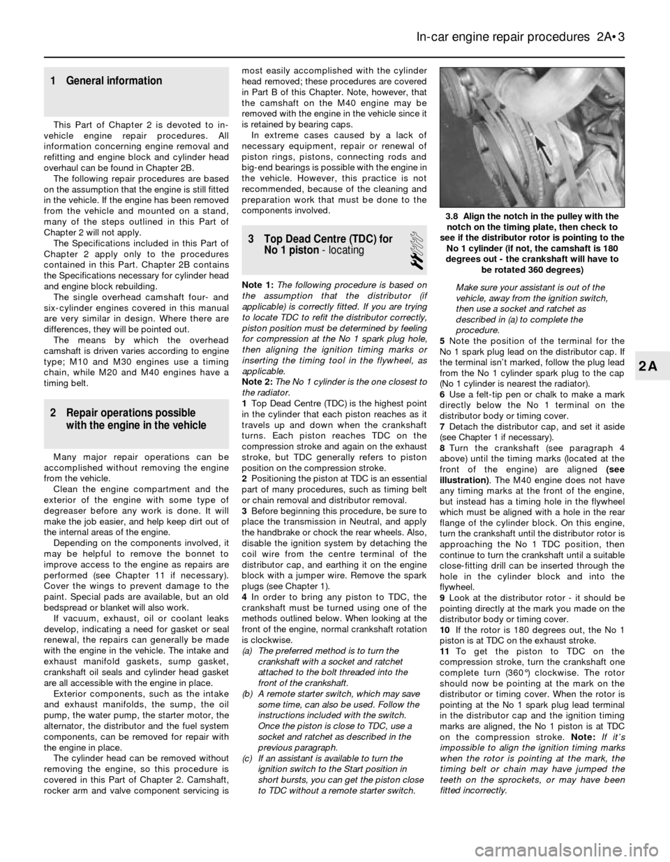
8Turn the crankshaft (see paragraph 4
above) until the timing marks (located at the
front of the engine) are aligned (see
illustration). The M40 engine does not have
any timing marks at the front of the engine,
but instead has a timing hole in the flywheel
which must be aligned with a hole in the rear
flange of the cylinder block. On this engine,
turn the crankshaft until the distributor rotor is
approaching the No 1 TDC position, then
continue to turn the crankshaft until a suitable
close-fitting drill can be inserted through the
hole in the cylinder block and into the
flywheel.
9Look at the distributor rotor - it should be
pointing directly at the mark you made on the
distributor body or timing cover.
10If the rotor is 180 degrees out, the No 1
piston is at TDC on the exhaust stroke.
11To get the piston to TDC on the
compression stroke, turn the crankshaft one
complete turn (360°) clockwise. The rotor
should now be pointing at the mark on the
distributor or timing cover. When the rotor is
pointing at the No 1 spark plug lead terminal
in the distributor cap and the ignition timing
marks are aligned, the No 1 piston is at TDC
on the compression stroke. Note:If it’s
impossible to align the ignition timing marks
when the rotor is pointing at the mark, the
timing belt or chain may have jumped the
teeth on the sprockets, or may have been
fitted incorrectly.
In-car engine repair procedures 2A•3
3.8 Align the notch in the pulley with the
notch on the timing plate, then check to
see if the distributor rotor is pointing to the
No 1 cylinder (if not, the camshaft is 180
degrees out - the crankshaft will have to
be rotated 360 degrees)
2A
Page 46 of 228
alignment mark on the camshaft sprocket and
rear timing cover to ensure correct refitting.
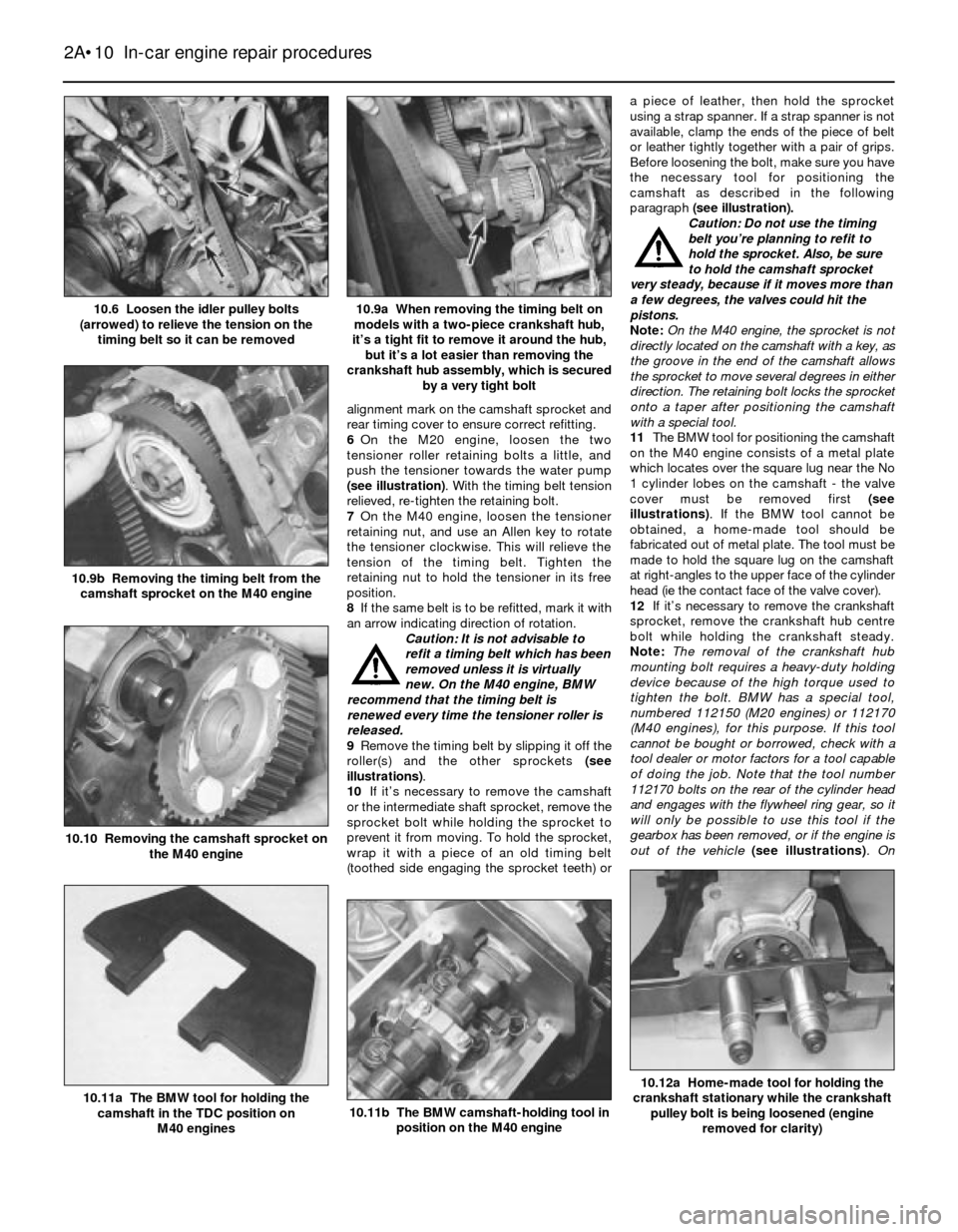
6On the M20 engine, loosen the two
tensioner roller retaining bolts a little, and
push the tensioner towards the water pump
(see illustration). With the timing belt tension
relieved, re-tighten the retaining bolt.
7On the M40 engine, loosen the tensioner
retaining nut, and use an Allen key to rotate
the tensioner clockwise. This will relieve the
tension of the timing belt. Tighten the
retaining nut to hold the tensioner in its free
position.
8If the same belt is to be refitted, mark it with
an arrow indicating direction of rotation.
Caution: It is not advisable to
refit a timing belt which has been
removed unless it is virtually
new. On the M40 engine, BMW
recommend that the timing belt is
renewed every time the tensioner roller is
released.
9Remove the timing belt by slipping it off the
roller(s) and the other sprockets (see
illustrations).
10If it’s necessary to remove the camshaft
or the intermediate shaft sprocket, remove the
sprocket bolt while holding the sprocket to
prevent it from moving. To hold the sprocket,
wrap it with a piece of an old timing belt
(toothed side engaging the sprocket teeth) ora piece of leather, then hold the sprocket
using a strap spanner. If a strap spanner is not
available, clamp the ends of the piece of belt
or leather tightly together with a pair of grips.
Before loosening the bolt, make sure you have
the necessary tool for positioning the
camshaft as described in the following
paragraph (see illustration).
Caution: Do not use the timing
belt you’re planning to refit to
hold the sprocket. Also, be sure
to hold the camshaft sprocket
very steady, because if it moves more than
a few degrees, the valves could hit the
pistons.
Note: On the M40 engine, the sprocket is not
directly located on the camshaft with a key, as
the groove in the end of the camshaft allows
the sprocket to move several degrees in either
direction. The retaining bolt locks the sprocket
onto a taper after positioning the camshaft
with a special tool.
11The BMW tool for positioning the camshaft
on the M40 engine consists of a metal plate
which locates over the square lug near the No
1 cylinder lobes on the camshaft - the valve
cover must be removed first (see
illustrations). If the BMW tool cannot be
obtained, a home-made tool should be
fabricated out of metal plate. The tool must be
made to hold the square lug on the camshaft
at right-angles to the upper face of the cylinder
head (ie the contact face of the valve cover).
12If it’s necessary to remove the crankshaft
sprocket, remove the crankshaft hub centre
bolt while holding the crankshaft steady.
Note:The removal of the crankshaft hub
mounting bolt requires a heavy-duty holding
device because of the high torque used to
tighten the bolt. BMW has a special tool,
numbered 112150 (M20 engines) or 112170
(M40 engines), for this purpose. If this tool
cannot be bought or borrowed, check with a
tool dealer or motor factors for a tool capable
of doing the job. Note that the tool number
112170 bolts on the rear of the cylinder head
and engages with the flywheel ring gear, so it
will only be possible to use this tool if the
gearbox has been removed, or if the engine is
out of the vehicle (see illustrations). On
2A•10 In-car engine repair procedures
10.12a Home-made tool for holding the
crankshaft stationary while the crankshaft
pulley bolt is being loosened (engine
removed for clarity)
10.11b The BMW camshaft-holding tool in
position on the M40 engine10.11a The BMW tool for holding the
camshaft in the TDC position on
M40 engines
10.10 Removing the camshaft sprocket on
the M40 engine
10.9b Removing the timing belt from the
camshaft sprocket on the M40 engine
10.9a When removing the timing belt on
models with a two-piece crankshaft hub,
it’s a tight fit to remove it around the hub,
but it’s a lot easier than removing the
crankshaft hub assembly, which is secured
by a very tight bolt10.6 Loosen the idler pulley bolts
(arrowed) to relieve the tension on the
timing belt so it can be removed
Page 51 of 228
13 Sump- removal and refitting
1
1Drain the engine oil (see Chapter 1).
2Raise the front of the vehicle and place it
securely on axle stands.
3Remove the splash shields from under the
engine.
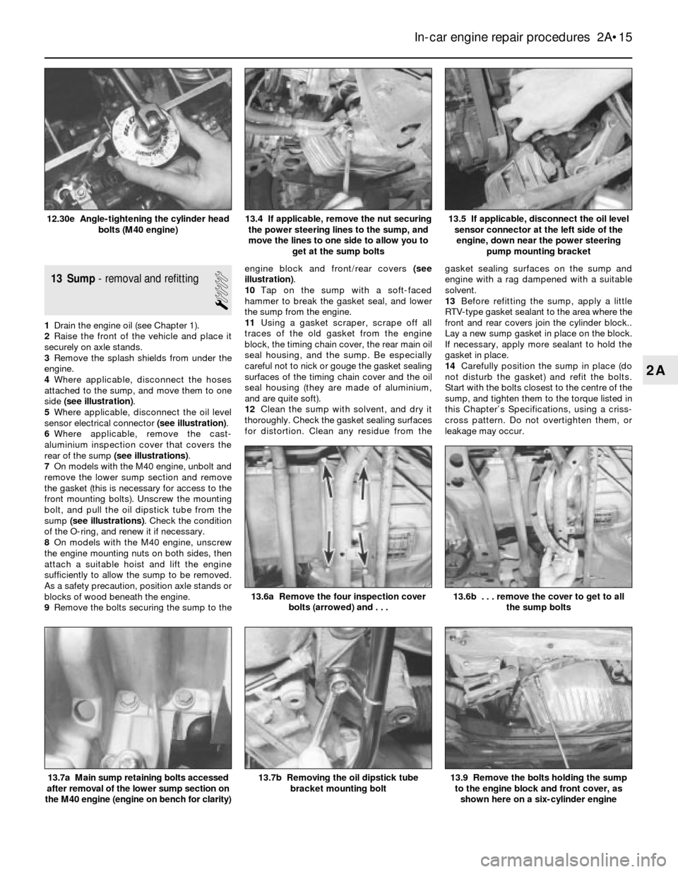
4Where applicable, disconnect the hoses
attached to the sump, and move them to one
side (see illustration).
5Where applicable, disconnect the oil level
sensor electrical connector (see illustration).
6Where applicable, remove the cast-
aluminium inspection cover that covers the
rear of the sump (see illustrations).
7On models with the M40 engine, unbolt and
remove the lower sump section and remove
the gasket (this is necessary for access to the
front mounting bolts). Unscrew the mounting
bolt, and pull the oil dipstick tube from the
sump (see illustrations). Check the condition
of the O-ring, and renew it if necessary.
8On models with the M40 engine, unscrew
the engine mounting nuts on both sides, then
attach a suitable hoist and lift the engine
sufficiently to allow the sump to be removed.
As a safety precaution, position axle stands or
blocks of wood beneath the engine.
9Remove the bolts securing the sump to theengine block and front/rear covers (see
illustration).
10Tap on the sump with a soft-faced
hammer to break the gasket seal, and lower
the sump from the engine.
11Using a gasket scraper, scrape off all
traces of the old gasket from the engine
block, the timing chain cover, the rear main oil
seal housing, and the sump. Be especially
careful not to nick or gouge the gasket sealing
surfaces of the timing chain cover and the oil
seal housing (they are made of aluminium,
and are quite soft).
12Clean the sump with solvent, and dry it
thoroughly. Check the gasket sealing surfaces
for distortion. Clean any residue from thegasket sealing surfaces on the sump and
engine with a rag dampened with a suitable
solvent.
13Before refitting the sump, apply a little
RTV-type gasket sealant to the area where the
front and rear covers join the cylinder block..
Lay a new sump gasket in place on the block.
If necessary, apply more sealant to hold the
gasket in place.
14Carefully position the sump in place (do
not disturb the gasket) and refit the bolts.
Start with the bolts closest to the centre of the
sump, and tighten them to the torque listed in
this Chapter’s Specifications, using a criss-
cross pattern. Do not overtighten them, or
leakage may occur.
In-car engine repair procedures 2A•15
13.5 If applicable, disconnect the oil level
sensor connector at the left side of the
engine, down near the power steering
pump mounting bracket13.4 If applicable, remove the nut securing
the power steering lines to the sump, and
move the lines to one side to allow you to
get at the sump bolts12.30e Angle-tightening the cylinder head
bolts (M40 engine)
13.9 Remove the bolts holding the sump
to the engine block and front cover, as
shown here on a six-cylinder engine13.7b Removing the oil dipstick tube
bracket mounting bolt
13.6b . . . remove the cover to get to all
the sump bolts13.6a Remove the four inspection cover
bolts (arrowed) and . . .
13.7a Main sump retaining bolts accessed
after removal of the lower sump section on
the M40 engine (engine on bench for clarity)
2A
Page 54 of 228
26Refit the cover plate and tighten the bolts
to the specified torque.
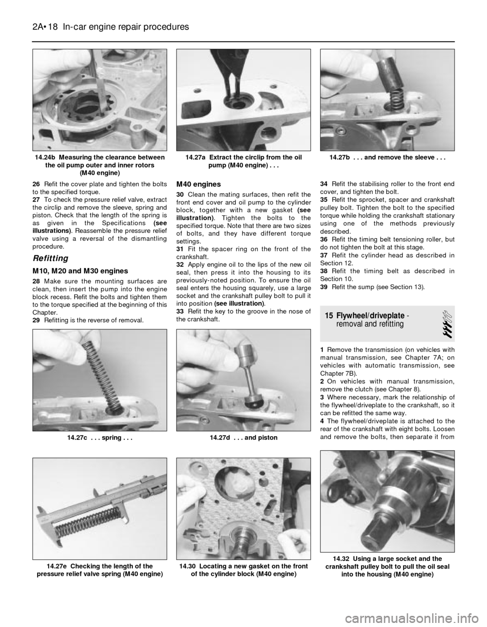
27To check the pressure relief valve, extract
the circlip and remove the sleeve, spring and
piston. Check that the length of the spring is
as given in the Specifications (see
illustrations). Reassemble the pressure relief
valve using a reversal of the dismantling
procedure.
Refitting
M10, M20 and M30 engines
28Make sure the mounting surfaces are
clean, then insert the pump into the engine
block recess. Refit the bolts and tighten them
to the torque specified at the beginning of this
Chapter.
29Refitting is the reverse of removal.
M40 engines
30Clean the mating surfaces, then refit the
front end cover and oil pump to the cylinder
block, together with a new gasket (see
illustration). Tighten the bolts to the
specified torque. Note that there are two sizes
of bolts, and they have different torque
settings.
31Fit the spacer ring on the front of the
crankshaft.
32Apply engine oil to the lips of the new oil
seal, then press it into the housing to its
previously-noted position. To ensure the oil
seal enters the housing squarely, use a large
socket and the crankshaft pulley bolt to pull it
into position (see illustration).
33Refit the key to the groove in the nose of
the crankshaft.34Refit the stabilising roller to the front end
cover, and tighten the bolt.
35Refit the sprocket, spacer and crankshaft
pulley bolt. Tighten the bolt to the specified
torque while holding the crankshaft stationary
using one of the methods previously
described.
36Refit the timing belt tensioning roller, but
do not tighten the bolt at this stage.
37Refit the cylinder head as described in
Section 12.
38Refit the timing belt as described in
Section 10.
39Refit the sump (see Section 13).
15 Flywheel/driveplate-
removal and refitting
3
1Remove the transmission (on vehicles with
manual transmission, see Chapter 7A; on
vehicles with automatic transmission, see
Chapter 7B).
2On vehicles with manual transmission,
remove the clutch (see Chapter 8).
3Where necessary, mark the relationship of
the flywheel/driveplate to the crankshaft, so it
can be refitted the same way.
4The flywheel/driveplate is attached to the
rear of the crankshaft with eight bolts. Loosen
and remove the bolts, then separate it from
2A•18 In-car engine repair procedures
14.32 Using a large socket and the
crankshaft pulley bolt to pull the oil seal
into the housing (M40 engine)14.30 Locating a new gasket on the front
of the cylinder block (M40 engine)14.27e Checking the length of the
pressure relief valve spring (M40 engine)
14.27d . . . and piston14.27c . . . spring . . .
14.27b . . . and remove the sleeve . . .14.27a Extract the circlip from the oil
pump (M40 engine) . . .14.24b Measuring the clearance between
the oil pump outer and inner rotors
(M40 engine)
Page 55 of 228
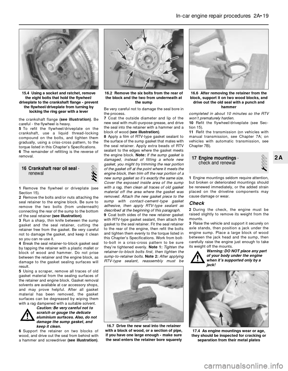
the crankshaft flange (see illustration). Be
careful - the flywheel is heavy.
5To refit the flywheel/driveplate on the
crankshaft, use a liquid thread-locking
compound on the bolts, and tighten them
gradually, using a criss-cross pattern, to the
torque listed in this Chapter’s Specifications.
6The remainder of refitting is the reverse of
removal.
16 Crankshaft rear oil seal-
renewal
3
1Remove the flywheel or driveplate (see
Section 15).
2Remove the bolts and/or nuts attaching the
seal retainer to the engine block. Be sure to
remove the two bolts (from underneath)
connecting the rear of the sump to the bottom
of the seal retainer (see illustration).
3Run a sharp, thin knife between the sump
gasket and the seal retainer, cutting the
retainer free from the gasket. Be very careful
not to damage the gasket, and keep it clean
so you can re-use it.
4Break the seal retainer-to-block gasket seal
by tapping the retainer with a plastic mallet or
block of wood and hammer. Do not prise
between the retainer and the engine block, as
damage to the gasket sealing surfaces will
result.
5Using a scraper, remove all traces of old
gasket material from the sealing surfaces of
the retainer and engine block. Gasket removal
solvents are available at car accessory shops,
and may prove helpful. After all gasket
material has been removed, the gasket
surfaces can be degreased by wiping them
with a rag dampened with a suitable solvent.
Caution: Be very careful not to
scratch or gouge the delicate
aluminium surfaces. Also, do not
damage the sump gasket, and
keep it clean.
6Support the retainer on two blocks of
wood, and drive out the seal from behind with
a hammer and screwdriver (see illustration).Be very careful not to damage the seal bore in
the process.
7Coat the outside diameter and lip of the
new seal with multi-purpose grease, and drive
the seal into the retainer with a hammer and a
block of wood (see illustration).
8Apply a film of RTV-type gasket sealant to
the surface of the sump gasket that mates with
the seal retainer. Apply extra beads of RTV
sealant to the edges where the gasket meets
the engine block. Note:If the sump gasket is
damaged, instead of fitting a whole new
gasket, you might try trimming the rear portion
of the gasket off at the point where it meets the
engine block, then trim off the rear portion of a
new sump gasket so it’s exactly the same size.
Cover the exposed inside area of the sump
with a rag, then clean all traces of old gasket
material off the area where the gasket was
removed. Attach the new gasket piece to the
sump with contact-cement-type gasket
adhesive, then apply RTV-type sealant as
described at the beginning of this paragraph.
9Coat both sides of the new retainer gasket
with RTV-type gasket sealant, then attach the
gasket to the seal retainer. Fit the seal retainer
to the rear of the engine, then refit the bolts
and tighten them evenly to the torque listed in
this Chapter’s Specifications. Work from bolt-
to-bolt in a criss-cross pattern to be sure
they’re tightened evenly.Note 1:Tighten the
retainer-to-block bolts first, then tighten the
sump-to-retainer bolts.Note 2:After applying
RTV-type sealant, reassembly must becompleted in about 10 minutes so the RTV
won’t prematurely harden.
10Refit the flywheel/driveplate (see Sec-
tion 15).
11Refit the transmission (on vehicles with
manual transmission, see Chapter 7A; on
vehicles with automatic transmission, see
Chapter 7B).
17 Engine mountings-
check and renewal
1
1Engine mountings seldom require attention,
but broken or deteriorated mountings should
be renewed immediately, or the added strain
placed on the driveline components may
cause damage or wear.
Check
2During the check, the engine must be
raised slightly to remove its weight from the
mounts.
3Raise the vehicle and support it securely on
axle stands, then position a jack under the
engine sump. Place a large block of wood
between the jack head and the sump, then
carefully raise the engine just enough to take
its weight off the mounts.
Warning: DO NOT place any part
of your body under the engine
when it’s supported only by a
jack!
In-car engine repair procedures 2A•19
16.6 After removing the retainer from the
block, support it on two wood blocks, and
drive out the old seal with a punch and
hammer16.2 Remove the six bolts from the rear of
the block and the two from underneath at
the sump15.4 Using a socket and ratchet, remove
the eight bolts that hold the flywheel/
driveplate to the crankshaft flange - prevent
the flywheel/driveplate from turning by
locking the ring gear with a lever
17.4 As engine mountings wear or age,
they should be inspected for cracking or
separation from their metal plates
16.7 Drive the new seal into the retainer
with a block of wood, or a section of pipe,
if you have one large enough - make sure
the seal enters the retainer bore squarely
2A
Page 57 of 228
2B
General
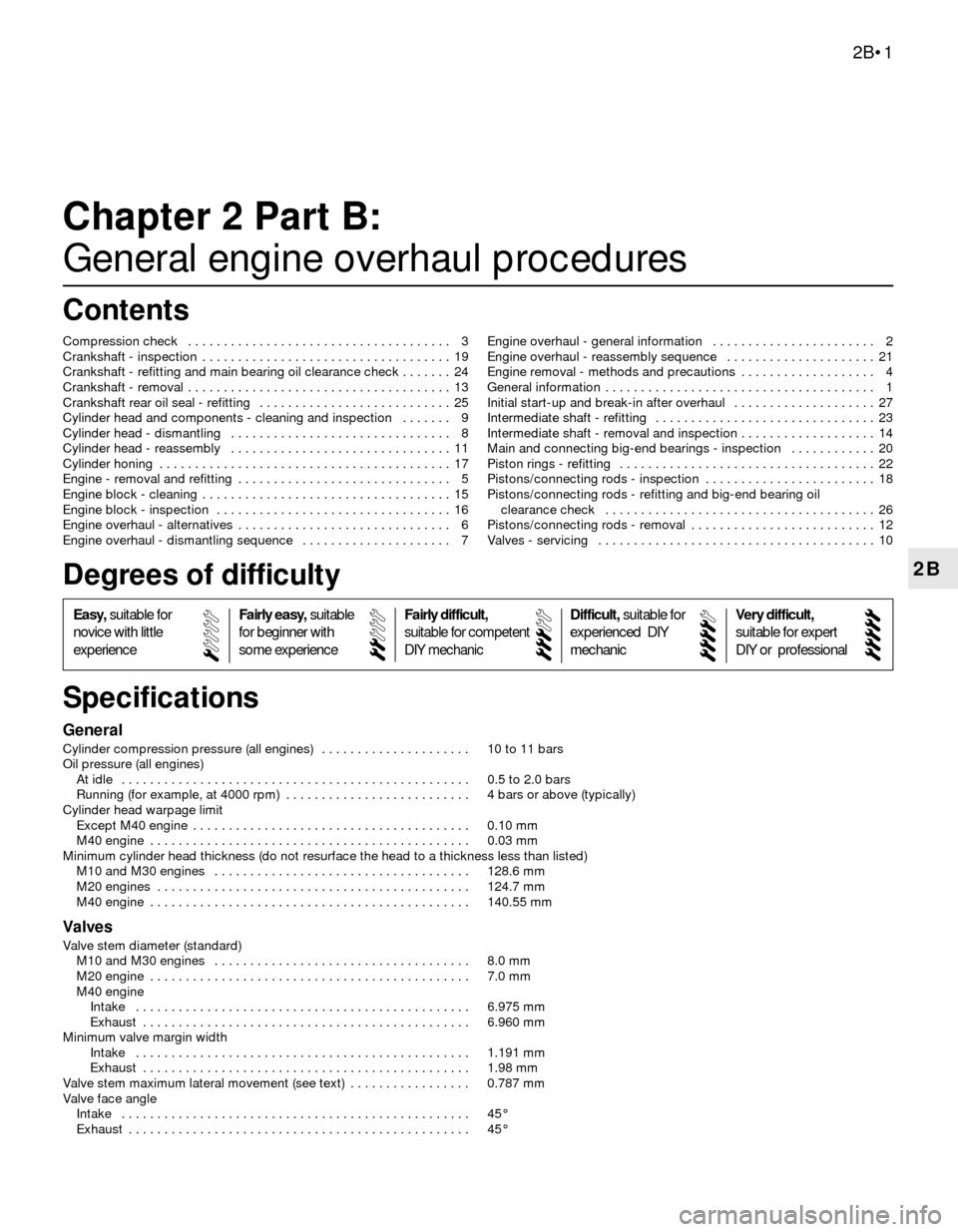
Cylinder compression pressure (all engines) . . . . . . . . . . . . . . . . . . . . . 10 to 11 bars
Oil pressure (all engines)
At idle . . . . . . . . . . . . . . . . . . . . . . . . . . . . . . . . . . . . . . . . . . . . . . . . . 0.5 to 2.0 bars
Running (for example, at 4000 rpm) . . . . . . . . . . . . . . . . . . . . . . . . . . 4 bars or above (typically)
Cylinder head warpage limit
Except M40 engine . . . . . . . . . . . . . . . . . . . . . . . . . . . . . . . . . . . . . . . 0.10 mm
M40 engine . . . . . . . . . . . . . . . . . . . . . . . . . . . . . . . . . . . . . . . . . . . . . 0.03 mm
Minimum cylinder head thickness (do not resurface the head to a thickness less than listed)
M10 and M30 engines . . . . . . . . . . . . . . . . . . . . . . . . . . . . . . . . . . . . 128.6 mm
M20 engines . . . . . . . . . . . . . . . . . . . . . . . . . . . . . . . . . . . . . . . . . . . . 124.7 mm
M40 engine . . . . . . . . . . . . . . . . . . . . . . . . . . . . . . . . . . . . . . . . . . . . . 140.55 mm
Valves
Valve stem diameter (standard)
M10 and M30 engines . . . . . . . . . . . . . . . . . . . . . . . . . . . . . . . . . . . . 8.0 mm
M20 engine . . . . . . . . . . . . . . . . . . . . . . . . . . . . . . . . . . . . . . . . . . . . . 7.0 mm
M40 engine
Intake . . . . . . . . . . . . . . . . . . . . . . . . . . . . . . . . . . . . . . . . . . . . . . . 6.975 mm
Exhaust . . . . . . . . . . . . . . . . . . . . . . . . . . . . . . . . . . . . . . . . . . . . . . 6.960 mm
Minimum valve margin width
Intake . . . . . . . . . . . . . . . . . . . . . . . . . . . . . . . . . . . . . . . . . . . . . . . 1.191 mm
Exhaust . . . . . . . . . . . . . . . . . . . . . . . . . . . . . . . . . . . . . . . . . . . . . . 1.98 mm
Valve stem maximum lateral movement (see text) . . . . . . . . . . . . . . . . . 0.787 mm
Valve face angle
Intake . . . . . . . . . . . . . . . . . . . . . . . . . . . . . . . . . . . . . . . . . . . . . . . . . 45°
Exhaust . . . . . . . . . . . . . . . . . . . . . . . . . . . . . . . . . . . . . . . . . . . . . . . . 45°
Chapter 2 Part B:
General engine overhaul procedures
Compression check . . . . . . . . . . . . . . . . . . . . . . . . . . . . . . . . . . . . . 3
Crankshaft - inspection . . . . . . . . . . . . . . . . . . . . . . . . . . . . . . . . . . . 19
Crankshaft - refitting and main bearing oil clearance check . . . . . . . 24
Crankshaft - removal . . . . . . . . . . . . . . . . . . . . . . . . . . . . . . . . . . . . . 13
Crankshaft rear oil seal - refitting . . . . . . . . . . . . . . . . . . . . . . . . . . . 25
Cylinder head and components - cleaning and inspection . . . . . . . 9
Cylinder head - dismantling . . . . . . . . . . . . . . . . . . . . . . . . . . . . . . . 8
Cylinder head - reassembly . . . . . . . . . . . . . . . . . . . . . . . . . . . . . . . 11
Cylinder honing . . . . . . . . . . . . . . . . . . . . . . . . . . . . . . . . . . . . . . . . . 17
Engine - removal and refitting . . . . . . . . . . . . . . . . . . . . . . . . . . . . . . 5
Engine block - cleaning . . . . . . . . . . . . . . . . . . . . . . . . . . . . . . . . . . . 15
Engine block - inspection . . . . . . . . . . . . . . . . . . . . . . . . . . . . . . . . . 16
Engine overhaul - alternatives . . . . . . . . . . . . . . . . . . . . . . . . . . . . . . 6
Engine overhaul - dismantling sequence . . . . . . . . . . . . . . . . . . . . . 7Engine overhaul - general information . . . . . . . . . . . . . . . . . . . . . . . 2
Engine overhaul - reassembly sequence . . . . . . . . . . . . . . . . . . . . . 21
Engine removal - methods and precautions . . . . . . . . . . . . . . . . . . . 4
General information . . . . . . . . . . . . . . . . . . . . . . . . . . . . . . . . . . . . . . 1
Initial start-up and break-in after overhaul . . . . . . . . . . . . . . . . . . . . 27
Intermediate shaft - refitting . . . . . . . . . . . . . . . . . . . . . . . . . . . . . . . 23
Intermediate shaft - removal and inspection . . . . . . . . . . . . . . . . . . . 14
Main and connecting big-end bearings - inspection . . . . . . . . . . . . 20
Piston rings - refitting . . . . . . . . . . . . . . . . . . . . . . . . . . . . . . . . . . . . 22
Pistons/connecting rods - inspection . . . . . . . . . . . . . . . . . . . . . . . . 18
Pistons/connecting rods - refitting and big-end bearing oil
clearance check . . . . . . . . . . . . . . . . . . . . . . . . . . . . . . . . . . . . . . 26
Pistons/connecting rods - removal . . . . . . . . . . . . . . . . . . . . . . . . . . 12
Valves - servicing . . . . . . . . . . . . . . . . . . . . . . . . . . . . . . . . . . . . . . . 10
2B•1
Easy,suitable for
novice with little
experienceFairly easy,suitable
for beginner with
some experienceFairly difficult,
suitable for competent
DIY mechanic
Difficult,suitable for
experienced DIY
mechanicVery difficult,
suitable for expert
DIY or professional
Degrees of difficulty
Specifications Contents
Page 60 of 228
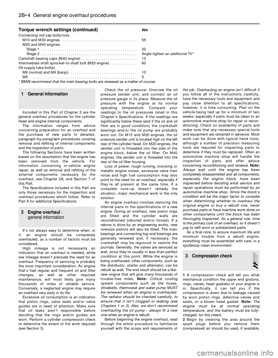
Torque wrench settings (continued)Nm
Connecting rod cap bolts/nuts
M10 and M30 engines . . . . . . . . . . . . . . . . . . . . . . . . . . . . . . . . . . . . 55
M20 and M40 engines
Stage 1 . . . . . . . . . . . . . . . . . . . . . . . . . . . . . . . . . . . . . . . . . . . . . . 20
Stage 2 . . . . . . . . . . . . . . . . . . . . . . . . . . . . . . . . . . . . . . . . . . . . . . Angle-tighten an additional 70°
Camshaft bearing caps (M40 engine) . . . . . . . . . . . . . . . . . . . . . . . . . . . 10
Intermediate shaft sprocket-to-shaft bolt (M20 engine) . . . . . . . . . . . . . 60
Oil supply tube bolt(s)
M6 (normal) and M8 (banjo) . . . . . . . . . . . . . . . . . . . . . . . . . . . . . . . . 10
M5 . . . . . . . . . . . . . . . . . . . . . . . . . . . . . . . . . . . . . . . . . . . . . . . . . . 5
* BMW recommend that the main bearing bolts are renewed as a matter of course.
2B•4 General engine overhaul procedures
1 General information
Included in this Part of Chapter 2 are the
general overhaul procedures for the cylinder
head and engine internal components.
The information ranges from advice
concerning preparation for an overhaul and
the purchase of new parts to detailed,
paragraph-by-paragraph procedures covering
removal and refitting of internal components
and the inspection of parts.
The following Sections have been written
based on the assumption that the engine has
been removed from the vehicle. For
information concerning in-vehicle engine
repair, as well as removal and refitting of the
external components necessary for the
overhaul, see Chapter 2A, and Section 7 of
this Part.
The Specifications included in this Part are
only those necessary for the inspection and
overhaul procedures which follow. Refer to
Part A for additional Specifications.
2 Engine overhaul-
general information
It’s not always easy to determine when, or
if, an engine should be completely
overhauled, as a number of factors must be
considered.
High mileage is not necessarily an
indication that an overhaul is needed, while
low mileage doesn’t preclude the need for an
overhaul. Frequency of servicing is probably
the most important consideration. An engine
that’s had regular and frequent oil and filter
changes, as well as other required
maintenance, will most likely give many
thousands of miles of reliable service.
Conversely, a neglected engine may require
an overhaul very early in its life.
Excessive oil consumption is an indication
that piston rings, valve seals and/or valve
guides are in need of attention. Make sure
that oil leaks aren’t responsible before
deciding that the rings and/or guides are
worn. Perform a cylinder compression check
to determine the extent of the work required
(see Section 3).Check the oil pressure: Unscrew the oil
pressure sender unit, and connect an oil
pressure gauge in its place. Measure the oil
pressure with the engine at its normal
operating temperature. Compare your
readings to the oil pressures listed in this
Chapter’s Specifications. If the readings are
significantly below these (and if the oil and oil
filter are in good condition), the crankshaft
bearings and/or the oil pump are probably
worn out. On M10 and M30 engines, the oil
pressure sender unit is located high on the left
rear of the cylinder head. On M20 engines, the
sender unit is threaded into the side of the
engine block, below the oil filter. On M40
engines, the sender unit is threaded into the
rear of the oil filter housing.
Loss of power, rough running, knocking or
metallic engine noises, excessive valve train
noise and high fuel consumption may also
point to the need for an overhaul, especially if
they’re all present at the same time. If a
complete tune-up doesn’t remedy the
situation, major mechanical work is the only
solution.
An engine overhaul involves restoring the
internal parts to the specifications of a new
engine. During an overhaul, new piston rings
are fitted and the cylinder walls are
reconditioned (rebored and/or honed). If a
rebore is done by an engineering works, new
oversize pistons will also be fitted. The main
bearings and connecting big-end bearings are
generally renewed and, if necessary, the
crankshaft may be reground to restore the
journals. Generally, the valves are serviced as
well, since they’re usually in less-than-perfect
condition at this point. While the engine is
being overhauled, other components, such as
the distributor, starter and alternator, can be
rebuilt as well. The end result should be a like-
new engine that will give many thousands of
trouble-free miles. Note: Critical cooling
system components such as the hoses,
drivebelts, thermostat and water pump MUST
be renewed when an engine is overhauled.
The radiator should be checked carefully, to
ensure that it isn’t clogged or leaking (see
Chapters 1 or 3). Also, we don’t recommend
overhauling the oil pump - always fit a new
one when an engine is rebuilt.
Before beginning the engine overhaul, read
through the entire procedure to familiarise
yourself with the scope and requirements ofthe job. Overhauling an engine isn’t difficult if
you follow all of the instructions carefully,
have the necessary tools and equipment and
pay close attention to all specifications;
however, it is time consuming. Plan on the
vehicle being tied up for a minimum of two
weeks, especially if parts must be taken to an
automotive machine shop for repair or recon-
ditioning. Check on availability of parts and
make sure that any necessary special tools
and equipment are obtained in advance. Most
work can be done with typical hand tools,
although a number of precision measuring
tools are required for inspecting parts to
determine if they must be replaced. Often an
automotive machine shop will handle the
inspection of parts and offer advice
concerning reconditioning and renewal. Note:
Always wait until the engine has been
completely disassembled and all components,
especially the engine block, have been
inspected before deciding what service and
repair operations must be performed by an
automotive machine shop. Since the block’s
condition will be the major factor to consider
when determining whether to overhaul the
original engine or buy a rebuilt one, never
purchase parts or have machine work done on
other components until the block has been
thoroughly inspected. As a general rule, time
is the primary cost of an overhaul, so it doesn’t
pay to refit worn or substandard parts.
As a final note, to ensure maximum life and
minimum trouble from a rebuilt engine,
everything must be assembled with care, in a
spotlessly-clean environment.
3 Compression check
2
1A compression check will tell you what
mechanical condition the upper end (pistons,
rings, valves, head gaskets) of your engine is
in. Specifically, it can tell you if the
compression is down due to leakage caused
by worn piston rings, defective valves and
seats, or a blown head gasket. Note:The
engine must be at normal operating
temperature, and the battery must be fully-
charged, for this check.
2Begin by cleaning the area around the
spark plugs before you remove them
(compressed air should be used, if available,