Rear BMW 3 SERIES 1989 E30 Owner's Manual
[x] Cancel search | Manufacturer: BMW, Model Year: 1989, Model line: 3 SERIES, Model: BMW 3 SERIES 1989 E30Pages: 228, PDF Size: 7.04 MB
Page 62 of 228
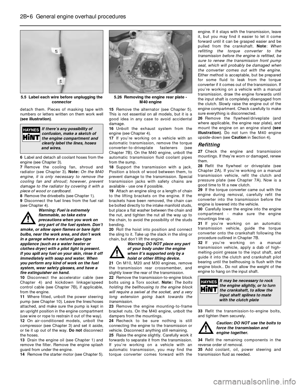
detach them. Pieces of masking tape with
numbers or letters written on them work well
(see illustration).
6Label and detach all coolant hoses from the
engine (see Chapter 3).
7Remove the cooling fan, shroud and
radiator (see Chapter 3). Note:On the M40
engine, it is only necessary to remove the
cooling fan and shroud; however, prevent
damage to the radiator by covering it with a
piece of wood or cardboard.
8Remove the drivebelts (see Chapter 1).
9Disconnect the fuel lines from the fuel rail
(see Chapter 4).
Warning: Fuel is extremely
flammable, so take extra
precautions when you work on
any part of the fuel system. Don’t
smoke, or allow open flames or bare light
bulbs, near the work area, and don’t work
in a garage where a natural gas-type
appliance (such as a water heater or
clothes dryer) with a pilot light is present.
If you spill any fuel on your skin, rinse it off
immediately with soap and water. When
you perform any kind of work on the fuel
system, wear safety glasses, and have a
fire extinguisher on hand.
10Disconnect the accelerator cable (see
Chapter 4) and kickdown linkage/speed
control cable (see Chapter 7B), if applicable,
from the engine.
11Where fitted, unbolt the power steering
pump (see Chapter 10). Leave the lines/hoses
attached, and make sure the pump is kept in
an upright position in the engine compartment
(use wire or rope to restrain it out of the way).
12On air-conditioned models, unbolt the
compressor (see Chapter 3) and set it aside,
or tie it up out of the way. Do not disconnect
the hoses.
13Drain the engine oil (see Chapter 1) and
remove the filter. Remove the engine splash
guard from under the engine.
14Remove the starter motor (see Chapter 5).15Remove the alternator (see Chapter 5).
This is not essential on all models, but it is a
good idea in any case to avoid accidental
damage.
16Unbolt the exhaust system from the
engine (see Chapter 4).
17If you’re working on a vehicle with an
automatic transmission, remove the torque
converter-to-driveplate fasteners (see
Chapter 7B). On the M40 engine, unbolt the
automatic transmission fluid coolant pipes
from the sump.
18Support the transmission with a jack.
Position a block of wood between them, to
prevent damage to the transmission. Special
transmission jacks with safety chains are
available - use one if possible.
19Attach an engine sling or a length of chain
to the lifting brackets on the engine. If the
brackets have been removed, the chain can
be bolted directly to the intake manifold studs,
but place a flat washer between the chain and
the nut, and tighten the nut all the way up to
the chain, to avoid the possibility of the studs
bending.
20Roll the hoist into position and connect
the sling to it. Take up the slack in the sling or
chain, but don’t lift the engine.
Warning: DO NOT place any part
of your body under the engine
when it’s supported only by a
hoist or other lifting device.
21On M10, M20 and M30 engines, remove
the transmission rear crossmember, and
slightly lower the rear of the transmission.
22Remove the transmission-to-engine block
bolts using a Torx socket. Note:The bolts
holding the bellhousing to the engine block
will require a swivel at the socket, and a very
long extension going back towards the
transmission.
23Remove the engine mounting-to-frame
bracket nuts. On the M40 engine, unbolt the
dampers from the mountings.
24Recheck to be sure nothing is still
connecting the engine to the transmission or
vehicle. Disconnect anything still remaining.
25Raise the engine slightly. Carefully work it
forwards to separate it from the transmission.
If you’re working on a vehicle with an
automatic transmission, you may find the
torque converter comes forward with theengine. If it stays with the transmission, leave
it, but you may find it easier to let it come
forward until it can be grasped easier and be
pulled from the crankshaft. Note:When
refitting the torque converter to the
transmission before the engine is refitted, be
sure to renew the transmission front pump
seal, which will probably be damaged when
the converter comes out with the engine.
Either method is acceptable, but be prepared
for some fluid to leak from the torque
converter if it comes out of the transmission. If
you’re working on a vehicle with a manual
transmission, draw the engine forwards until
the input shaft is completely disengaged from
the clutch. Slowly raise the engine out of the
engine compartment. Check carefully to make
sure everything is disconnected.
26Remove the flywheel/driveplate (and
where applicable, the engine rear plate), and
mount the engine on an engine stand (see
illustration). Do not turn the M40 engine
upside-down (see Cautionin Section 4).
Refitting
27Check the engine and transmission
mountings. If they’re worn or damaged, renew
them.
28Refit the flywheel or driveplate (see
Chapter 2A). If you’re working on a manual
transmission vehicle, refit the clutch and
pressure plate (see Chapter 7A). Now is a
good time to fit a new clutch.
29If the torque converter came out with the
engine during removal, carefully refit the
converter into the transmission before the
engine is lowered into the vehicle.
30Carefully lower the engine into the engine
compartment - make sure the engine
mountings line up.
31If you’re working on an automatic
transmission vehicle, guide the torque
converter onto the crankshaft following the
procedure outlined in Chapter 7B.
32If you’re working on a manual
transmission vehicle, apply a dab of high-
melting-point grease to the input shaft, and
guide it into the clutch and crankshaft pilot
bearing until the bellhousing is flush with the
engine block.. Do not allow the weight of the
engine to hang on the input shaft.
33Refit the transmission-to-engine bolts,
and tighten them securely.
Caution: DO NOT use the bolts to
force the transmission and
engine together.
34Refit the remaining components in the
reverse order of removal.
35Add coolant, oil, power steering and
transmission fluid as needed.
2B•6 General engine overhaul procedures
5.26 Removing the engine rear plate -
M40 engine5.5 Label each wire before unplugging the
connector
If there’s any possibility of
confusion, make a sketch of
the engine compartment and
clearly label the lines, hoses
and wires.
It may be necessary to rock
the engine slightly, or to turn
the crankshaft, to allow the
input shaft splines to mate
with the clutch plate
Page 63 of 228
36Run the engine and check for leaks and
proper operation of all accessories, then refit
the bonnet and test drive the vehicle.
37Where necessary, have the air
conditioning system recharged and leak-
tested.
6 Engine overhaul- alternatives
The do-it-yourselfer is faced with a number
of options when performing an engine
overhaul. The decision to renew the engine
block, piston/connecting rod assemblies and
crankshaft depends on a number of factors,
with the number one consideration being the
condition of the block. Other considerations
are cost, access to machine shop facilities,
parts availability, time required to complete
the project, and the extent of prior mechanical
experience on the part of the do-it-yourselfer.
Some of the alternatives include:
Individual parts - If the inspection
procedures reveal that the engine block and
most engine components are in re-usable
condition, purchasing individual parts may be
the most economical alternative. The block,
crankshaft and piston/connecting rod
assemblies should all be inspected carefully.
Even if the block shows little wear, the
cylinder bores should be surface-honed.
Crankshaft kit- A crankshaft kit (where
available) consists of a reground crankshaft
with matched undersize new main and
connecting big-end bearings. Sometimes,
reconditioned connecting rods and new
pistons and rings are included with the kit
(such a kit is sometimes called an “engine
kit”). If the block is in good condition, but the
crankshaft journals are scored or worn, a
crankshaft kit and other individual parts may
be the most economical alternative.
Short block- A short block consists of an
engine block with a crankshaft and
piston/connecting rod assemblies already
fitted. New bearings are fitted, and all
clearances will be correct. The existing
camshaft, valve train components, cylinder
head and external parts can be bolted to the
short block with little or no machine shop
work necessary.
Full block - A “full” or “complete” block
consists of a short block plus an oil pump,
sump, cylinder head, valve cover, camshaft
and valve train components, timing sprockets
and chain (or belt) and timing cover. All
components are fitted with new bearings,
seals and gaskets used throughout. The
refitting of manifolds and external parts is all
that’s necessary.
Give careful thought to which alternative is
best for you, and discuss the situation with
local machine shops, parts dealers and
experienced rebuilders before ordering or
purchasing new parts.
7 Engine overhaul-
dismantling sequence
1It’s much easier to dismantle and work on
the engine if it’s mounted on a portable
engine stand. A stand can often be hired quite
cheaply from a tool hire shop. Before the
engine is mounted on a stand, the
flywheel/driveplate should be removed from
the engine.
2If a stand isn’t available, it’s possible to
dismantle the engine with it blocked up on the
floor. Be extra-careful not to tip or drop the
engine when working without a stand.
3If you’re going to obtain a rebuilt engine, all
the external components listed below must
come off first, to be transferred to the new
engine if applicable. This is also the case if
you’re doing a complete engine overhaul
yourself. Note:When removing the external
components from the engine, pay close
attention to details that may be helpful or
important during refitting. Note the fitted
position of gaskets, seals, spacers, pins,
brackets, washers, bolts and other small items.
Alternator and brackets
Emissions control components
Distributor, HT leads and spark plugs
Thermostat and housing cover
Water pump
Fuel injection/carburettor and fuel system
components
Intake and exhaust manifolds
Oil filter and oil pressure sending unit
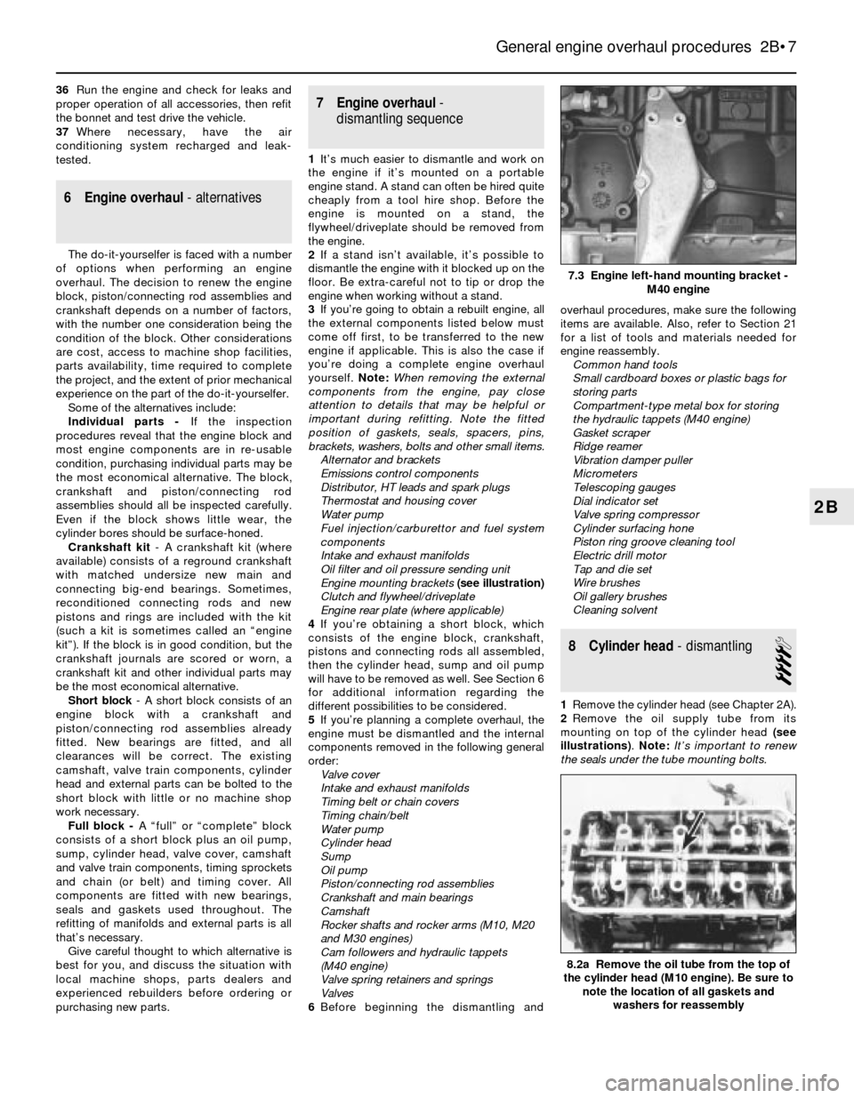
Engine mounting brackets (see illustration)
Clutch and flywheel/driveplate
Engine rear plate (where applicable)
4If you’re obtaining a short block, which
consists of the engine block, crankshaft,
pistons and connecting rods all assembled,
then the cylinder head, sump and oil pump
will have to be removed as well. See Section 6
for additional information regarding the
different possibilities to be considered.
5If you’re planning a complete overhaul, the
engine must be dismantled and the internal
components removed in the following general
order:
Valve cover
Intake and exhaust manifolds
Timing belt or chain covers
Timing chain/belt
Water pump
Cylinder head
Sump
Oil pump
Piston/connecting rod assemblies
Crankshaft and main bearings
Camshaft
Rocker shafts and rocker arms (M10, M20
and M30 engines)
Cam followers and hydraulic tappets
(M40 engine)
Valve spring retainers and springs
Valves
6Before beginning the dismantling andoverhaul procedures, make sure the following
items are available. Also, refer to Section 21
for a list of tools and materials needed for
engine reassembly.
Common hand tools
Small cardboard boxes or plastic bags for
storing parts
Compartment-type metal box for storing
the hydraulic tappets (M40 engine)
Gasket scraper
Ridge reamer
Vibration damper puller
Micrometers
Telescoping gauges
Dial indicator set
Valve spring compressor
Cylinder surfacing hone
Piston ring groove cleaning tool
Electric drill motor
Tap and die set
Wire brushes
Oil gallery brushes
Cleaning solvent
8 Cylinder head- dismantling
4
1Remove the cylinder head (see Chapter 2A).
2Remove the oil supply tube from its
mounting on top of the cylinder head (see
illustrations). Note:It’s important to renew
the seals under the tube mounting bolts.
General engine overhaul procedures 2B•7
7.3 Engine left-hand mounting bracket -
M40 engine
8.2a Remove the oil tube from the top of
the cylinder head (M10 engine). Be sure to
note the location of all gaskets and
washers for reassembly
2B
Page 64 of 228
M10, M20 and M30 engines
3Adjust all valves to their maximum clearance
by rotating the eccentric on the valve end of
the rocker arm towards the centre of the head
(see Chapter 1, if necessary).
4Before removing the thrustplate, measure
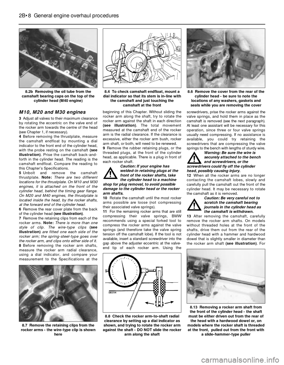
the camshaft endfloat by mounting a dial
indicator to the front end of the cylinder head,
with the probe resting on the camshaft (see
illustration). Prise the camshaft back-and-
forth in the cylinder head. The reading is the
camshaft endfloat. Compare the reading to
this Chapter’s Specifications.
5Unbolt and remove the camshaft
thrustplate. Note:There are two different
locations for the thrustplate. On M10 and M30
engines, it is attached on the front of the
cylinder head, behind the timing gear flange.
On M20 and M40 engines, the thrustplate is
located inside the head, by the rocker shafts,
at the forward end of the cylinder head.
6Remove the rear cover plate from the back
of the cylinder head (see illustration).
7Remove the retaining clips from each of the
rocker arms. Note:There is more than one
style of clip. The wire-type clips (see
illustration)are fitted one each side of the
rocker arm; the spring-steel-type goes over
the rocker arm, and clips onto either side of it.
8Before removing the rocker arm shafts,
measure the rocker arm radial clearance,
using a dial indicator, and compare your
measurement to the Specifications at thebeginning of this Chapter. Without sliding the
rocker arm along the shaft, try to rotate the
rocker arm against the shaft in each direction
(see illustration). The total movement
measured at the camshaft end of the rocker
arm is the radial clearance. If the clearance is
excessive, either the rocker arm bush, rocker
arm shaft, or both, will need to be renewed.
9Remove the rubber retaining plugs, or the
threaded plugs, at the front of the cylinder
head, as applicable. There is a plug in front of
each rocker shaft.
Caution: If your engine has
welded-in retaining plugs at the
front of the rocker shafts, take
the cylinder head to a machine
shop for plug removal, to avoid possible
damage to the cylinder head or the rocker
arm shafts.
10Rotate the camshaft until the most rocker
arms possible are loose (not compressing
their associated valve springs).
11For the remaining rocker arms that are still
compressing their valve springs, BMW
recommends using a special forked tool to
compress the rocker arms against the valve
springs (and therefore take the valve spring
tension off the camshaft lobe). If the tool is not
available, insert a standard screwdriver into the
gap above the adjuster eccentric at the valve-
end tip of each rocker arm. Using thescrewdrivers, prise the rocker arms against the
valve springs, and hold them in place as the
camshaft is removed (see the next paragraph).
At least one assistant will be necessary for this
operation, since three or four valve springs
usually need compressing. If no assistance is
available, you could try retaining the
screwdrivers that are compressing the valve
springs to the bench with lengths of sturdy wire.
Warning: Be sure the wire is
securely attached to the bench
and screwdrivers, or the
screwdrivers could fly off the cylinder
head, possibly causing injury.
12When all the rocker arms are no longer
contacting the camshaft lobes, slowly and
carefully pull the camshaft out the front of the
cylinder head. It may be necessary to rotate
the camshaft as it is removed.
Caution: Be very careful not to
scratch the camshaft bearing
journals in the cylinder head as
the camshaft is withdrawn.
13After removing the camshaft, carefully
remove the rocker arm shafts. On models
without threaded holes at the front of the
shafts, drive them out from the rear of the
cylinder head with a hammer and hardwood
dowel that is slightly smaller in diameter than
the rocker arm shaft (see illustration). For
2B•8 General engine overhaul procedures
8.13 Removing a rocker arm shaft from
the front of the cylinder head - the shaft
must be either driven out from the rear of
the head with a hardwood dowel or, on
models where the rocker shaft is threaded
at the front, pulled out from the front with
a slide-hammer-type puller
8.8 Check the rocker arm-to-shaft radial
clearance by setting up a dial indicator as
shown, and trying to rotate the rocker arm
against the shaft - DO NOT slide the rocker
arm along the shaft
8.7 Remove the retaining clips from the
rocker arms - the wire-type clip is shown
here
8.6 Remove the cover from the rear of the
cylinder head - be sure to note the
locations of any washers, gaskets and
seals while you are removing the cover8.4 To check camshaft endfloat, mount a
dial indicator so that its stem is in-line with
the camshaft and just touching the
camshaft at the front8.2b Removing the oil tube from the
camshaft bearing caps on the top of the
cylinder head (M40 engine)
Page 69 of 228
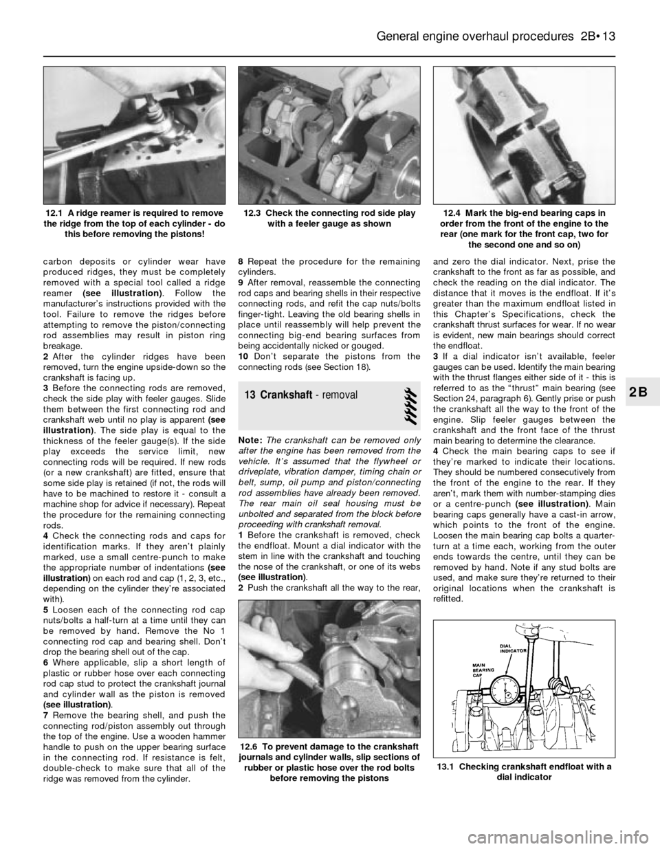
carbon deposits or cylinder wear have
produced ridges, they must be completely
removed with a special tool called a ridge
reamer (see illustration). Follow the
manufacturer’s instructions provided with the
tool. Failure to remove the ridges before
attempting to remove the piston/connecting
rod assemblies may result in piston ring
breakage.
2After the cylinder ridges have been
removed, turn the engine upside-down so the
crankshaft is facing up.
3Before the connecting rods are removed,
check the side play with feeler gauges. Slide
them between the first connecting rod and
crankshaft web until no play is apparent (see
illustration). The side play is equal to the
thickness of the feeler gauge(s). If the side
play exceeds the service limit, new
connecting rods will be required. If new rods
(or a new crankshaft) are fitted, ensure that
some side play is retained (if not, the rods will
have to be machined to restore it - consult a
machine shop for advice if necessary). Repeat
the procedure for the remaining connecting
rods.
4Check the connecting rods and caps for
identification marks. If they aren’t plainly
marked, use a small centre-punch to make
the appropriate number of indentations (see
illustration)on each rod and cap (1, 2, 3, etc.,
depending on the cylinder they’re associated
with).
5Loosen each of the connecting rod cap
nuts/bolts a half-turn at a time until they can
be removed by hand. Remove the No 1
connecting rod cap and bearing shell. Don’t
drop the bearing shell out of the cap.
6Where applicable, slip a short length of
plastic or rubber hose over each connecting
rod cap stud to protect the crankshaft journal
and cylinder wall as the piston is removed
(see illustration).
7Remove the bearing shell, and push the
connecting rod/piston assembly out through
the top of the engine. Use a wooden hammer
handle to push on the upper bearing surface
in the connecting rod. If resistance is felt,
double-check to make sure that all of the
ridge was removed from the cylinder.8Repeat the procedure for the remaining
cylinders.
9After removal, reassemble the connecting
rod caps and bearing shells in their respective
connecting rods, and refit the cap nuts/bolts
finger-tight. Leaving the old bearing shells in
place until reassembly will help prevent the
connecting big-end bearing surfaces from
being accidentally nicked or gouged.
10Don’t separate the pistons from the
connecting rods (see Section 18).
13 Crankshaft- removal
5
Note: The crankshaft can be removed only
after the engine has been removed from the
vehicle. It’s assumed that the flywheel or
driveplate, vibration damper, timing chain or
belt, sump, oil pump and piston/connecting
rod assemblies have already been removed.
The rear main oil seal housing must be
unbolted and separated from the block before
proceeding with crankshaft removal.
1Before the crankshaft is removed, check
the endfloat. Mount a dial indicator with the
stem in line with the crankshaft and touching
the nose of the crankshaft, or one of its webs
(see illustration).
2Push the crankshaft all the way to the rear,and zero the dial indicator. Next, prise the
crankshaft to the front as far as possible, and
check the reading on the dial indicator. The
distance that it moves is the endfloat. If it’s
greater than the maximum endfloat listed in
this Chapter’s Specifications, check the
crankshaft thrust surfaces for wear. If no wear
is evident, new main bearings should correct
the endfloat.
3If a dial indicator isn’t available, feeler
gauges can be used. Identify the main bearing
with the thrust flanges either side of it - this is
referred to as the “thrust” main bearing (see
Section 24, paragraph 6). Gently prise or push
the crankshaft all the way to the front of the
engine. Slip feeler gauges between the
crankshaft and the front face of the thrust
main bearing to determine the clearance.
4Check the main bearing caps to see if
they’re marked to indicate their locations.
They should be numbered consecutively from
the front of the engine to the rear. If they
aren’t, mark them with number-stamping dies
or a centre-punch (see illustration). Main
bearing caps generally have a cast-in arrow,
which points to the front of the engine.
Loosen the main bearing cap bolts a quarter-
turn at a time each, working from the outer
ends towards the centre, until they can be
removed by hand. Note if any stud bolts are
used, and make sure they’re returned to their
original locations when the crankshaft is
refitted.
General engine overhaul procedures 2B•13
12.4 Mark the big-end bearing caps in
order from the front of the engine to the
rear (one mark for the front cap, two for
the second one and so on)12.3 Check the connecting rod side play
with a feeler gauge as shown12.1 A ridge reamer is required to remove
the ridge from the top of each cylinder - do
this before removing the pistons!
13.1 Checking crankshaft endfloat with a
dial indicator
12.6 To prevent damage to the crankshaft
journals and cylinder walls, slip sections of
rubber or plastic hose over the rod bolts
before removing the pistons
2B
Page 74 of 228
3When examining the bearings, remove
them from the engine block, the main bearing
caps, the connecting rods and the rod caps,
and lay them out on a clean surface in the
same general position as their location in the
engine. This will enable you to match any
bearing problems with the corresponding
crankshaft journal.
4Dirt and other foreign particles get into the
engine in a variety of ways. It may be left in
the engine during assembly, or it may pass
through filters or the crankcase ventilation
(PCV) system. It may get into the oil, and from
there into the bearings. Metal chips from
machining operations and normal engine wear
are often present. Abrasives are sometimes
left in engine components after recondi-
tioning, especially when parts are not
thoroughly cleaned using the proper cleaning
methods. Whatever the source, these foreign
objects often end up embedded in the soft
bearing material, and are easily recognised.
Large particles will not embed in the bearing,
and will score or gouge the bearing and
journal. The best prevention for this cause of
bearing failure is to clean all parts thoroughly,
and to keep everything spotlessly-clean
during engine assembly. Frequent and regular
engine oil and filter changes are also
recommended.
5Lack of lubrication (or lubrication
breakdown) has a number of interrelated
causes. Excessive heat (which thins the oil),
overloading (which squeezes the oil from the
bearing face) and oil “leakage” or “throw off”
(from excessive bearing clearances, worn oil
pump, or high engine speeds) all contribute to
lubrication breakdown. Blocked oil passages,
which usually are the result of misaligned oil
holes in a bearing shell, will also oil-starve a
bearing and destroy it. When lack of
lubrication is the cause of bearing failure, the
bearing material is wiped or extruded from the
steel backing of the bearing. Temperatures
may increase to the point where the steel
backing turns blue from overheating.
6Driving habits can have a definite effect on
bearing life. Full-throttle, low-speed operation
(labouring the engine) puts very high loads onbearings, which tends to squeeze out the oil
film. These loads cause the bearings to flex,
which produces fine cracks in the bearing
face (fatigue failure). Eventually, the bearing
material will loosen in places, and tear away
from the steel backing. Short-trip driving
leads to corrosion of bearings, because
insufficient engine heat is produced to drive
off the condensation and corrosive gases.
These products collect in the engine oil,
forming acid and sludge. As the oil is carried
to the engine bearings, the acid attacks and
corrodes the bearing material.
7Incorrect bearing refitting during engine
assembly will lead to bearing failure as well.
Tight-fitting bearings leave insufficient bearing
oil clearance, and will result in oil starvation.
Dirt or foreign particles trapped behind a
bearing shell result in high spots on the
bearing, which will lead to failure.
21 Engine overhaul-
reassembly sequence
1Before beginning engine reassembly, make
sure you have all the necessary new parts,
gaskets and seals, as well as the following
items on hand:
Common hand tools
A torque wrench
Piston ring refitting tool
Piston ring compressor
Vibration damper refitting tool
Short lengths of rubber or plastic hose to fit
over connecting rod bolts (where
applicable)
Plastigage
Feeler gauges
A fine-tooth file
New engine oil
Engine assembly oil or molybdenum
disulphide (“moly”) grease
Gasket sealant
Thread-locking compound
2In order to save time and avoid problems,
engine reassembly should be done in the
following general order:Piston rings
Crankshaft and main bearings
Piston/connecting rod assemblies
Oil pump
Sump
Cylinder head assembly
Timing belt or chain and tensioner
assemblies
Water pump
Timing belt or chain covers
Intake and exhaust manifolds
Valve cover
Engine rear plate
Flywheel/driveplate
22 Piston rings- refitting
2
1Before fitting the new piston rings, the ring
end gaps must be checked. It’s assumed that
the piston ring side clearance has been
checked and verified (see Section 18).
2Lay out the piston/connecting rod
assemblies and the new ring sets, so that the
ring sets will be matched with the same piston
and cylinder during the end gap measurement
and engine assembly.
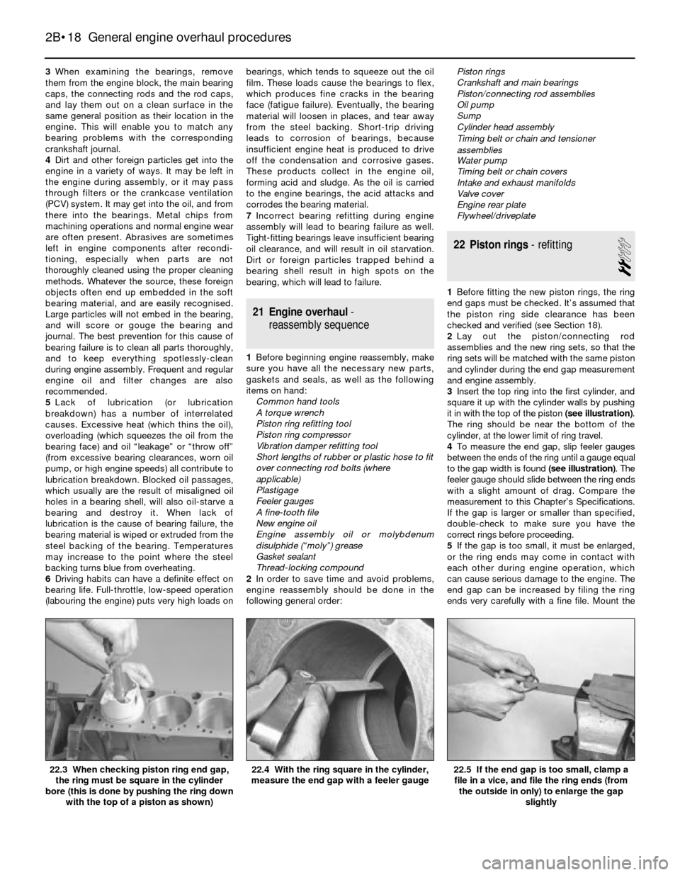
3Insert the top ring into the first cylinder, and
square it up with the cylinder walls by pushing
it in with the top of the piston (see illustration).
The ring should be near the bottom of the
cylinder, at the lower limit of ring travel.
4To measure the end gap, slip feeler gauges
between the ends of the ring until a gauge equal
to the gap width is found(see illustration). The
feeler gauge should slide between the ring ends
with a slight amount of drag. Compare the
measurement to this Chapter’s Specifications.
If the gap is larger or smaller than specified,
double-check to make sure you have the
correct rings before proceeding.
5If the gap is too small, it must be enlarged,
or the ring ends may come in contact with
each other during engine operation, which
can cause serious damage to the engine. The
end gap can be increased by filing the ring
ends very carefully with a fine file. Mount the
2B•18 General engine overhaul procedures
22.5 If the end gap is too small, clamp a
file in a vice, and file the ring ends (from
the outside in only) to enlarge the gap
slightly22.4 With the ring square in the cylinder,
measure the end gap with a feeler gauge22.3 When checking piston ring end gap,
the ring must be square in the cylinder
bore (this is done by pushing the ring down
with the top of a piston as shown)
Page 76 of 228
positions (don’t mix them up) with the arrows
pointing towards the front of the engine. Don’t
disturb the Plastigage.
13Starting with the centre main bearing and
working out toward the ends, progressively
tighten the main bearing cap bolts to the
torque listed in this Chapter’s Specifications.
On M10, M20 and M30 engines, tighten the
bolts in three stages. On the M40 engine,
tighten all the bolts initially to the Stage 1
torque, then angle-tighten them by the angle
given in the Specifications. Carry out the
angle-tightening on each bolt in one
controlled movement. Don’t rotate the
crankshaft at any time during the tightening
operation.
14Remove the bolts and carefully lift off the
main bearing caps. Keep them in order. Don’t
disturb the Plastigage or rotate the
crankshaft. If any of the main bearing caps are
difficult to remove, tap them gently from side-
to-side with a soft-face hammer to loosen
them.
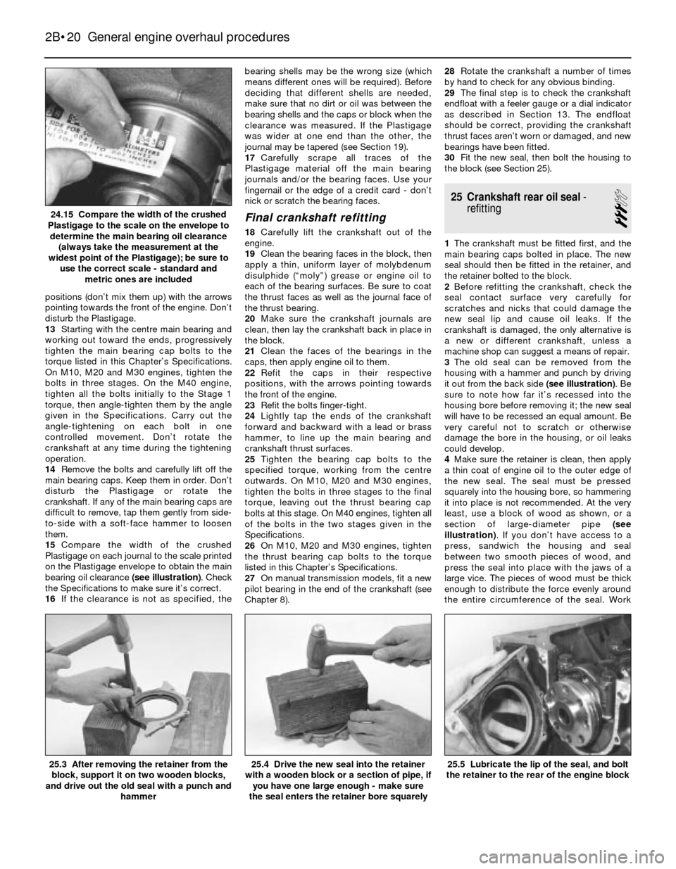
15Compare the width of the crushed
Plastigage on each journal to the scale printed
on the Plastigage envelope to obtain the main
bearing oil clearance (see illustration). Check
the Specifications to make sure it’s correct.
16If the clearance is not as specified, thebearing shells may be the wrong size (which
means different ones will be required). Before
deciding that different shells are needed,
make sure that no dirt or oil was between the
bearing shells and the caps or block when the
clearance was measured. If the Plastigage
was wider at one end than the other, the
journal may be tapered (see Section 19).
17Carefully scrape all traces of the
Plastigage material off the main bearing
journals and/or the bearing faces. Use your
fingernail or the edge of a credit card - don’t
nick or scratch the bearing faces.
Final crankshaft refitting
18Carefully lift the crankshaft out of the
engine.
19Clean the bearing faces in the block, then
apply a thin, uniform layer of molybdenum
disulphide (“moly”) grease or engine oil to
each of the bearing surfaces. Be sure to coat
the thrust faces as well as the journal face of
the thrust bearing.
20Make sure the crankshaft journals are
clean, then lay the crankshaft back in place in
the block.
21Clean the faces of the bearings in the
caps, then apply engine oil to them.
22Refit the caps in their respective
positions, with the arrows pointing towards
the front of the engine.
23Refit the bolts finger-tight.
24Lightly tap the ends of the crankshaft
forward and backward with a lead or brass
hammer, to line up the main bearing and
crankshaft thrust surfaces.
25Tighten the bearing cap bolts to the
specified torque, working from the centre
outwards. On M10, M20 and M30 engines,
tighten the bolts in three stages to the final
torque, leaving out the thrust bearing cap
bolts at this stage. On M40 engines, tighten all
of the bolts in the two stages given in the
Specifications.
26On M10, M20 and M30 engines, tighten
the thrust bearing cap bolts to the torque
listed in this Chapter’s Specifications.
27On manual transmission models, fit a new
pilot bearing in the end of the crankshaft (see
Chapter 8).28Rotate the crankshaft a number of times
by hand to check for any obvious binding.
29The final step is to check the crankshaft
endfloat with a feeler gauge or a dial indicator
as described in Section 13. The endfloat
should be correct, providing the crankshaft
thrust faces aren’t worn or damaged, and new
bearings have been fitted.
30Fit the new seal, then bolt the housing to
the block (see Section 25).
25 Crankshaft rear oil seal-
refitting
3
1The crankshaft must be fitted first, and the
main bearing caps bolted in place. The new
seal should then be fitted in the retainer, and
the retainer bolted to the block.
2Before refitting the crankshaft, check the
seal contact surface very carefully for
scratches and nicks that could damage the
new seal lip and cause oil leaks. If the
crankshaft is damaged, the only alternative is
a new or different crankshaft, unless a
machine shop can suggest a means of repair.
3The old seal can be removed from the
housing with a hammer and punch by driving
it out from the back side (see illustration). Be
sure to note how far it’s recessed into the
housing bore before removing it; the new seal
will have to be recessed an equal amount. Be
very careful not to scratch or otherwise
damage the bore in the housing, or oil leaks
could develop.
4Make sure the retainer is clean, then apply
a thin coat of engine oil to the outer edge of
the new seal. The seal must be pressed
squarely into the housing bore, so hammering
it into place is not recommended. At the very
least, use a block of wood as shown, or a
section of large-diameter pipe (see
illustration). If you don’t have access to a
press, sandwich the housing and seal
between two smooth pieces of wood, and
press the seal into place with the jaws of a
large vice. The pieces of wood must be thick
enough to distribute the force evenly around
the entire circumference of the seal. Work
2B•20 General engine overhaul procedures
25.5 Lubricate the lip of the seal, and bolt
the retainer to the rear of the engine block25.4 Drive the new seal into the retainer
with a wooden block or a section of pipe, if
you have one large enough - make sure
the seal enters the retainer bore squarely25.3 After removing the retainer from the
block, support it on two wooden blocks,
and drive out the old seal with a punch and
hammer
24.15 Compare the width of the crushed
Plastigage to the scale on the envelope to
determine the main bearing oil clearance
(always take the measurement at the
widest point of the Plastigage); be sure to
use the correct scale - standard and
metric ones are included
Page 79 of 228
3General
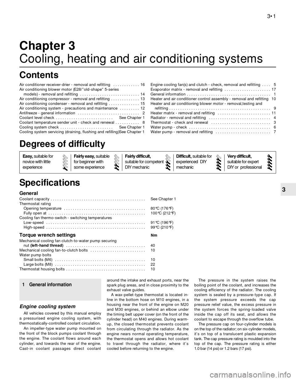
Coolant capacity . . . . . . . . . . . . . . . . . . . . . . . . . . . . . . . . . . . . . . . . . . . See Chapter 1
Thermostat rating
Opening temperature . . . . . . . . . . . . . . . . . . . . . . . . . . . . . . . . . . . . . 80°C (176°F)
Fully open at . . . . . . . . . . . . . . . . . . . . . . . . . . . . . . . . . . . . . . . . . . . . 100°C (212°F)
Cooling fan thermo-switch - switching temperatures
Low-speed . . . . . . . . . . . . . . . . . . . . . . . . . . . . . . . . . . . . . . . . . . . . . 91°C (196°F)
High-speed . . . . . . . . . . . . . . . . . . . . . . . . . . . . . . . . . . . . . . . . . . . . . 99°C (210°F)
Torque wrench settingsNm
Mechanical cooling fan clutch-to-water pump securing
nut (left-hand thread) . . . . . . . . . . . . . . . . . . . . . . . . . . . . . . . . . . . . 40
Mechanical cooling fan-to-clutch bolts . . . . . . . . . . . . . . . . . . . . . . . . . 10
Water pump bolts
Small bolts (M6) . . . . . . . . . . . . . . . . . . . . . . . . . . . . . . . . . . . . . . . . . 10
Large bolts (M8) . . . . . . . . . . . . . . . . . . . . . . . . . . . . . . . . . . . . . . . . . 22
Thermostat housing bolts . . . . . . . . . . . . . . . . . . . . . . . . . . . . . . . . . . . . 10
Chapter 3
Cooling, heating and air conditioning systems
Air conditioner receiver-drier - removal and refitting . . . . . . . . . . . . 16
Air conditioning blower motor (E28/”old-shape” 5-series
models) - removal and refitting . . . . . . . . . . . . . . . . . . . . . . . . . . . 14
Air conditioning compressor - removal and refitting . . . . . . . . . . . . . 13
Air conditioning condenser - removal and refitting . . . . . . . . . . . . . . 15
Air conditioning system - precautions and maintenance . . . . . . . . . 12
Antifreeze - general information . . . . . . . . . . . . . . . . . . . . . . . . . . . . 2
Coolant level check . . . . . . . . . . . . . . . . . . . . . . . . . . See Chapter 1
Coolant temperature sender unit - check and renewal . . . . . . . . . . . 8
Cooling system check . . . . . . . . . . . . . . . . . . . . . . . . See Chapter 1
Cooling system servicing (draining, flushing and refilling)See Chapter 1Engine cooling fan(s) and clutch - check, removal and refitting . . . . 5
Evaporator matrix - removal and refitting . . . . . . . . . . . . . . . . . . . . . 17
General information . . . . . . . . . . . . . . . . . . . . . . . . . . . . . . . . . . . . . . 1
Heater and air conditioner control assembly - removal and refitting 10
Heater and air conditioning blower motor - removal,testing and
refitting . . . . . . . . . . . . . . . . . . . . . . . . . . . . . . . . . . . . . . . . . . . . . . 9
Heater matrix - removal and refitting . . . . . . . . . . . . . . . . . . . . . . . . 11
Radiator - removal and refitting . . . . . . . . . . . . . . . . . . . . . . . . . . . . 4
Thermostat - check and renewal . . . . . . . . . . . . . . . . . . . . . . . . . . . 3
Water pump - check . . . . . . . . . . . . . . . . . . . . . . . . . . . . . . . . . . . . . 6
Water pump - removal and refitting . . . . . . . . . . . . . . . . . . . . . . . . . 7
3•1
Easy,suitable for
novice with little
experienceFairly easy,suitable
for beginner with
some experienceFairly difficult,
suitable for competent
DIY mechanic
Difficult,suitable for
experienced DIY
mechanicVery difficult,
suitable for expert
DIY or professional
Degrees of difficulty
Specifications Contents
1 General information
Engine cooling system
All vehicles covered by this manual employ
a pressurised engine cooling system, with
thermostatically-controlled coolant circulation.
An impeller-type water pump mounted on
the front of the block pumps coolant through
the engine. The coolant flows around each
cylinder, and towards the rear of the engine.
Cast-in coolant passages direct coolantaround the intake and exhaust ports, near the
spark plug areas, and in close proximity to the
exhaust valve guides.
A wax-pellet-type thermostat is located in-
line in the bottom hose on M10 engines, in a
housing near the front of the engine on M20
and M30 engines, or behind an elbow under
the timing belt upper cover (on the front of the
cylinder head) on M40 engines. During warm-
up, the closed thermostat prevents coolant
from circulating through the radiator. As the
engine nears normal operating temperature,
the thermostat opens and allows hot coolant
to travel through the radiator, where it’s
cooled before returning to the engine.The pressure in the system raises the
boiling point of the coolant, and increases the
cooling efficiency of the radiator. The cooling
system is sealed by a pressure-type cap. If
the system pressure exceeds the cap
pressure relief value, the excess pressure in
the system forces the spring-loaded valve
inside the cap off its seat, and allows the
coolant to escape through the overflow tube.
The pressure cap on four-cylinder models is
on the top of the radiator; on six-cylinder models,
it’s on top of a translucent plastic expansion
tank. The cap pressure rating is moulded into the
top of the cap. The pressure rating is either
1.0 bar (14 psi) or 1.2 bars (17 psi).
Page 80 of 228
Warning: Do not remove the
pressure cap from the radiator or
expansion tank until the engine
has cooled completely and
there’s no pressure remaining in the
cooling system. Removing the cap from a
hot engine risks personal injury by
scalding.
Heating system
The heating system consists of a blower fan
and heater matrix located in the heater box,
with hoses connecting the heater matrix to the
engine cooling system, and the heater/air
conditioning control head on the dashboard.
Hot engine coolant is circulated through the
heater matrix passages all the time the engine
is running. Switching the heater on opens a
flap door to direct air through the heater
matrix, and the warmed air enters the
passenger compartment. A fan switch on the
control head activates the blower motor,
which forces more air through the heater
matrix, giving additional heater output for
demisting, etc.
Air conditioning system
The air conditioning system consists of a
condenser mounted in front of the radiator, an
evaporator mounted adjacent to the heater
matrix, a compressor mounted on the engine,
a filter-drier (receiver-drier) which contains a
high-pressure relief valve, and the plumbing
connecting all of the above components.
A blower fan forces the warmer air of the
passenger compartment through the
evaporator matrix (a radiator-in-reverse),
transferring the heat from the air to the
refrigerant. The liquid refrigerant boils off into
low-pressure vapour, taking the heat with it
when it leaves the evaporator.
Note: Refer to the precautions at the start
of Section 12 concerning the potential
dangers associated with the air conditioning
system.
2 Antifreeze-
general information
Warning: Do not allow antifreeze
to come in contact with your skin
or painted surfaces of the
vehicle. Rinse off spills
immediately with plenty of water. If
consumed, antifreeze can be fatal;
children and pets are attracted by its
sweet taste, so wipe up garage floor and
drip pan coolant spills immediately. Keep
antifreeze containers covered, and repair
leaks in your cooling system as soon as
they are noticed.
The cooling system should be filled with a
60/40% water/ethylene-glycol-based anti-
freeze solution, which will prevent freezing
down to approximately -27°C (-17°F). The
antifreeze also raises the boiling point of thecoolant, and (if of good quality) provides
protection against corrosion.
The cooling system should be drained,
flushed and refilled at the specified intervals
(see Chapter 1). Old or contaminated
antifreeze solutions are likely to cause
damage, and encourage the formation of rust
and scale in the system. Use distilled water
with the antifreeze, if available, or clean
rainwater. Tap water will do, but not if the
water in your area is at all “hard”.
Before adding antifreeze, check all hose
connections, because antifreeze tends to
search out and leak through very minute
openings. Engines don’t normally consume
coolant, so if the level goes down, find the
cause and correct it.
The antifreeze mixture should be
maintained at its correct proportions; adding
too much antifreeze reduces the efficiency of
the cooling system. If necessary, consult the
mixture ratio chart on the antifreeze container
before adding coolant. Hydrometers are
available at most car accessory shops to test
the coolant. Use antifreeze which meets the
vehicle manufacturer’s specifications.
3 Thermostat-
check and renewal
1
Warning: Do not remove the
radiator cap, drain the coolant, or
renew the thermostat until the
engine has cooled completely.
Check
1Before assuming the thermostat is to blame
for a cooling system problem, check the
coolant level, drivebelt tension (see Chapter 1)
and temperature gauge (or warning light)
operation.
2If the engine seems to be taking a long time
to warm up (based on heater output or
temperature gauge operation), the thermostat
is probably stuck open. Renew the
thermostat.
3If the engine runs hot, use your hand to
check the temperature of the upper radiator
hose. If the hose isn’t hot, but the engine is,
the thermostat is probably stuck closed,preventing the coolant inside the engine from
circulating to the radiator. Renew the
thermostat.
Caution: Don’t drive the vehicle
without a thermostat. The engine
will be very slow to warm-up in
cold conditions, resulting in poor
fuel economy and driveability. A new
thermostat is normally an inexpensive
component anyway.
4If the upper radiator hose is hot, it means
that the coolant is flowing and the thermostat
is at least partly open. Consult the “Fault
finding” Section at the rear of this manual for
cooling system diagnosis.
Renewal
All models
5Disconnect the negative cable from the
battery.
Caution: If the radio in your
vehicle is equipped with an anti-
theft system, make sure you
have the correct activation code
before disconnecting the battery.
Note: If, after connecting the battery, the
wrong language appears on the instrument
panel display, refer to page 0-7 for the
language resetting procedure.
6Drain the cooling system (see Chapter 1). If
the coolant is relatively new or in good
condition, save it and re-use it.
M10 engines
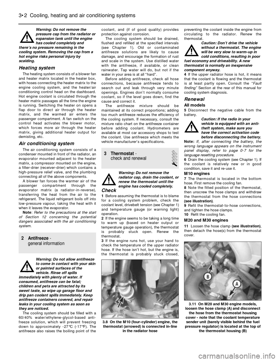
7The thermostat is located in the bottom
hose. First remove the cooling fan.
8Note the fitted position of the thermostat,
then unscrew the hose clamps and withdraw
the thermostat from the hose connections
(see illustration).
9Refit the thermostat-to-hose connections,
and tighten the hose clamps.
10Refit the cooling fan.
M20 and M30 engines
11Loosen the hose clamp (see illustration),
then detach the hose(s) from the thermostat
cover.
3•2 Cooling, heating and air conditioning systems
3.11 On M20 and M30 engine models,
loosen the hose clamp (A) and disconnect
the hose from the thermostat housing
cover - note that the coolant temperature
sender unit (barely visible behind the fuel
pressure regulator) is located at the top of
the thermostat housing (B)
3.8 On the M10 (four-cylinder) engine, the
thermostat (arrowed) is connected in-line
in the radiator hose
Page 84 of 228
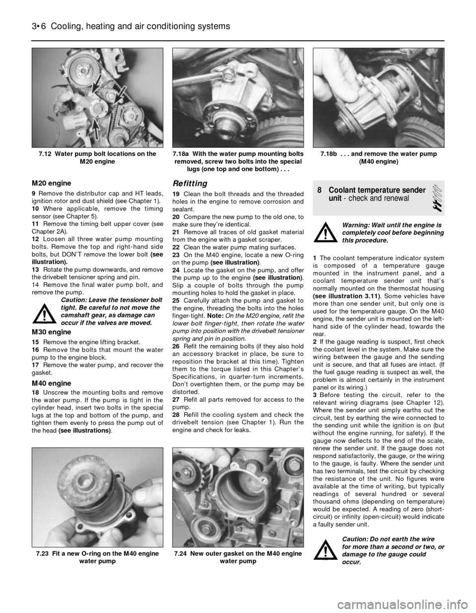
M20 engine
9Remove the distributor cap and HT leads,
ignition rotor and dust shield (see Chapter 1).
10Where applicable, remove the timing
sensor (see Chapter 5).
11Remove the timing belt upper cover (see
Chapter 2A).
12Loosen all three water pump mounting
bolts. Remove the top and right-hand side
bolts, but DON’T remove the lower bolt (see
illustration).
13Rotate the pump downwards, and remove
the drivebelt tensioner spring and pin.
14 Remove the final water pump bolt, and
remove the pump.
Caution: Leave the tensioner bolt
tight. Be careful to not move the
camshaft gear, as damage can
occur if the valves are moved.
M30 engine
15Remove the engine lifting bracket.
16Remove the bolts that mount the water
pump to the engine block.
17Remove the water pump, and recover the
gasket.
M40 engine
18Unscrew the mounting bolts and remove
the water pump. If the pump is tight in the
cylinder head, insert two bolts in the special
lugs at the top and bottom of the pump, and
tighten them evenly to press the pump out of
the head (see illustrations).
Refitting
19Clean the bolt threads and the threaded
holes in the engine to remove corrosion and
sealant.
20Compare the new pump to the old one, to
make sure they’re identical.
21Remove all traces of old gasket material
from the engine with a gasket scraper.
22Clean the water pump mating surfaces.
23On the M40 engine, locate a new O-ring
on the pump (see illustration).
24Locate the gasket on the pump, and offer
the pump up to the engine (see illustration).
Slip a couple of bolts through the pump
mounting holes to hold the gasket in place.
25Carefully attach the pump and gasket to
the engine, threading the bolts into the holes
finger-tight.Note:On the M20 engine, refit the
lower bolt finger-tight, then rotate the water
pump into position with the drivebelt tensioner
spring and pin in position.
26Refit the remaining bolts (if they also hold
an accessory bracket in place, be sure to
reposition the bracket at this time). Tighten
them to the torque listed in this Chapter’s
Specifications, in quarter-turn increments.
Don’t overtighten them, or the pump may be
distorted.
27Refit all parts removed for access to the
pump.
28Refill the cooling system and check the
drivebelt tension (see Chapter 1). Run the
engine and check for leaks.8 Coolant temperature sender
unit- check and renewal
2
Warning: Wait until the engine is
completely cool before beginning
this procedure.
1The coolant temperature indicator system
is composed of a temperature gauge
mounted in the instrument panel, and a
coolant temperature sender unit that’s
normally mounted on the thermostat housing
(see illustration 3.11). Some vehicles have
more than one sender unit, but only one is
used for the temperature gauge. On the M40
engine, the sender unit is mounted on the left-
hand side of the cylinder head, towards the
rear.
2If the gauge reading is suspect, first check
the coolant level in the system. Make sure the
wiring between the gauge and the sending
unit is secure, and that all fuses are intact. (If
the fuel gauge reading is suspect as well, the
problem is almost certainly in the instrument
panel or its wiring.)
3Before testing the circuit, refer to the
relevant wiring diagrams (see Chapter 12).
Where the sender unit simply earths out the
circuit, test by earthing the wire connected to
the sending unit while the ignition is on (but
without the engine running, for safety). If the
gauge now deflects to the end of the scale,
renew the sender unit. If the gauge does not
respond satisfactorily, the gauge, or the wiring
to the gauge, is faulty. Where the sender unit
has two terminals, test the circuit by checking
the resistance of the unit. No figures were
available at the time of writing, but typically
readings of several hundred or several
thousand ohms (depending on temperature)
would be expected. A reading of zero (short-
circuit) or infinity (open-circuit) would indicate
a faulty sender unit.
Caution: Do not earth the wire
for more than a second or two, or
damage to the gauge could
occur.
3•6 Cooling, heating and air conditioning systems
7.24 New outer gasket on the M40 engine
water pump7.23 Fit a new O-ring on the M40 engine
water pump
7.18b . . . and remove the water pump
(M40 engine)7.18a With the water pump mounting bolts
removed, screw two bolts into the special
lugs (one top and one bottom) . . .7.12 Water pump bolt locations on the
M20 engine
Page 86 of 228
12Disconnect the cables from the clips
securing them to the lever assembly, marking
them for accurate refitting.
13Disconnect the electrical connection from
the control assembly.
14Remove the screws attaching the bezel to
the control assembly, and remove the control
assembly.
Refitting
15Refitting is the reverse of the removal
procedure.
11 Heater matrix-
removal and refitting
1
Caution: If the radio in your
vehicle is equipped with an anti-
theft system, make sure you
have the correct activation code
before disconnecting the battery.
Note: If, after connecting the battery, the
wrong language appears on the instrument
panel display, refer to page 0-7 for the
language resetting procedure.
1Disconnect the battery negative cable.
2Drain the cooling system (see Chapter 1).
3Remove the centre console (see Chap-
ter 11). Spread an old blanket over the front
carpeting; this will prevent stains if any
residual coolant spills.
Removal
3-Series models
4Remove the left-hand side heater ducting,
and set it aside.
5Remove the heater valve clamp.
6Remove the screws and detach the flange
where the two coolant lines enter the heater
matrix case. Be careful; some coolant may
spill.
7Remove the two screws holding the heater
matrix case to the heater main assembly.
8Slide the heater matrix out of the mounting.
Be careful not to spill any of the remaining
coolant in the heater matrix when removing it.
5-Series models
9Disconnect the temperature sensor
electrical connectors.
10Disconnect the straps holding the wiring
to the case, and set the wiring out of the way.
11Unfasten the cover fasteners.
12Remove the screws holding the cover in
place, then remove the cover.
13Disconnect all heater pipe connections
attached to the heater matrix. Be careful;
some coolant may spill.
14Lifting on the right side of the heater
matrix first, remove the heater matrix.
Refitting
Note: Always use new O-rings when attaching
the coolant lines to the heater matrix.15Refitting is the reverse of removal. Refill
the cooling system (see Chapter 1), then run
the engine with the heater on, and check for
correct operation and leaks.
12 Air conditioning system-
precautions and maintenance
1
Precautions
Warning: The air conditioning
system is under high pressure.
DO NOT loosen any hose or line
fittings, or remove any
components, until after the system has
been discharged. Air conditioning
refrigerant should be properly discharged
by a qualified refrigeration engineer. The
refrigerant used in the system must not be
allowed into contact with your skin or
eyes, or there is a risk of frostbite. Should
the refrigerant come into contact with a
naked flame, a poisonous gas will be
produced. Smoking in the presence of
refrigerant is therefore highly dangerous,
particularly if refrigerant vapour is inhaled
through a lighted cigarette. The refrigerant
is heavier than air, and it may cause
suffocation if discharged in an enclosed
space such as a domestic garage.
Finally, uncontrolled release of the
refrigerant causes environmental damage,
by contributing to the “greenhouse
effect”.
Maintenance
1The following maintenance checks should
be performed on a regular basis to ensure the
air conditioner continues to operate at peak
efficiency:
a) Check the drivebelt. If it’s worn or
deteriorated, renew it (see Chapter 1).
b) Check the system hoses. Look for cracks,
bubbles, hard spots and deterioration.
Inspect the hoses and all fittings for oil
bubbles and seepage. If there’s any
evidence of wear, damage or leaks, have
new hose(s) fitted.
c) Inspect the condenser fins for leaves, flies
and other debris. Use a “fin comb” or
compressed air to clean the condenser.
d) Make sure the system has the correct
refrigerant charge, as described below.
2It’s a good idea to operate the system for
about 10 minutes at least once a month,
particularly during the winter. Long-term non-
use can cause hardening, and subsequent
failure, of the seals.
3Because of the complexity of the air
conditioning system and the special
equipment necessary to service it, in-depth
fault diagnosis and repair procedures are not
included in this manual. However, simple
checks and component renewal procedures
are provided in this Chapter.
4The most common cause of poor cooling issimply a low system refrigerant charge. If a
noticeable loss of cool air output occurs, the
following quick check may help you determine
if the refrigerant level is low.
5Warm the engine up to normal operating
temperature.
6Set the air conditioning temperature
selector at the coldest setting, and put the
blower at the highest setting. Open the doors
(to make sure the air conditioning system
doesn’t switch off as soon as it cools the
passenger compartment).
7With the compressor engaged - the
compressor clutch will make an audible click,
and the centre of the clutch will rotate - feel
the tube located adjacent to the right front
frame rail, near the radiator.
8If a significant temperature drop is noticed,
the refrigerant level is probably OK.
9If the inlet line has frost accumulation, or
feels cooler than the receiver-drier surface,
the refrigerant charge is low. Recharging the
system should be carried out by a qualified
refrigeration engineer.
13 Air conditioning compressor
- removal and refitting
5
Warning: Due to the potential
dangers associated with the
system, you are strongly advised
to have any work on the air
conditioning system carried out by a BMW
dealer or air conditioning specialist. At the
very least, DO NOT dismantle any part of
the system (hoses, compressor, line
fittings, etc.) until after the system has
been discharged by a qualified engineer.
Refer to the precautions given at the start
of Section 12.
Note: If a new compressor is fitted, the
receiver-drier (see Section 16) should also be
renewed.
Removal
1Have the air conditioning system
discharged (see Warning above).
2Disconnect the battery negative cable.
Caution: If the radio in your
vehicle is equipped with an anti-
theft system, make sure you
have the correct activation code
before disconnecting the battery.
Note: If, after connecting the battery, the
wrong language appears on the instrument
panel display, refer to page 0-7 for the
language resetting procedure.
3Disconnect the compressor clutch wiring
harness.
4Remove the drivebelt (see Chapter 1).
5Disconnect the refrigerant lines from the
rear of the compressor. Plug the open fittings
to prevent entry of dirt and moisture.
6Unbolt the compressor from the mounting
3•8 Cooling, heating and air conditioning systems