Rear BMW 3 SERIES 1989 E30 Manual PDF
[x] Cancel search | Manufacturer: BMW, Model Year: 1989, Model line: 3 SERIES, Model: BMW 3 SERIES 1989 E30Pages: 228, PDF Size: 7.04 MB
Page 174 of 228
13 Headlights- adjustment
2
Note:The headlights must be aimed correctly.
If adjusted incorrectly, they could momentarily
blind the driver of an oncoming vehicle and
cause a serious accident, or seriously reduce
your ability to see the road. The headlights
should be checked for proper aim every
12 months (as is done during the MOT test),
and any time a new headlight is fitted or front-
end body work is performed. It should be
emphasised that the following procedure will
only provide a temporary setting until the
headlights can be adjusted by a properly-
equipped garage.
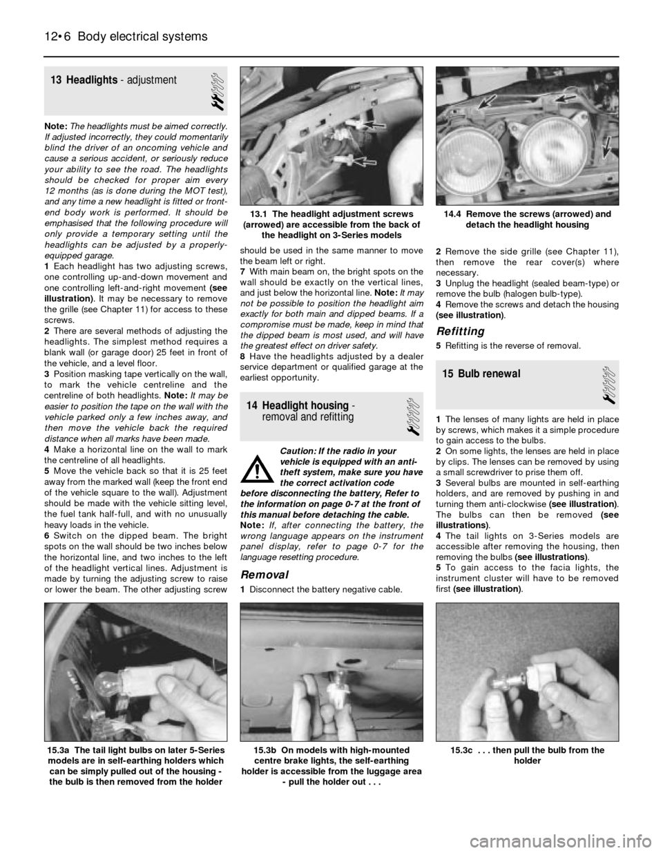
1Each headlight has two adjusting screws,
one controlling up-and-down movement and
one controlling left-and-right movement (see
illustration). It may be necessary to remove
the grille (see Chapter 11) for access to these
screws.
2There are several methods of adjusting the
headlights. The simplest method requires a
blank wall (or garage door) 25 feet in front of
the vehicle, and a level floor.
3Position masking tape vertically on the wall,
to mark the vehicle centreline and the
centreline of both headlights. Note:It may be
easier to position the tape on the wall with the
vehicle parked only a few inches away, and
then move the vehicle back the required
distance when all marks have been made.
4Make a horizontal line on the wall to mark
the centreline of all headlights.
5Move the vehicle back so that it is 25 feet
away from the marked wall (keep the front end
of the vehicle square to the wall). Adjustment
should be made with the vehicle sitting level,
the fuel tank half-full, and with no unusually
heavy loads in the vehicle.
6Switch on the dipped beam. The bright
spots on the wall should be two inches below
the horizontal line, and two inches to the left
of the headlight vertical lines. Adjustment is
made by turning the adjusting screw to raise
or lower the beam. The other adjusting screwshould be used in the same manner to move
the beam left or right.
7With main beam on, the bright spots on the
wall should be exactly on the vertical lines,
and just below the horizontal line. Note:It may
not be possible to position the headlight aim
exactly for both main and dipped beams. If a
compromise must be made, keep in mind that
the dipped beam is most used, and will have
the greatest effect on driver safety.
8Have the headlights adjusted by a dealer
service department or qualified garage at the
earliest opportunity.
14 Headlight housing-
removal and refitting
1
Caution: If the radio in your
vehicle is equipped with an anti-
theft system, make sure you have
the correct activation code
before disconnecting the battery, Refer to
the information on page 0-7 at the front of
this manual before detaching the cable.
Note: If, after connecting the battery, the
wrong language appears on the instrument
panel display, refer to page 0-7 for the
language resetting procedure.
Removal
1Disconnect the battery negative cable.2Remove the side grille (see Chapter 11),
then remove the rear cover(s) where
necessary.
3Unplug the headlight (sealed beam-type) or
remove the bulb (halogen bulb-type).
4Remove the screws and detach the housing
(see illustration).
Refitting
5Refitting is the reverse of removal.
15 Bulb renewal
1
1The lenses of many lights are held in place
by screws, which makes it a simple procedure
to gain access to the bulbs.
2On some lights, the lenses are held in place
by clips. The lenses can be removed by using
a small screwdriver to prise them off.
3Several bulbs are mounted in self-earthing
holders, and are removed by pushing in and
turning them anti-clockwise (see illustration).
The bulbs can then be removed (see
illustrations).
4The tail lights on 3-Series models are
accessible after removing the housing, then
removing the bulbs (see illustrations).
5To gain access to the facia lights, the
instrument cluster will have to be removed
first (see illustration).
12•6 Body electrical systems
15.3c . . . then pull the bulb from the
holder15.3b On models with high-mounted
centre brake lights, the self-earthing
holder is accessible from the luggage area
- pull the holder out . . .15.3a The tail light bulbs on later 5-Series
models are in self-earthing holders which
can be simply pulled out of the housing -
the bulb is then removed from the holder
14.4 Remove the screws (arrowed) and
detach the headlight housing13.1 The headlight adjustment screws
(arrowed) are accessible from the back of
the headlight on 3-Series models
Page 175 of 228
16 Windscreen/tailgate wiper
motor- removal and refitting
2
Caution: If the radio in your
vehicle is equipped with an anti-
theft system, make sure you have
the correct activation code
before disconnecting the battery, Refer to
the information on page 0-7 at the front of
this manual before detaching the cable.
Note: If, after connecting the battery, the
wrong language appears on the instrument
panel display, refer to page 0-7 for the
language resetting procedure.
1Disconnect the battery negative cable.
Windscreen wiper motor
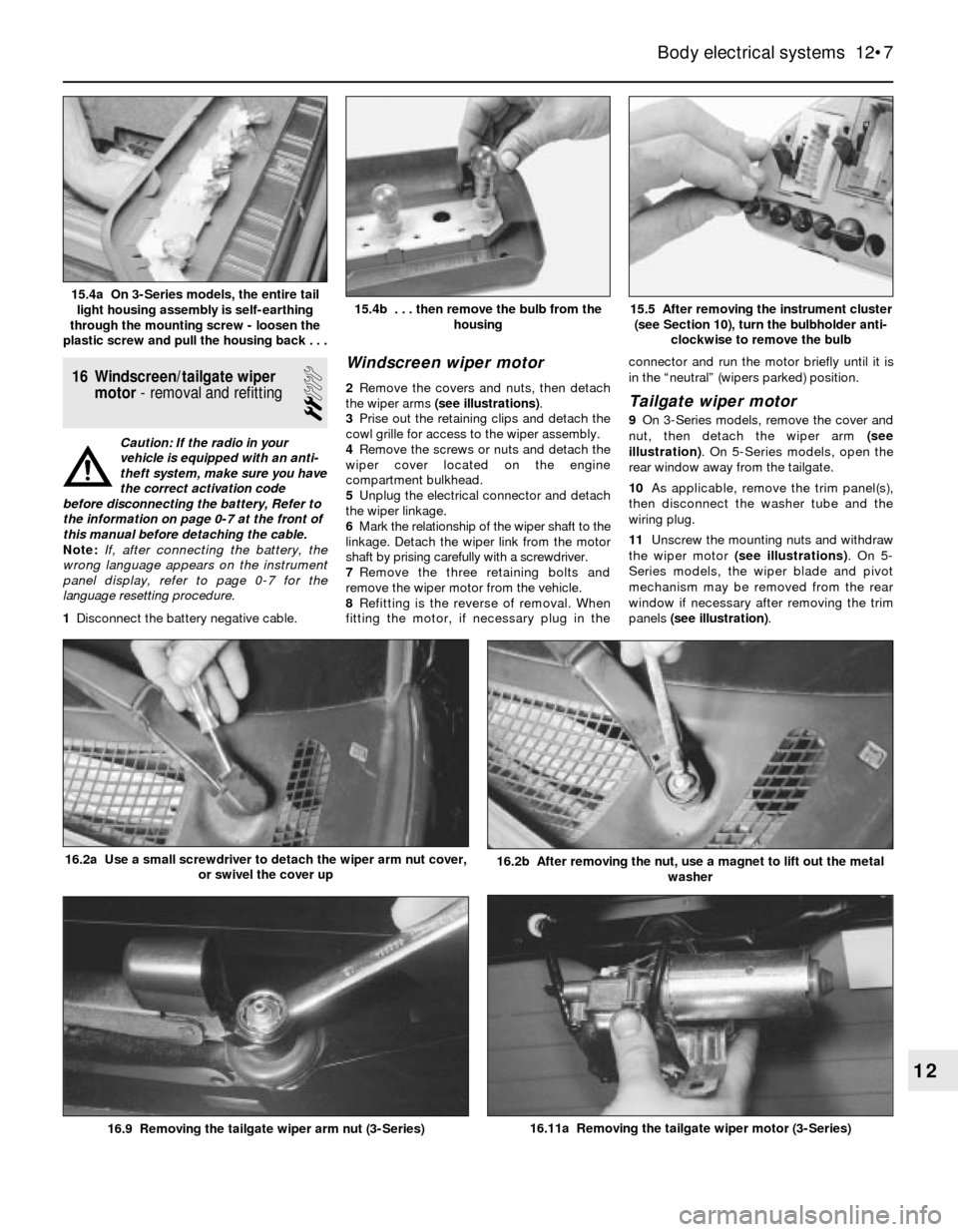
2Remove the covers and nuts, then detach
the wiper arms (see illustrations).
3Prise out the retaining clips and detach the
cowl grille for access to the wiper assembly.
4Remove the screws or nuts and detach the
wiper cover located on the engine
compartment bulkhead.
5Unplug the electrical connector and detach
the wiper linkage.
6Mark the relationship of the wiper shaft to the
linkage. Detach the wiper link from the motor
shaft by prising carefully with a screwdriver.
7Remove the three retaining bolts and
remove the wiper motor from the vehicle.
8Refitting is the reverse of removal. When
fitting the motor, if necessary plug in theconnector and run the motor briefly until it is
in the “neutral” (wipers parked) position.Tailgate wiper motor
9On 3-Series models, remove the cover and
nut, then detach the wiper arm (see
illustration). On 5-Series models, open the
rear window away from the tailgate.
10As applicable, remove the trim panel(s),
then disconnect the washer tube and the
wiring plug.
11Unscrew the mounting nuts and withdraw
the wiper motor (see illustrations). On 5-
Series models, the wiper blade and pivot
mechanism may be removed from the rear
window if necessary after removing the trim
panels (see illustration).
Body electrical systems 12•7
15.5 After removing the instrument cluster
(see Section 10), turn the bulbholder anti-
clockwise to remove the bulb15.4b . . . then remove the bulb from the
housing15.4a On 3-Series models, the entire tail
light housing assembly is self-earthing
through the mounting screw - loosen the
plastic screw and pull the housing back . . .
16.11a Removing the tailgate wiper motor (3-Series)
16.2b After removing the nut, use a magnet to lift out the metal
washer16.2a Use a small screwdriver to detach the wiper arm nut cover,
or swivel the cover up
16.9 Removing the tailgate wiper arm nut (3-Series)
12
Page 176 of 228
12Refitting is a reversal of removal. When
fitting the motor, if necessary plug in the
connector and run the motor briefly until it is
in the “neutral” (wiper parked) position.
17 Heated rear window-
check and repair
2
1The heated rear window consists of a
number of horizontal elements on the glass
surface.
2Small breaks in the element can be repaired
without removing the rear window.
Check
3Switch on the ignition and the heated rear
window.
4Place the positive lead of a voltmeter to the
heater element nearest to the incoming power
source.
5Wrap a piece of aluminium foil around the
negative lead of the voltmeter on the positive
side of the suspected broken element, and
slide it slowly towards the negative side.
Watch the voltmeter needle - when it moves
from zero, you have located the break.
Repair
6Repair the break in the line using a repair kit
recommended specifically for this purpose,
such as BMW repair kit No. 81 22 9 (or
equivalent). Included in this kit is plastic
conductive epoxy. The following paragraphs
give general instructions for this type of repair;
follow the instructions supplied with the repair
kit if they are different.
7Prior to repairing a break, switch off the
circuit and allow it to cool down for a few
minutes.
8Lightly buff the element area with fine steel
wool, then clean it thoroughly.
9Use masking tape to mask off the area of
repair, leaving a slit to which the epoxy can be
applied.
10Mix the epoxy thoroughly, according to
the instructions on the package.
11Apply the epoxy material to the slit in the
masking tape, overlapping the undamaged
area about 20 mm on each end.12Allow the repair to cure for 24 hours
before removing the tape and using the
heated rear window.
18 Supplemental Restraint
System (SRS)- general
information
Later models are equipped with a
Supplemental Restraint System (SRS),
incorporating an airbag. This system is
designed to protect the driver from serious
injury in the event of a head-on or frontal
collision. It consists of an airbag module in the
centre of the steering wheel, two crash
sensors mounted on the front inner wing
panels, and a crash safety switch located
inside the passenger compartment.
The airbag module contains a housing
incorporating the airbag and the inflator units.
The inflator assembly is mounted on the back
of the housing over a hole through which gas
is expelled, inflating the bag almost instanta-
neously when an electrical signal is sent from
the system. This signal is carried by a wire
which is specially wound with several turns,
so the signal will be transmitted regardless of
the steering wheel position.
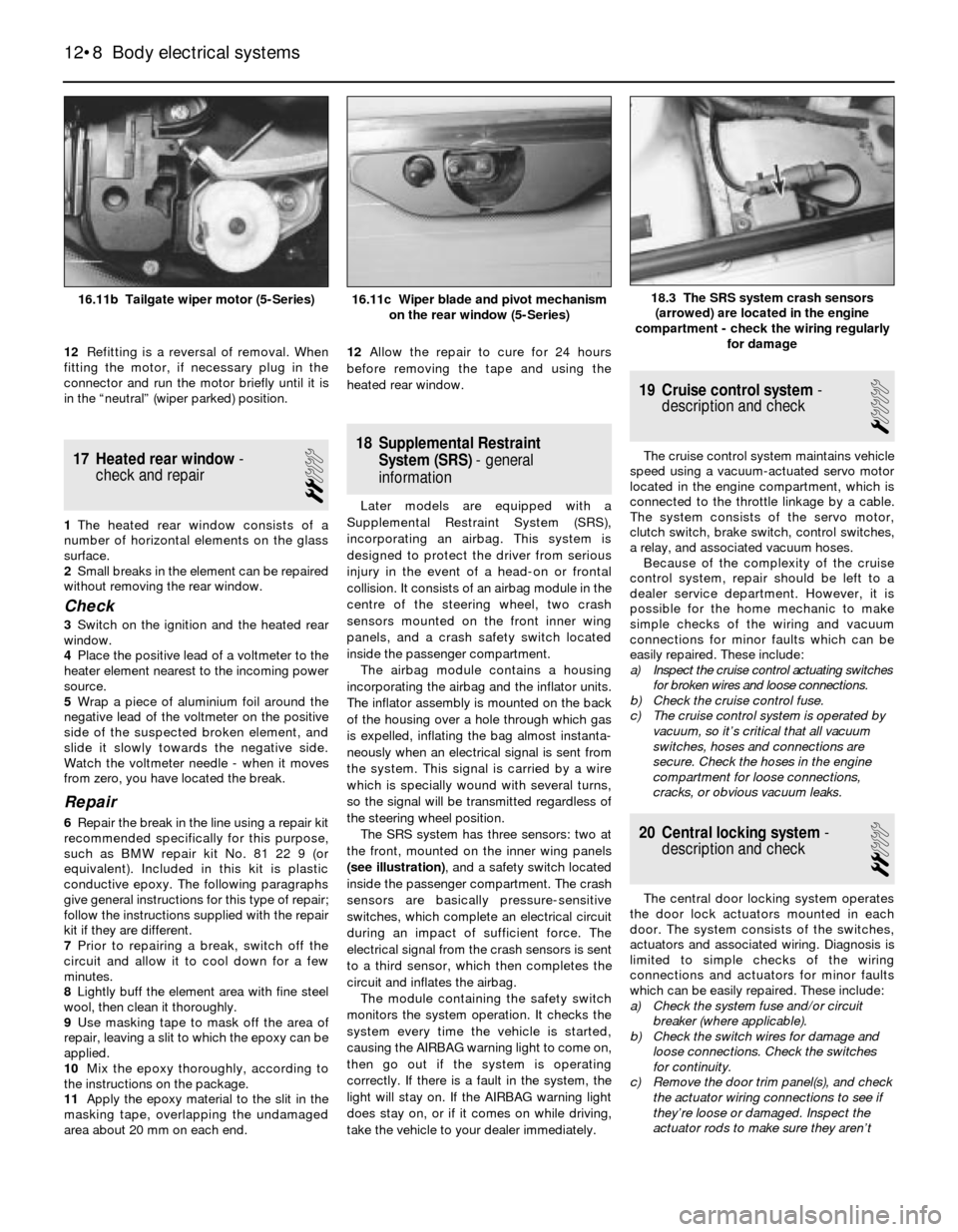
The SRS system has three sensors: two at
the front, mounted on the inner wing panels
(see illustration), and a safety switch located
inside the passenger compartment. The crash
sensors are basically pressure-sensitive
switches, which complete an electrical circuit
during an impact of sufficient force. The
electrical signal from the crash sensors is sent
to a third sensor, which then completes the
circuit and inflates the airbag.
The module containing the safety switch
monitors the system operation. It checks the
system every time the vehicle is started,
causing the AIRBAG warning light to come on,
then go out if the system is operating
correctly. If there is a fault in the system, the
light will stay on. If the AIRBAG warning light
does stay on, or if it comes on while driving,
take the vehicle to your dealer immediately.
19 Cruise control system-
description and check
1
The cruise control system maintains vehicle
speed using a vacuum-actuated servo motor
located in the engine compartment, which is
connected to the throttle linkage by a cable.
The system consists of the servo motor,
clutch switch, brake switch, control switches,
a relay, and associated vacuum hoses.
Because of the complexity of the cruise
control system, repair should be left to a
dealer service department. However, it is
possible for the home mechanic to make
simple checks of the wiring and vacuum
connections for minor faults which can be
easily repaired. These include:
a) Inspect the cruise control actuating switches
for broken wires and loose connections.
b) Check the cruise control fuse.
c) The cruise control system is operated by
vacuum, so it’s critical that all vacuum
switches, hoses and connections are
secure. Check the hoses in the engine
compartment for loose connections,
cracks, or obvious vacuum leaks.
20 Central locking system-
description and check
2
The central door locking system operates
the door lock actuators mounted in each
door. The system consists of the switches,
actuators and associated wiring. Diagnosis is
limited to simple checks of the wiring
connections and actuators for minor faults
which can be easily repaired. These include:
a) Check the system fuse and/or circuit
breaker (where applicable).
b) Check the switch wires for damage and
loose connections. Check the switches
for continuity.
c) Remove the door trim panel(s), and check
the actuator wiring connections to see if
they’re loose or damaged. Inspect the
actuator rods to make sure they aren’t
12•8 Body electrical systems
18.3 The SRS system crash sensors
(arrowed) are located in the engine
compartment - check the wiring regularly
for damage16.11b Tailgate wiper motor (5-Series)16.11c Wiper blade and pivot mechanism
on the rear window (5-Series)
Page 202 of 228
REF•1
REF
MOT Test Checks
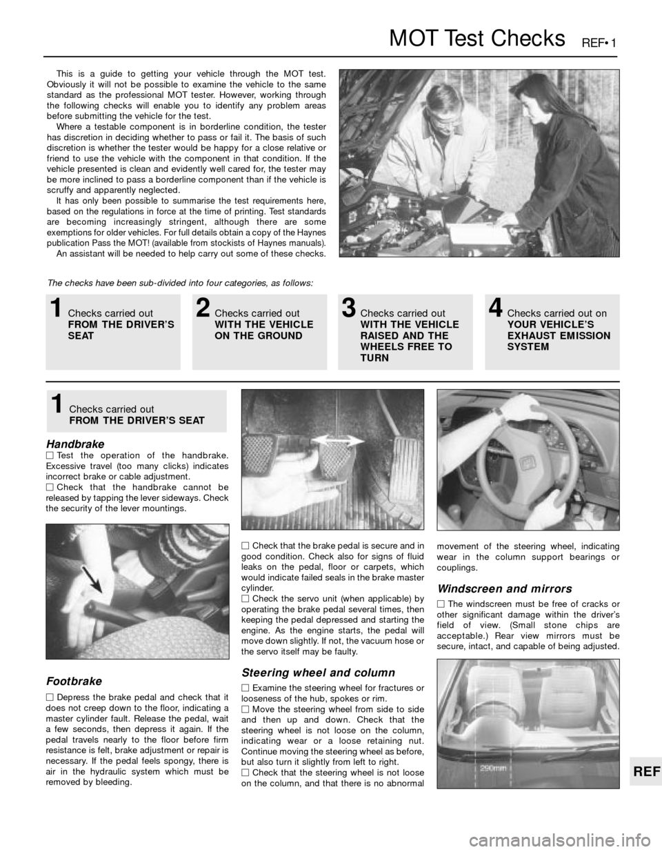
This is a guide to getting your vehicle through the MOT test.
Obviously it will not be possible to examine the vehicle to the same
standard as the professional MOT tester. However, working through
the following checks will enable you to identify any problem areas
before submitting the vehicle for the test.
Where a testable component is in borderline condition, the tester
has discretion in deciding whether to pass or fail it. The basis of such
discretion is whether the tester would be happy for a close relative or
friend to use the vehicle with the component in that condition. If the
vehicle presented is clean and evidently well cared for, the tester may
be more inclined to pass a borderline component than if the vehicle is
scruffy and apparently neglected.
It has only been possible to summarise the test requirements here,
based on the regulations in force at the time of printing. Test standards
are becoming increasingly stringent, although there are some
exemptions for older vehicles. For full details obtain a copy of the Haynes
publication Pass the MOT! (available from stockists of Haynes manuals).
An assistant will be needed to help carry out some of these checks.
The checks have been sub-divided into four categories, as follows:
HandbrakeMTest the operation of the handbrake.
Excessive travel (too many clicks) indicates
incorrect brake or cable adjustment.
MCheck that the handbrake cannot be
released by tapping the lever sideways. Check
the security of the lever mountings.
Footbrake
MDepress the brake pedal and check that it
does not creep down to the floor, indicating a
master cylinder fault. Release the pedal, wait
a few seconds, then depress it again. If the
pedal travels nearly to the floor before firm
resistance is felt, brake adjustment or repair is
necessary. If the pedal feels spongy, there is
air in the hydraulic system which must be
removed by bleeding.MCheck that the brake pedal is secure and in
good condition. Check also for signs of fluid
leaks on the pedal, floor or carpets, which
would indicate failed seals in the brake master
cylinder.
MCheck the servo unit (when applicable) by
operating the brake pedal several times, then
keeping the pedal depressed and starting the
engine. As the engine starts, the pedal will
move down slightly. If not, the vacuum hose or
the servo itself may be faulty.
Steering wheel and column
MExamine the steering wheel for fractures or
looseness of the hub, spokes or rim.
MMove the steering wheel from side to side
and then up and down. Check that the
steering wheel is not loose on the column,
indicating wear or a loose retaining nut.
Continue moving the steering wheel as before,
but also turn it slightly from left to right.
MCheck that the steering wheel is not loose
on the column, and that there is no abnormalmovement of the steering wheel, indicating
wear in the column support bearings or
couplings.
Windscreen and mirrors
MThe windscreen must be free of cracks or
other significant damage within the driver’s
field of view. (Small stone chips are
acceptable.) Rear view mirrors must be
secure, intact, and capable of being adjusted.
1Checks carried out
FROM THE DRIVER’S SEAT
1Checks carried out
FROM THE DRIVER’S
SEAT2Checks carried out
WITH THE VEHICLE
ON THE GROUND3Checks carried out
WITH THE VEHICLE
RAISED AND THE
WHEELS FREE TO
TURN4Checks carried out on
YOUR VEHICLE’S
EXHAUST EMISSION
SYSTEM
Page 203 of 228
REF•2MOT Test Checks
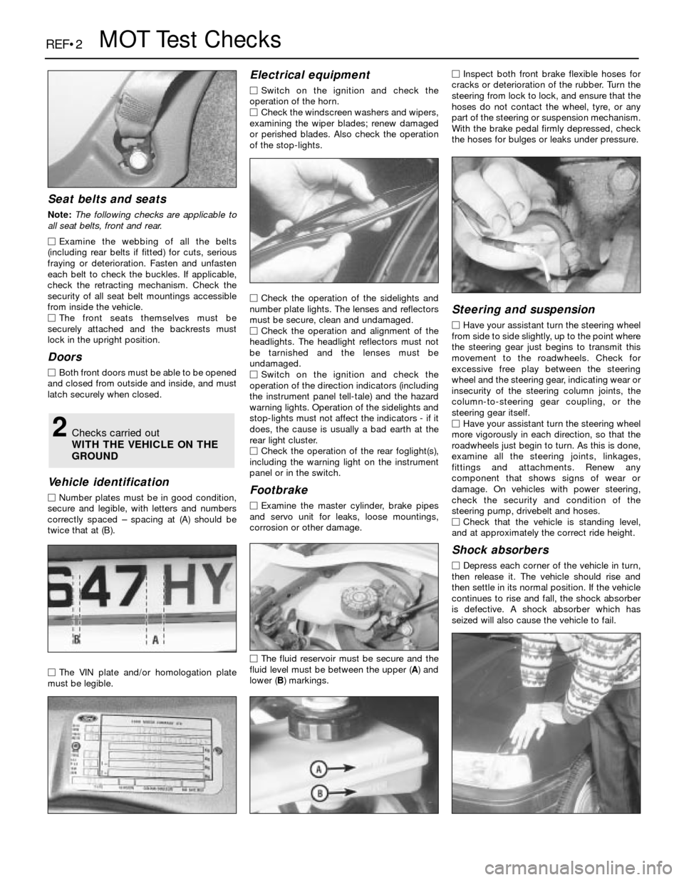
Seat belts and seats
Note: The following checks are applicable to
all seat belts, front and rear.
MExamine the webbing of all the belts
(including rear belts if fitted) for cuts, serious
fraying or deterioration. Fasten and unfasten
each belt to check the buckles. If applicable,
check the retracting mechanism. Check the
security of all seat belt mountings accessible
from inside the vehicle.
MThe front seats themselves must be
securely attached and the backrests must
lock in the upright position.
Doors
MBoth front doors must be able to be opened
and closed from outside and inside, and must
latch securely when closed.
Vehicle identification
MNumber plates must be in good condition,
secure and legible, with letters and numbers
correctly spaced – spacing at (A) should be
twice that at (B).
MThe VIN plate and/or homologation plate
must be legible.
Electrical equipment
MSwitch on the ignition and check the
operation of the horn.
MCheck the windscreen washers and wipers,
examining the wiper blades; renew damaged
or perished blades. Also check the operation
of the stop-lights.
MCheck the operation of the sidelights and
number plate lights. The lenses and reflectors
must be secure, clean and undamaged.
MCheck the operation and alignment of the
headlights. The headlight reflectors must not
be tarnished and the lenses must be
undamaged.
MSwitch on the ignition and check the
operation of the direction indicators (including
the instrument panel tell-tale) and the hazard
warning lights. Operation of the sidelights and
stop-lights must not affect the indicators - if it
does, the cause is usually a bad earth at the
rear light cluster.
MCheck the operation of the rear foglight(s),
including the warning light on the instrument
panel or in the switch.
Footbrake
MExamine the master cylinder, brake pipes
and servo unit for leaks, loose mountings,
corrosion or other damage.
MThe fluid reservoir must be secure and the
fluid level must be between the upper (A) and
lower (B) markings.MInspect both front brake flexible hoses for
cracks or deterioration of the rubber. Turn the
steering from lock to lock, and ensure that the
hoses do not contact the wheel, tyre, or any
part of the steering or suspension mechanism.
With the brake pedal firmly depressed, check
the hoses for bulges or leaks under pressure.
Steering and suspension
MHave your assistant turn the steering wheel
from side to side slightly, up to the point where
the steering gear just begins to transmit this
movement to the roadwheels. Check for
excessive free play between the steering
wheel and the steering gear, indicating wear or
insecurity of the steering column joints, the
column-to-steering gear coupling, or the
steering gear itself.
MHave your assistant turn the steering wheel
more vigorously in each direction, so that the
roadwheels just begin to turn. As this is done,
examine all the steering joints, linkages,
fittings and attachments. Renew any
component that shows signs of wear or
damage. On vehicles with power steering,
check the security and condition of the
steering pump, drivebelt and hoses.
MCheck that the vehicle is standing level,
and at approximately the correct ride height.
Shock absorbers
MDepress each corner of the vehicle in turn,
then release it. The vehicle should rise and
then settle in its normal position. If the vehicle
continues to rise and fall, the shock absorber
is defective. A shock absorber which has
seized will also cause the vehicle to fail.
2Checks carried out
WITH THE VEHICLE ON THE
GROUND
Page 204 of 228
REF•3
REF
MOT Test Checks
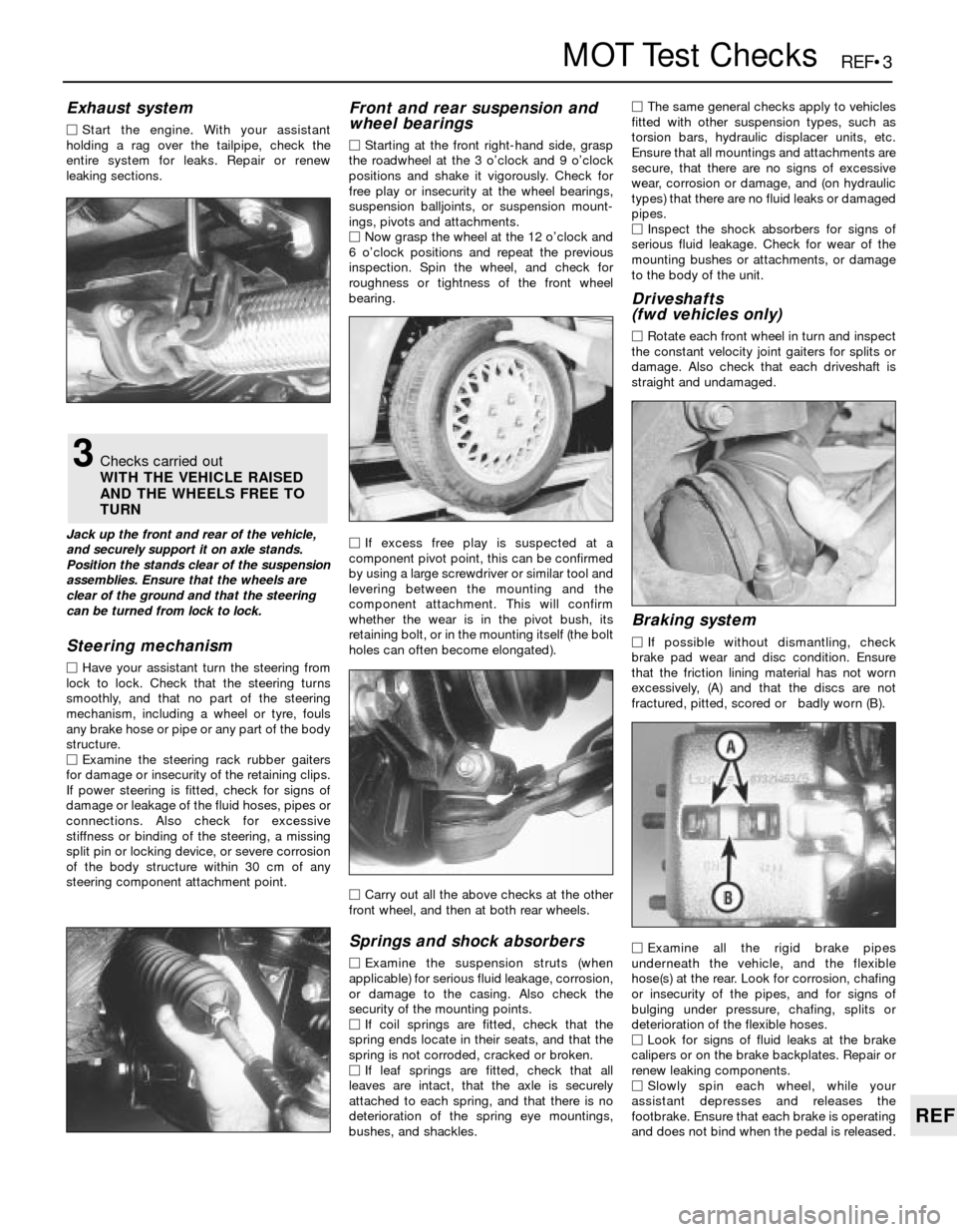
Exhaust system
MStart the engine. With your assistant
holding a rag over the tailpipe, check the
entire system for leaks. Repair or renew
leaking sections.
Jack up the front and rear of the vehicle,
and securely support it on axle stands.
Position the stands clear of the suspension
assemblies. Ensure that the wheels are
clear of the ground and that the steering
can be turned from lock to lock.
Steering mechanism
MHave your assistant turn the steering from
lock to lock. Check that the steering turns
smoothly, and that no part of the steering
mechanism, including a wheel or tyre, fouls
any brake hose or pipe or any part of the body
structure.
MExamine the steering rack rubber gaiters
for damage or insecurity of the retaining clips.
If power steering is fitted, check for signs of
damage or leakage of the fluid hoses, pipes or
connections. Also check for excessive
stiffness or binding of the steering, a missing
split pin or locking device, or severe corrosion
of the body structure within 30 cm of any
steering component attachment point.
Front and rear suspension and
wheel bearings
MStarting at the front right-hand side, grasp
the roadwheel at the 3 o’clock and 9 o’clock
positions and shake it vigorously. Check for
free play or insecurity at the wheel bearings,
suspension balljoints, or suspension mount-
ings, pivots and attachments.
MNow grasp the wheel at the 12 o’clock and
6 o’clock positions and repeat the previous
inspection. Spin the wheel, and check for
roughness or tightness of the front wheel
bearing.
MIf excess free play is suspected at a
component pivot point, this can be confirmed
by using a large screwdriver or similar tool and
levering between the mounting and the
component attachment. This will confirm
whether the wear is in the pivot bush, its
retaining bolt, or in the mounting itself (the bolt
holes can often become elongated).
MCarry out all the above checks at the other
front wheel, and then at both rear wheels.
Springs and shock absorbers
MExamine the suspension struts (when
applicable) for serious fluid leakage, corrosion,
or damage to the casing. Also check the
security of the mounting points.
MIf coil springs are fitted, check that the
spring ends locate in their seats, and that the
spring is not corroded, cracked or broken.
MIf leaf springs are fitted, check that all
leaves are intact, that the axle is securely
attached to each spring, and that there is no
deterioration of the spring eye mountings,
bushes, and shackles.MThe same general checks apply to vehicles
fitted with other suspension types, such as
torsion bars, hydraulic displacer units, etc.
Ensure that all mountings and attachments are
secure, that there are no signs of excessive
wear, corrosion or damage, and (on hydraulic
types) that there are no fluid leaks or damaged
pipes.
MInspect the shock absorbers for signs of
serious fluid leakage. Check for wear of the
mounting bushes or attachments, or damage
to the body of the unit.
Driveshafts
(fwd vehicles only)
MRotate each front wheel in turn and inspect
the constant velocity joint gaiters for splits or
damage. Also check that each driveshaft is
straight and undamaged.
Braking system
MIf possible without dismantling, check
brake pad wear and disc condition. Ensure
that the friction lining material has not worn
excessively, (A) and that the discs are not
fractured, pitted, scored or badly worn (B).
MExamine all the rigid brake pipes
underneath the vehicle, and the flexible
hose(s) at the rear. Look for corrosion, chafing
or insecurity of the pipes, and for signs of
bulging under pressure, chafing, splits or
deterioration of the flexible hoses.
MLook for signs of fluid leaks at the brake
calipers or on the brake backplates. Repair or
renew leaking components.
MSlowly spin each wheel, while your
assistant depresses and releases the
footbrake. Ensure that each brake is operating
and does not bind when the pedal is released.
3Checks carried out
WITH THE VEHICLE RAISED
AND THE WHEELS FREE TO
TURN
Page 213 of 228
REF•12Fault Finding
Fuel system
Excessive fuel consumption
m mDirty or clogged air filter element (Chapter 1).
m mIgnition timing incorrect (Chapter 5).
m mEmissions system not functioning properly (Chapter 6).
m mFuel injection internal parts or carburettor jets excessively worn or
damaged (Chapter 4).
m mLow tyre pressure or incorrect tyre size (Chapter 1).
m mUnsympathetic driving style, or unfavourable conditions.
Fuel leakage and/or fuel odour
Warning: Don’t drive the vehicle if a fuel leak is
suspected. Leaking fuel in the engine compartment
could catch fire.
m mLeak in a fuel feed or vent line (Chapter 4).
m mTank overfilled.
m mFuel injector or carburettor parts excessively worn, or fuel system
gaskets leaking (Chapter 4).
Cooling system
Overheating
m mInsufficient coolant in system (Chapter 1).
m mWater pump drivebelt defective or out of adjustment (Chapter 1).
m mRadiator matrix blocked, or grille restricted (Chapter 3).
m mThermostat faulty (Chapter 3).
m mRadiator cap not maintaining proper pressure (Chapter 3).
m mIgnition timing incorrect (Chapter 5).
Overcooling
m
mFaulty thermostat (Chapter 3).
External coolant leakage
m
mDeteriorated/damaged hoses; loose clamps (Chapters 1 and 3).
m mWater pump seal defective (Chapters 1 and 3).
m mLeakage from radiator matrix, heater matrix or header tank
(Chapter 3).
m mRadiator/engine block drain plugs or water jacket core plugs
leaking (Chapters 2 and 3).
Internal coolant leakage
m mLeaking cylinder head gasket (Chapter 2).
m mCracked cylinder bore or cylinder head (Chapter 2).
Coolant loss
m
mToo much coolant in system (Chapter 1).
m mCoolant boiling away because of overheating (see above).
m mInternal or external leakage (see above).
m mFaulty radiator cap (Chapter 3).
Poor coolant circulation
m
mInoperative water pump (Chapter 3).
m mRestriction in cooling system (Chapters 1 and 3).
m mWater pump drivebelt defective/out of adjustment (Chapter 1).
m mThermostat sticking (Chapter 3).
Clutch
Pedal travels to floor - no pressure or very little
resistance
m mMaster or slave cylinder faulty (Chapter 8).
m mFluid line burst or leaking (Chapter 8).
m mConnections leaking (Chapter 8).
m mNo fluid in reservoir (Chapter 1).
m mIf fluid is present in master cylinder dust cover, master cylinder rear
seal has failed (Chapter 8).
m mBroken release bearing or fork (Chapter 8).
Fluid in area of master cylinder dust cover, and on
pedal
m mRear seal failure in master cylinder (Chapter 8).
Fluid on slave cylinder
m
mSlave cylinder plunger seal faulty (Chapter 8).
Pedal feels “spongy” when depressed
m
mAir in system (Chapter 8).
Unable to select gears
m
mFaulty transmission (Chapter 7).
m mFaulty clutch plate (Chapter 8).
m mFork and bearing not assembled properly (Chapter 8).
m mFaulty pressure plate (Chapter 8).
m mPressure plate-to-flywheel bolts loose (Chapter 8).
Clutch slips (engine speed increases with no
increase in vehicle speed)
m mClutch plate worn (Chapter 8).
m mClutch plate is oil-soaked by leaking rear main seal (Chapter 8).
m mWarped pressure plate or flywheel (Chapter 8).
m mWeak diaphragm spring (Chapter 8).
m mClutch plate overheated.
Grabbing (chattering) as clutch is engaged
m
mOil on clutch plate lining, burned or glazed facings (Chapter 8).
m mWorn or loose engine or transmission mountings (Chapters 2
and 7A).
m mWorn splines on clutch plate hub (Chapter 8).
m mWarped pressure plate or flywheel (Chapter 8).
Noise in clutch area
m
mFork improperly fitted (Chapter 8).
m mFaulty release bearing (Chapter 8).
Clutch pedal stays on floor
m
mFork binding in housing (Chapter 8).
m mBroken release bearing or fork (Chapter 8).
High pedal effort
m
mFork binding in housing (Chapter 8).
m mPressure plate faulty (Chapter 8).
m mIncorrect-size master or slave cylinder fitted (Chapter 8).
Page 215 of 228
REF•14Fault Finding
Brakes
Note:Before assuming that a brake problem exists, make sure that:
a) The tyres are in good condition and properly inflated (Chapter 1).
b) The wheel alignment (tracking) is correct (Chapter 10).
c) The vehicle is not loaded with weight in an unequal manner.
Vehicle pulls to one side during braking
m mIncorrect tyre pressures (Chapter 1).
m mWheel alignment (tracking) incorrect (Chapter 10)
m mUnmatched tyres on same axle.
m mRestricted brake lines or hoses (Chapter 9).
m mMalfunctioning caliper assembly (Chapter 9).
m mLoose suspension parts (Chapter 10).
m mLoose calipers (Chapter 9).
Noise (high-pitched squeal) when the brakes are
applied
m mFront and/or rear disc brake pads worn out. The noise comes from
the wear sensor rubbing against the disc. Renew the pads
immediately (Chapter 9).
Brake vibration (pedal pulsates)
Note:If the vehicle has ABS, it is normal for the brake pedal to pulsate
when the system is working.
m mExcessive lateral disc run-out (Chapter 9).
m mParallelism not within specifications (Chapter 9).
m mUneven pad wear - caused by caliper not sliding, due to improper
clearance or dirt (Chapter 9).
m mDefective disc (Chapter 9).
Excessive brake pedal travel
m
mPartial brake system failure (Chapter 9).
m mInsufficient fluid in master cylinder (Chapters 1 and 9).
m mAir trapped in system (Chapters 1 and 9).
Excessive pedal effort required to stop vehicle
m
mMalfunctioning brake servo unit (Chapter 9).
m mPartial system failure (Chapter 9).
m mExcessively-worn pads or shoes (Chapter 9).
m mCaliper piston stuck or sluggish (Chapter 9).
m mBrake pads contaminated with oil or grease (Chapter 9).
m mNew pads fitted and not yet seated. It will take a while for the new
material to seat against the disc.
Dragging brakes
m mMaster cylinder pistons not returning correctly (Chapter 9).
m mRestricted brakes lines or hoses (Chapters 1 and 9).
m mIncorrect handbrake adjustment (Chapter 9).
m mRear drum brake self-adjuster mechanism faulty (when applicable)
(Chapter 9).
Grabbing or uneven braking action
m mMalfunction of brake servo unit (Chapter 9).
m mBinding brake pedal mechanism (Chapter 9).
Brake pedal feels “spongy” when depressed
m
mAir in hydraulic lines (Chapter 9).
m mMaster cylinder mounting bolts loose (Chapter 9).
m mMaster cylinder defective (Chapter 9).
Brake pedal travels to the floor with little resistance
m
mLittle or no fluid in the master cylinder reservoir, caused by leaking
caliper piston(s), loose, damaged or disconnected brake lines
(Chapter 9).
Handbrake does not hold
m mHandbrake linkage incorrectly adjusted (Chapter 9).
m mHandbrake shoe linings worn out or contaminated (Chapter 9).
Page 216 of 228
REF•15
REF
Fault Finding
Suspension and steering
Note:Before assuming that a problem exists, check the following
items:
a) Tyre pressures and tyre condition (also check for out-of-round or
out-of-balance tyres, and bent wheel rims).
b) Steering universal joints from the column to the steering gear (for
play or wear).
c) Front and rear suspension, and the rack-and-pinion assembly (for
loose or damaged parts).
d) Wheel bearings (wheel wobble or roughness when spun).
Vehicle pulls to one side
m mMismatched or uneven tyres (Chapter 10).
m mBroken or sagging springs (Chapter 10).
m mFront wheel or rear wheel alignment incorrect (Chapter 10).
m mFront brake problem (Chapter 9).
Abnormal or excessive tyre wear
m
mFront wheel or rear wheel alignment incorrect (Chapter 10).
m mSagging or broken springs (Chapter 10).
m mTyre out of balance (Chapter 10).
m mWorn shock absorber (Chapter 10).
m mOverloaded vehicle or unsympathetic driving style.
m mTyres not rotated regularly.
Wheel makes a “thumping” noise
m
mBlister or bump on tyre (Chapter 10).
m mFaulty shock absorber action (Chapter 10).
m mWheel bolts loose.
Shimmy, shake or vibration
m
mTyre or wheel out of balance or out of round (Chapter 10).
m mLoose, worn or incorrectly-adjusted wheel bearings (Chapter 1).
m mWorn tie-rod ends (Chapter 10).
m mWorn balljoints (Chapter 10).
m mExcessive wheel run-out (Chapter 10).
m mBlister or bump on tyre (Chapter 10).
m mWheel bolts loose.
High steering effort
m
mLack of lubrication at balljoints, tie-rod ends and steering gear
(Chapter 1).
m mIncorrect front wheel alignment (Chapter 10).
m mLow tyre pressure(s) (Chapter 1).
m mPower steering fluid low, or steering pump drivebelt slipping,
where applicable (Chapter 10)
Poor steering self-centring
m mLack of lubrication at balljoints and tie-rod ends (Chapter 1).
m mBinding in balljoints (Chapter 10).
m mBinding in steering column (Chapter 10).
m mLack of lubricant in steering gear (Chapter 10).
m mInaccurate front wheel alignment (Chapter 10).
Abnormal noise at the front end
m
mLack of lubrication at balljoints and tie-rod ends (Chapter 1).
m mDamaged shock absorber mounting (Chapter 10).
m mWorn control arm bushings or tie-rod ends (Chapter 10).
m mLoose anti-roll bar (Chapter 10).
m mLoose wheel bolts.
m mLoose suspension mounting bolts (Chapter 10).
Wandering or poor steering stability
m
mMismatched or uneven tyres (Chapter 10).
m mLack of lubrication at balljoints and tie-rod ends (Chapter 1).
m mWorn shock absorbers (Chapter 10).
m mLoose anti-roll bar (Chapter 10).
m mBroken or sagging springs (Chapter 10).
m mFront or rear wheel alignment incorrect (Chapter 10).
Erratic steering when braking
m
mWheel bearings worn (Chapter 1).
m mBroken or sagging springs (Chapter 10).
m mLeaking wheel cylinder (rear drum brake models) or caliper
(Chapter 9).
m mWarped discs (Chapter 9).
Excessive pitching and/or rolling around corners or
during braking
m mLoose anti-roll bar (Chapter 10).
m mWorn shock absorbers or mountings (Chapter 10).
m mBroken or sagging springs (Chapter 10).
m mOverloaded vehicle.
Suspension bottoms
m
mOverloaded vehicle.
m mWorn shock absorbers (Chapter 10).
m mBroken or sagging springs, or incorrect springs fitted (Chapter 10).
Unevenly-worn tyres
m
mFront wheel or rear wheel alignment incorrect (Chapter 10).
m mWorn shock absorbers (Chapter 10).
m mWheel bearings worn (Chapter 10).
m mExcessive tyre or wheel run-out (Chapter 10).
m mWorn balljoints (Chapter 10).
Excessive tyre wear on outside edge
m
mTyre pressures incorrect (Chapter 1).
m mExcessive cornering speed.
m mWheel alignment incorrect (excessive toe-in) (Chapter 10).
m mSuspension components damaged (Chapter 10).
Excessive tyre wear on inside edge
m
mTyre pressures incorrect (Chapter 1).
m mWheel alignment incorrect (excessive toe-out) (Chapter 10).
m mLoose or damaged steering components (Chapter 10).
Tyre tread worn in one place
m
mTyres out of balance.
m mDamaged or buckled wheel. Inspect and renew if necessary.
m mDefective tyre (Chapter 1).
Excessive play or looseness in steering system
m
mWheel bearing(s) worn (Chapter 10.
m mTie-rod end loose or worn (Chapter 10).
m mSteering gear mountings loose (Chapter 10).
Rattling or clicking noise in steering gear
m
mInsufficient or incorrect lubricant in rack-and-pinion assembly
(Chapter 10).
m mSteering gear mountings loose (Chapter 10).
Page 221 of 228
REF•21
REF
Glossary of Technical Terms
CamshaftA rotating shaft on which a series
of cam lobes operate the valve mechanisms.
The camshaft may be driven by gears, by
sprockets and chain or by sprockets and a
belt.
CanisterA container in an evaporative
emission control system; contains activated
charcoal granules to trap vapours from the
fuel system.
CarburettorA device which mixes fuel with
air in the proper proportions to provide a
desired power output from a spark ignition
internal combustion engine.
CastellatedResembling the parapets along
the top of a castle wall. For example, a
castellated balljoint stud nut.
CastorIn wheel alignment, the backward or
forward tilt of the steering axis. Castor is
positive when the steering axis is inclined
rearward at the top.Catalytic converterA silencer-like device in
the exhaust system which converts certain
pollutants in the exhaust gases into less
harmful substances.
CirclipA ring-shaped clip used to prevent
endwise movement of cylindrical parts and
shafts. An internal circlip is installed in a
groove in a housing; an external circlip fits into
a groove on the outside of a cylindrical piece
such as a shaft.
ClearanceThe amount of space between
two parts. For example, between a piston and
a cylinder, between a bearing and a journal,
etc.
Coil springA spiral of elastic steel found in
various sizes throughout a vehicle, for
example as a springing medium in the
suspension and in the valve train.
CompressionReduction in volume, and
increase in pressure and temperature, of a
gas, caused by squeezing it into a smaller
space.
Compression ratioThe relationship between
cylinder volume when the piston is at top
dead centre and cylinder volume when the
piston is at bottom dead centre.
Constant velocity (CV) jointA type of
universal joint that cancels out vibrations
caused by driving power being transmitted
through an angle.
Core plugA disc or cup-shaped metal device
inserted in a hole in a casting through which
core was removed when the casting was
formed. Also known as a freeze plug or
expansion plug.
CrankcaseThe lower part of the engine
block in which the crankshaft rotates.
CrankshaftThe main rotating member, or
shaft, running the length of the crankcase,
with offset “throws” to which the connecting
rods are attached.Crocodile clipSee Alligator clip
DDiagnostic codeCode numbers obtained by
accessing the diagnostic mode of an engine
management computer. This code can be
used to determine the area in the system
where a malfunction may be located.
Disc brakeA brake design incorporating a
rotating disc onto which brake pads are
squeezed. The resulting friction converts the
energy of a moving vehicle into heat.
Double-overhead cam (DOHC)An engine
that uses two overhead camshafts, usually
one for the intake valves and one for the
exhaust valves.
Drivebelt(s)The belt(s) used to drive
accessories such as the alternator, water
pump, power steering pump, air conditioning
compressor, etc. off the crankshaft pulley.
DriveshaftAny shaft used to transmit
motion. Commonly used when referring to the
axleshafts on a front wheel drive vehicle.
Drum brakeA type of brake using a drum-
shaped metal cylinder attached to the inner
surface of the wheel. When the brake pedal is
pressed, curved brake shoes with friction
linings press against the inside of the drum to
slow or stop the vehicle.
Castellated nut
Catalytic converter
Crankshaft assembly
Carburettor
Canister
Drum brake assembly
Accessory drivebelts
Driveshaft