Rear BMW 3 SERIES 1989 E30 Repair Manual
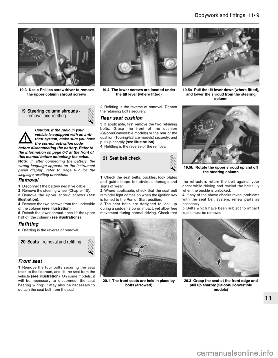
[x] Cancel search | Manufacturer: BMW, Model Year: 1989, Model line: 3 SERIES, Model: BMW 3 SERIES 1989 E30Pages: 228, PDF Size: 7.04 MB
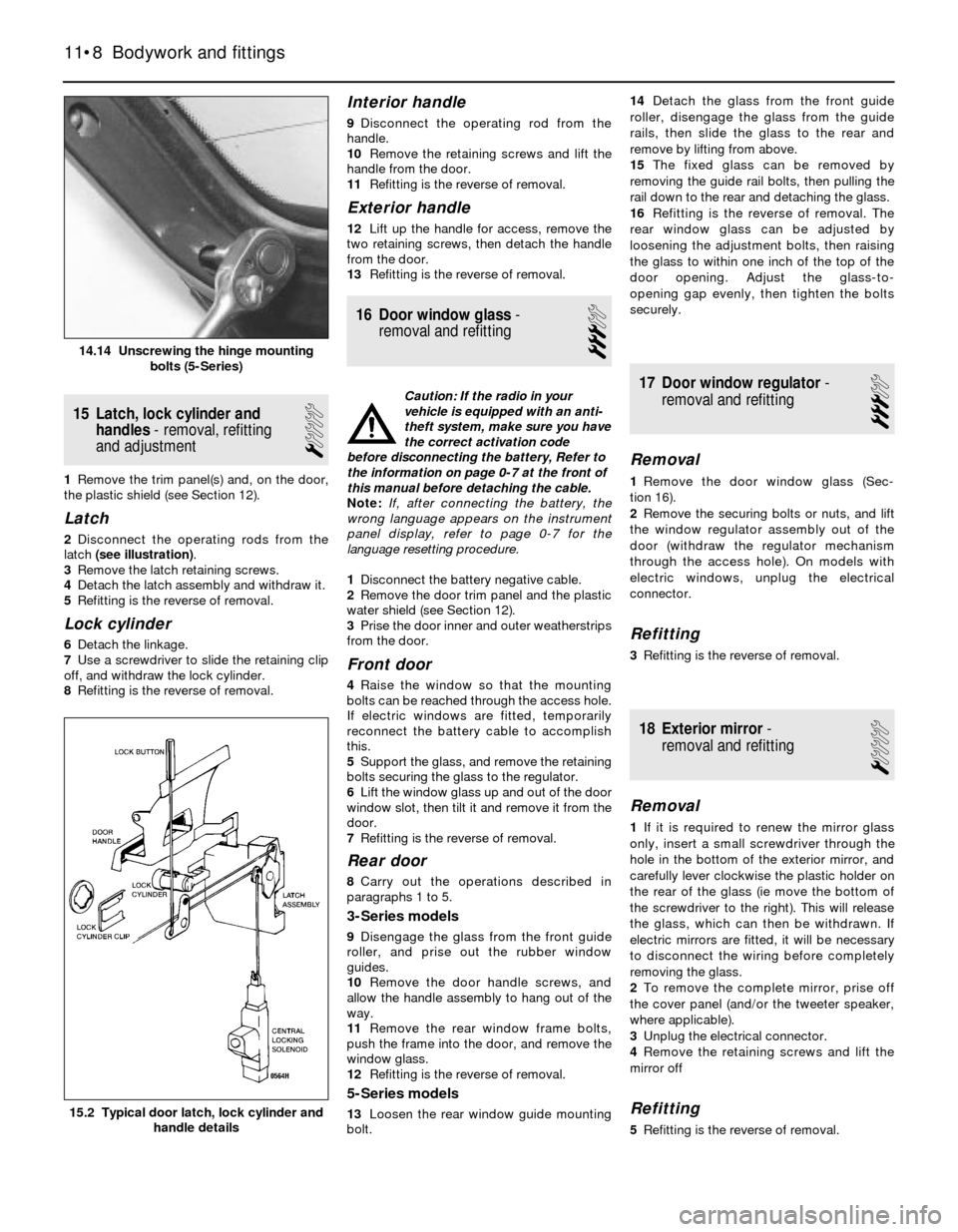
Page 156 of 228
syringe or hand pump, empty the power
steering fluid reservoir.
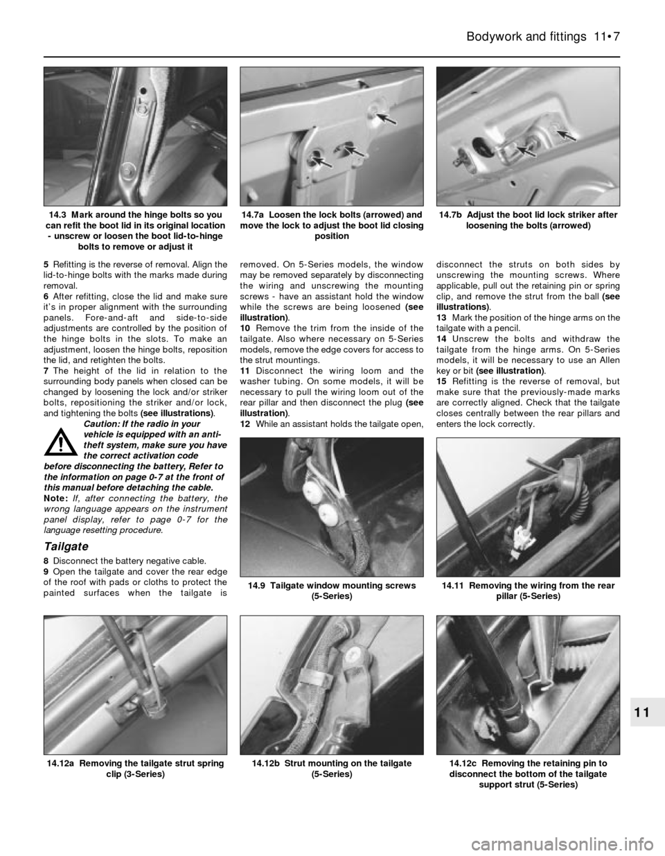
4On power steering models, remove the
banjo bolts and disconnect the power
steering pressure and return lines from the
steering gear. Place a container under the
lines to catch spilled fluid. Plug the lines to
prevent excessive fluid loss and
contamination. Discard the sealing washers
(new ones should be used when
reassembling).
5Disconnect the track rod ends from the
steering arms (see Section 17).
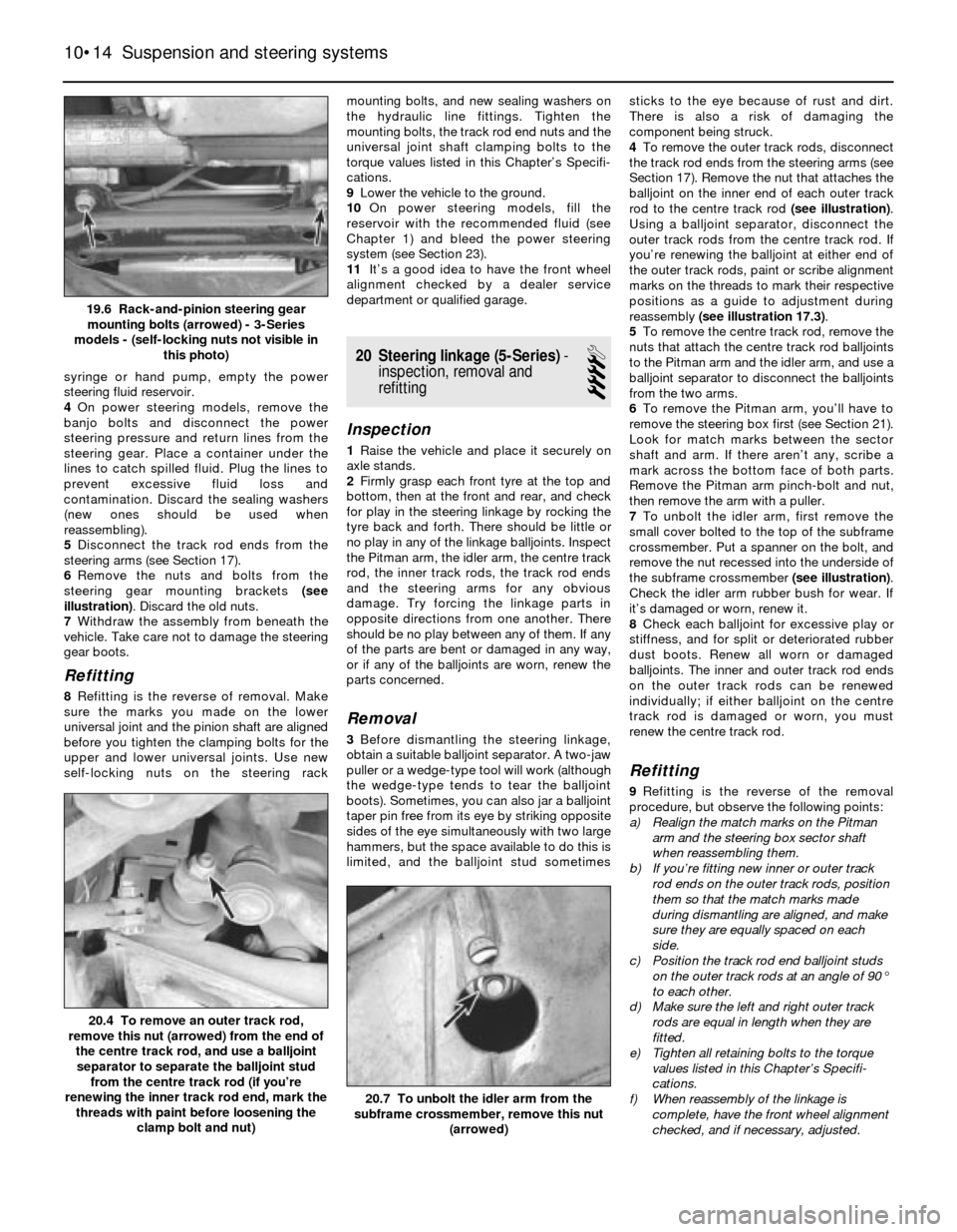
6Remove the nuts and bolts from the
steering gear mounting brackets (see
illustration). Discard the old nuts.
7Withdraw the assembly from beneath the
vehicle. Take care not to damage the steering
gear boots.
Refitting
8Refitting is the reverse of removal. Make
sure the marks you made on the lower
universal joint and the pinion shaft are aligned
before you tighten the clamping bolts for the
upper and lower universal joints. Use new
self-locking nuts on the steering rackmounting bolts, and new sealing washers on
the hydraulic line fittings. Tighten the
mounting bolts, the track rod end nuts and the
universal joint shaft clamping bolts to the
torque values listed in this Chapter’s Specifi-
cations.
9Lower the vehicle to the ground.
10On power steering models, fill the
reservoir with the recommended fluid (see
Chapter 1) and bleed the power steering
system (see Section 23).
11It’s a good idea to have the front wheel
alignment checked by a dealer service
department or qualified garage.
20 Steering linkage (5-Series)-
inspection, removal and
refitting
4
Inspection
1Raise the vehicle and place it securely on
axle stands.
2Firmly grasp each front tyre at the top and
bottom, then at the front and rear, and check
for play in the steering linkage by rocking the
tyre back and forth. There should be little or
no play in any of the linkage balljoints. Inspect
the Pitman arm, the idler arm, the centre track
rod, the inner track rods, the track rod ends
and the steering arms for any obvious
damage. Try forcing the linkage parts in
opposite directions from one another. There
should be no play between any of them. If any
of the parts are bent or damaged in any way,
or if any of the balljoints are worn, renew the
parts concerned.
Removal
3Before dismantling the steering linkage,
obtain a suitable balljoint separator. A two-jaw
puller or a wedge-type tool will work (although
the wedge-type tends to tear the balljoint
boots). Sometimes, you can also jar a balljoint
taper pin free from its eye by striking opposite
sides of the eye simultaneously with two large
hammers, but the space available to do this is
limited, and the balljoint stud sometimessticks to the eye because of rust and dirt.
There is also a risk of damaging the
component being struck.
4To remove the outer track rods, disconnect
the track rod ends from the steering arms (see
Section 17). Remove the nut that attaches the
balljoint on the inner end of each outer track
rod to the centre track rod (see illustration).
Using a balljoint separator, disconnect the
outer track rods from the centre track rod. If
you’re renewing the balljoint at either end of
the outer track rods, paint or scribe alignment
marks on the threads to mark their respective
positions as a guide to adjustment during
reassembly (see illustration 17.3).
5To remove the centre track rod, remove the
nuts that attach the centre track rod balljoints
to the Pitman arm and the idler arm, and use a
balljoint separator to disconnect the balljoints
from the two arms.
6To remove the Pitman arm, you’ll have to
remove the steering box first (see Section 21).
Look for match marks between the sector
shaft and arm. If there aren’t any, scribe a
mark across the bottom face of both parts.
Remove the Pitman arm pinch-bolt and nut,
then remove the arm with a puller.
7To unbolt the idler arm, first remove the
small cover bolted to the top of the subframe
crossmember. Put a spanner on the bolt, and
remove the nut recessed into the underside of
the subframe crossmember (see illustration).
Check the idler arm rubber bush for wear. If
it’s damaged or worn, renew it.
8Check each balljoint for excessive play or
stiffness, and for split or deteriorated rubber
dust boots. Renew all worn or damaged
balljoints. The inner and outer track rod ends
on the outer track rods can be renewed
individually; if either balljoint on the centre
track rod is damaged or worn, you must
renew the centre track rod.
Refitting
9Refitting is the reverse of the removal
procedure, but observe the following points:
a) Realign the match marks on the Pitman
arm and the steering box sector shaft
when reassembling them.
b) If you’re fitting new inner or outer track
rod ends on the outer track rods, position
them so that the match marks made
during dismantling are aligned, and make
sure they are equally spaced on each
side.
c) Position the track rod end balljoint studs
on the outer track rods at an angle of 90°
to each other.
d) Make sure the left and right outer track
rods are equal in length when they are
fitted.
e) Tighten all retaining bolts to the torque
values listed in this Chapter’s Specifi-
cations.
f) When reassembly of the linkage is
complete, have the front wheel alignment
checked, and if necessary, adjusted.
10•14 Suspension and steering systems
20.7 To unbolt the idler arm from the
subframe crossmember, remove this nut
(arrowed)
20.4 To remove an outer track rod,
remove this nut (arrowed) from the end of
the centre track rod, and use a balljoint
separator to separate the balljoint stud
from the centre track rod (if you’re
renewing the inner track rod end, mark the
threads with paint before loosening the
clamp bolt and nut)
19.6 Rack-and-pinion steering gear
mounting bolts (arrowed) - 3-Series
models - (self-locking nuts not visible in
this photo)
Page 159 of 228
26 Wheel alignment-
general information
4
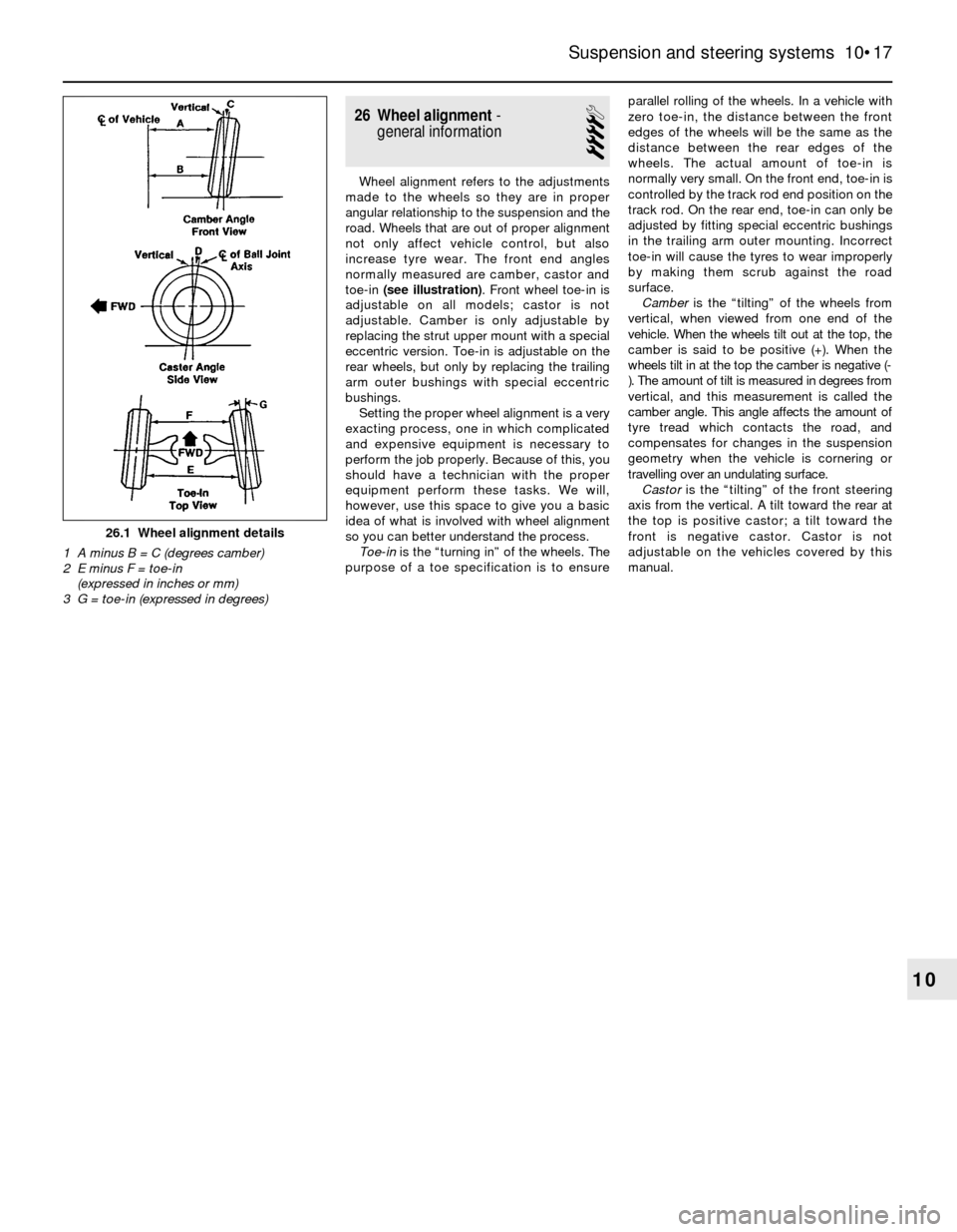
Wheel alignment refers to the adjustments
made to the wheels so they are in proper
angular relationship to the suspension and the
road. Wheels that are out of proper alignment
not only affect vehicle control, but also
increase tyre wear. The front end angles
normally measured are camber, castor and
toe-in (see illustration). Front wheel toe-in is
adjustable on all models; castor is not
adjustable. Camber is only adjustable by
replacing the strut upper mount with a special
eccentric version. Toe-in is adjustable on the
rear wheels, but only by replacing the trailing
arm outer bushings with special eccentric
bushings.
Setting the proper wheel alignment is a very
exacting process, one in which complicated
and expensive equipment is necessary to
perform the job properly. Because of this, you
should have a technician with the proper
equipment perform these tasks. We will,
however, use this space to give you a basic
idea of what is involved with wheel alignment
so you can better understand the process.
Toe-inis the “turning in” of the wheels. The
purpose of a toe specification is to ensureparallel rolling of the wheels. In a vehicle with
zero toe-in, the distance between the front
edges of the wheels will be the same as the
distance between the rear edges of the
wheels. The actual amount of toe-in is
normally very small. On the front end, toe-in is
controlled by the track rod end position on the
track rod. On the rear end, toe-in can only be
adjusted by fitting special eccentric bushings
in the trailing arm outer mounting. Incorrect
toe-in will cause the tyres to wear improperly
by making them scrub against the road
surface.
Camberis the “tilting” of the wheels from
vertical, when viewed from one end of the
vehicle. When the wheels tilt out at the top, the
camber is said to be positive (+). When the
wheels tilt in at the top the camber is negative (-
). The amount of tilt is measured in degrees from
vertical, and this measurement is called the
camber angle. This angle affects the amount of
tyre tread which contacts the road, and
compensates for changes in the suspension
geometry when the vehicle is cornering or
travelling over an undulating surface.
Castoris the “tilting” of the front steering
axis from the vertical. A tilt toward the rear at
the top is positive castor; a tilt toward the
front is negative castor. Castor is not
adjustable on the vehicles covered by this
manual.
Suspension and steering systems 10•17
10
26.1 Wheel alignment details
1 A minus B = C (degrees camber)
2 E minus F = toe-in
(expressed in inches or mm)
3 G = toe-in (expressed in degrees)
Page 160 of 228
11
1 General information
These models feature an all-steel welded
construction, where the floorpan and body
components are welded together and
attached to separate front and rear subframe
assemblies. Certain components are
particularly vulnerable to accident damage,
and can be unbolted and repaired or renewed.
Among these parts are the body mouldings,
bumpers, bonnet, doors, tailgate, and all
glass.
Only general body maintenance procedures
and body panel repair procedures within the
scope of the do-it-yourselfer are included in
this Chapter.
2 Bodywork and underframe-
maintenance
1
The general condition of a vehicle’s
bodywork is the one thing that significantly
affects its value. Maintenance is easy, but
needs to be regular. Neglect, particularly after
minor damage, can lead quickly to further
deterioration and costly repair bills. It is
important also to keep watch on those parts
of the vehicle not immediately visible, for
instance the underside, inside all the wheelarches, and the lower part of the engine
compartment.
The basic maintenance routine for the
bodywork is washing - preferably with a lot of
water, from a hose. This will remove all the
loose solids which may have stuck to the
vehicle. It is important to flush these off in
such a way as to prevent grit from scratching
the finish. The wheel arches and underframe
need washing in the same way, to remove any
accumulated mud, which will retain moisture
and tend to encourage rust. Paradoxically
enough, the best time to clean the underframe
and wheel arches is in wet weather, when the
mud is thoroughly wet and soft. In very wet
weather, the underframe is usually cleaned of
large accumulations automatically, and this is
a good time for inspection.
Periodically, except on vehicles with a wax-
based underbody protective coating, it is a
good idea to have the whole of the
underframe of the vehicle steam-cleaned,
engine compartment included, so that a
thorough inspection can be carried out to see
what minor repairs and renovations are
necessary. Steam-cleaning is available at
many garages, and is necessary for the
removal of the accumulation of oily grime,
which sometimes is allowed to become thick
in certain areas. If steam-cleaning facilities are
not available, there are some excellent grease
solvents available which can be brush-
applied; the dirt can then be simply hosed off.
Note that these methods should not be usedon vehicles with wax-based underbody
protective coating, or the coating will be
removed. Such vehicles should be inspected
annually, preferably just prior to Winter, when
the underbody should be washed down, and
any damage to the wax coating repaired.
Ideally, a completely fresh coat should be
applied. It would also be worth considering
the use of such wax-based protection for
injection into door panels, sills, box sections,
etc, as an additional safeguard against rust
damage, where such protection is not
provided by the vehicle manufacturer.
After washing paintwork, wipe off with a
chamois leather to give an unspotted clear
finish. A coat of clear protective wax polish will
give added protection against chemical
pollutants in the air. If the paintwork sheen has
dulled or oxidised, use a cleaner/polisher
combination to restore the brilliance of the
shine. This requires a little effort, but such
dulling is usually caused because regular
washing has been neglected. Care needs to be
taken with metallic paintwork, as special non-
abrasive cleaner/polisher is required to avoid
damage to the finish. Always check that the
door and ventilator opening drain holes and
pipes are completely clear, so that water can
be drained out. Brightwork should be treated in
the same way as paintwork. Windscreens and
windows can be kept clear of the smeary film
which often appears, by the use of proprietary
glass cleaner. Never use any form of wax or
other body or chromium polish on glass.
Chapter 11 Bodywork and fittings
Bodywork and underframe - maintenance . . . . . . . . . . . . . . . . . . . . 2
Bodywork repair - major damage . . . . . . . . . . . . . . . . . . . . . . . . . . . 6
Bodywork repair - minor damage . . . . . . . . . . . . . . . . . . . . . . . . . . . 5
Bonnet - removal, refitting and adjustment . . . . . . . . . . . . . . . . . . . . 10
Boot lid/tailgate - removal, refitting and adjustment . . . . . . . . . . . . . 14
Bumpers - removal and refitting . . . . . . . . . . . . . . . . . . . . . . . . . . . . 11
Door - removal, refitting and adjustment . . . . . . . . . . . . . . . . . . . . . 13
Door trim panel - removal and refitting . . . . . . . . . . . . . . . . . . . . . . . 12
Door window glass - removal and refitting . . . . . . . . . . . . . . . . . . . . 16
Door window regulator - removal and refitting . . . . . . . . . . . . . . . . . 17
Exterior mirror - removal and refitting . . . . . . . . . . . . . . . . . . . . . . . . 18Fixed glass - renewal . . . . . . . . . . . . . . . . . . . . . . . . . . . . . . . . . . . . 8
General information . . . . . . . . . . . . . . . . . . . . . . . . . . . . . . . . . . . . . . 1
Hinges and locks - maintenance . . . . . . . . . . . . . . . . . . . . . . . . . . . . 7
Interior trim - maintenance . . . . . . . . . . . . . . . . . . . . . . . . . . . . . . . . 3
Latch, lock cylinder and handles - removal, refitting and
adjustment . . . . . . . . . . . . . . . . . . . . . . . . . . . . . . . . . . . . . . . . . . . 15
Radiator grille - removal and refitting . . . . . . . . . . . . . . . . . . . . . . . . 9
Seat belt check . . . . . . . . . . . . . . . . . . . . . . . . . . . . . . . . . . . . . . . . . 21
Seats - removal and refitting . . . . . . . . . . . . . . . . . . . . . . . . . . . . . . . 20
Steering column shrouds - removal and refitting . . . . . . . . . . . . . . . 19
Upholstery and carpets - maintenance . . . . . . . . . . . . . . . . . . . . . . . 4
11•1
Easy,suitable for
novice with little
experienceFairly easy,suitable
for beginner with
some experienceFairly difficult,
suitable for competent
DIY mechanic
Difficult,suitable for
experienced DIY
mechanicVery difficult,
suitable for expert
DIY or professional
Degrees of difficulty Contents
Page 164 of 228
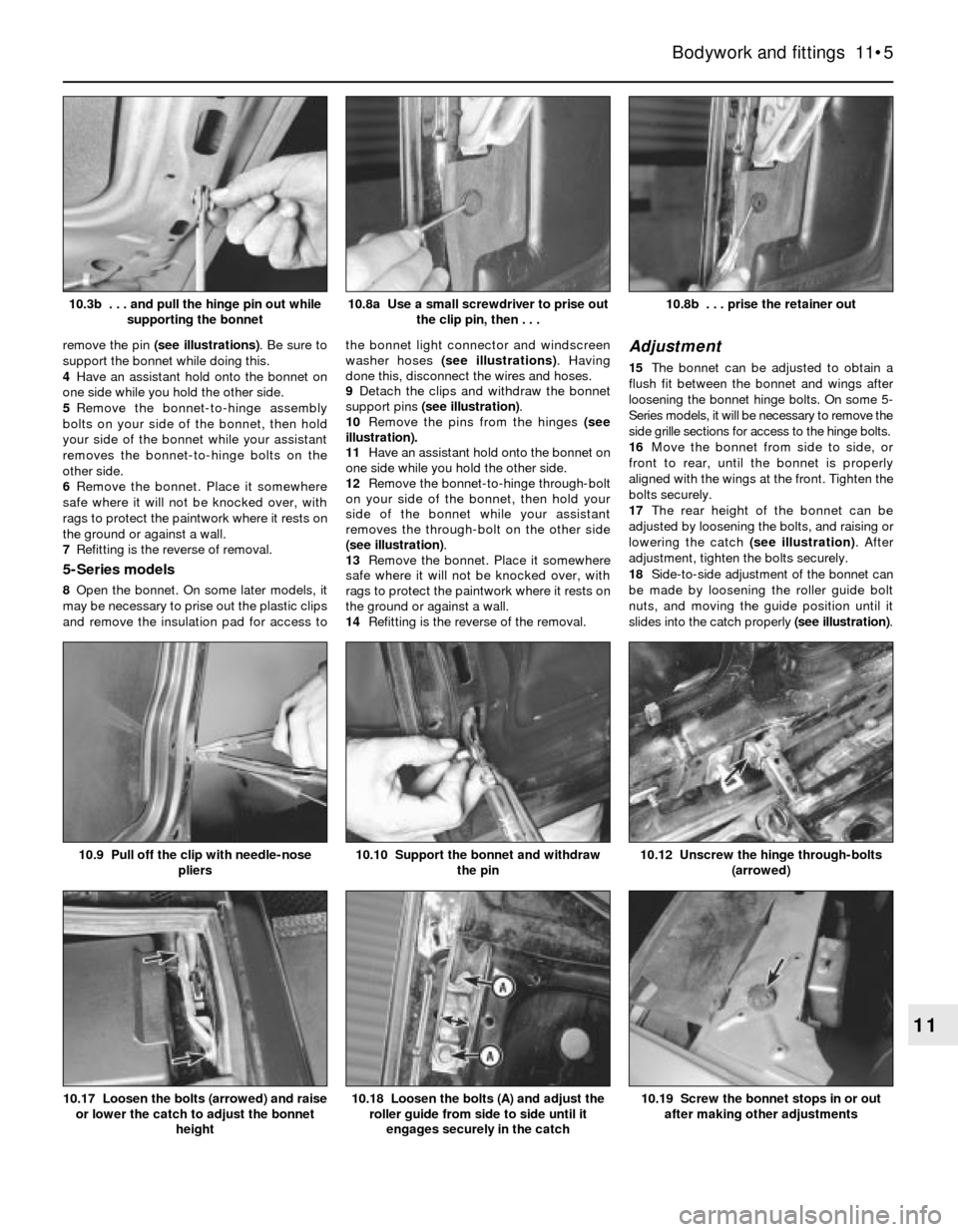
remove the pin (see illustrations). Be sure to
support the bonnet while doing this.
4Have an assistant hold onto the bonnet on
one side while you hold the other side.
5Remove the bonnet-to-hinge assembly
bolts on your side of the bonnet, then hold
your side of the bonnet while your assistant
removes the bonnet-to-hinge bolts on the
other side.
6Remove the bonnet. Place it somewhere
safe where it will not be knocked over, with
rags to protect the paintwork where it rests on
the ground or against a wall.
7Refitting is the reverse of removal.
5-Series models
8Open the bonnet. On some later models, it
may be necessary to prise out the plastic clips
and remove the insulation pad for access tothe bonnet light connector and windscreen
washer hoses (see illustrations). Having
done this, disconnect the wires and hoses.
9Detach the clips and withdraw the bonnet
support pins (see illustration).
10Remove the pins from the hinges (see
illustration).
11Have an assistant hold onto the bonnet on
one side while you hold the other side.
12Remove the bonnet-to-hinge through-bolt
on your side of the bonnet, then hold your
side of the bonnet while your assistant
removes the through-bolt on the other side
(see illustration).
13Remove the bonnet. Place it somewhere
safe where it will not be knocked over, with
rags to protect the paintwork where it rests on
the ground or against a wall.
14Refitting is the reverse of the removal.
Adjustment
15The bonnet can be adjusted to obtain a
flush fit between the bonnet and wings after
loosening the bonnet hinge bolts. On some 5-
Series models, it will be necessary to remove the
side grille sections for access to the hinge bolts.
16Move the bonnet from side to side, or
front to rear, until the bonnet is properly
aligned with the wings at the front. Tighten the
bolts securely.
17The rear height of the bonnet can be
adjusted by loosening the bolts, and raising or
lowering the catch (see illustration). After
adjustment, tighten the bolts securely.
18Side-to-side adjustment of the bonnet can
be made by loosening the roller guide bolt
nuts, and moving the guide position until it
slides into the catch properly (see illustration).
Bodywork and fittings 11•5
10.8b . . . prise the retainer out10.8a Use a small screwdriver to prise out
the clip pin, then . . .10.3b . . . and pull the hinge pin out while
supporting the bonnet
10.19 Screw the bonnet stops in or out
after making other adjustments10.18 Loosen the bolts (A) and adjust the
roller guide from side to side until it
engages securely in the catch10.17 Loosen the bolts (arrowed) and raise
or lower the catch to adjust the bonnet
height
10.12 Unscrew the hinge through-bolts
(arrowed)10.10 Support the bonnet and withdraw
the pin10.9 Pull off the clip with needle-nose
pliers
11
Page 166 of 228
5Refitting is the reverse of removal. Align the
lid-to-hinge bolts with the marks made during
removal.
6After refitting, close the lid and make sure
it’s in proper alignment with the surrounding
panels. Fore-and-aft and side-to-side
adjustments are controlled by the position of
the hinge bolts in the slots. To make an
adjustment, loosen the hinge bolts, reposition
the lid, and retighten the bolts.
7The height of the lid in relation to the
surrounding body panels when closed can be
changed by loosening the lock and/or striker
bolts, repositioning the striker and/or lock,
and tightening the bolts (see illustrations).
Caution: If the radio in your
vehicle is equipped with an anti-
theft system, make sure you have
the correct activation code
before disconnecting the battery, Refer to
the information on page 0-7 at the front of
this manual before detaching the cable.
Note: If, after connecting the battery, the
wrong language appears on the instrument
panel display, refer to page 0-7 for the
language resetting procedure.
Tailgate
8Disconnect the battery negative cable.
9Open the tailgate and cover the rear edge
of the roof with pads or cloths to protect the
painted surfaces when the tailgate isremoved. On 5-Series models, the window
may be removed separately by disconnecting
the wiring and unscrewing the mounting
screws - have an assistant hold the window
while the screws are being loosened (see
illustration).
10Remove the trim from the inside of the
tailgate. Also where necessary on 5-Series
models, remove the edge covers for access to
the strut mountings.
11Disconnect the wiring loom and the
washer tubing. On some models, it will be
necessary to pull the wiring loom out of the
rear pillar and then disconnect the plug (see
illustration).
12While an assistant holds the tailgate open,disconnect the struts on both sides by
unscrewing the mounting screws. Where
applicable, pull out the retaining pin or spring
clip, and remove the strut from the ball (see
illustrations).
13Mark the position of the hinge arms on the
tailgate with a pencil.
14Unscrew the bolts and withdraw the
tailgate from the hinge arms. On 5-Series
models, it will be necessary to use an Allen
key or bit (see illustration).
15Refitting is the reverse of removal, but
make sure that the previously-made marks
are correctly aligned. Check that the tailgate
closes centrally between the rear pillars and
enters the lock correctly.
Bodywork and fittings 11•7
14.7b Adjust the boot lid lock striker after
loosening the bolts (arrowed)14.7a Loosen the lock bolts (arrowed) and
move the lock to adjust the boot lid closing
position14.3 Mark around the hinge bolts so you
can refit the boot lid in its original location
- unscrew or loosen the boot lid-to-hinge
bolts to remove or adjust it
14.12c Removing the retaining pin to
disconnect the bottom of the tailgate
support strut (5-Series)14.12b Strut mounting on the tailgate
(5-Series)14.12a Removing the tailgate strut spring
clip (3-Series)
14.11 Removing the wiring from the rear
pillar (5-Series)14.9 Tailgate window mounting screws
(5-Series)
11
Page 167 of 228
15 Latch, lock cylinder and
handles- removal, refitting
and adjustment
1
1Remove the trim panel(s) and, on the door,
the plastic shield (see Section 12).
Latch
2Disconnect the operating rods from the
latch (see illustration).
3Remove the latch retaining screws.
4Detach the latch assembly and withdraw it.
5Refitting is the reverse of removal.
Lock cylinder
6Detach the linkage.
7Use a screwdriver to slide the retaining clip
off, and withdraw the lock cylinder.
8Refitting is the reverse of removal.
Interior handle
9Disconnect the operating rod from the
handle.
10Remove the retaining screws and lift the
handle from the door.
11Refitting is the reverse of removal.
Exterior handle
12Lift up the handle for access, remove the
two retaining screws, then detach the handle
from the door.
13Refitting is the reverse of removal.
16 Door window glass-
removal and refitting
3
Caution: If the radio in your
vehicle is equipped with an anti-
theft system, make sure you have
the correct activation code
before disconnecting the battery, Refer to
the information on page 0-7 at the front of
this manual before detaching the cable.
Note: If, after connecting the battery, the
wrong language appears on the instrument
panel display, refer to page 0-7 for the
language resetting procedure.
1Disconnect the battery negative cable.
2Remove the door trim panel and the plastic
water shield (see Section 12).
3Prise the door inner and outer weatherstrips
from the door.
Front door
4Raise the window so that the mounting
bolts can be reached through the access hole.
If electric windows are fitted, temporarily
reconnect the battery cable to accomplish
this.
5Support the glass, and remove the retaining
bolts securing the glass to the regulator.
6Lift the window glass up and out of the door
window slot, then tilt it and remove it from the
door.
7Refitting is the reverse of removal.
Rear door
8Carry out the operations described in
paragraphs 1 to 5.
3-Series models
9Disengage the glass from the front guide
roller, and prise out the rubber window
guides.
10Remove the door handle screws, and
allow the handle assembly to hang out of the
way.
11Remove the rear window frame bolts,
push the frame into the door, and remove the
window glass.
12Refitting is the reverse of removal.
5-Series models
13Loosen the rear window guide mounting
bolt.14Detach the glass from the front guide
roller, disengage the glass from the guide
rails, then slide the glass to the rear and
remove by lifting from above.
15The fixed glass can be removed by
removing the guide rail bolts, then pulling the
rail down to the rear and detaching the glass.
16Refitting is the reverse of removal. The
rear window glass can be adjusted by
loosening the adjustment bolts, then raising
the glass to within one inch of the top of the
door opening. Adjust the glass-to-
opening gap evenly, then tighten the bolts
securely.
17 Door window regulator-
removal and refitting
3
Removal
1Remove the door window glass (Sec-
tion 16).
2Remove the securing bolts or nuts, and lift
the window regulator assembly out of the
door (withdraw the regulator mechanism
through the access hole). On models with
electric windows, unplug the electrical
connector.
Refitting
3Refitting is the reverse of removal.
18 Exterior mirror-
removal and refitting
1
Removal
1If it is required to renew the mirror glass
only, insert a small screwdriver through the
hole in the bottom of the exterior mirror, and
carefully lever clockwise the plastic holder on
the rear of the glass (ie move the bottom of
the screwdriver to the right). This will release
the glass, which can then be withdrawn. If
electric mirrors are fitted, it will be necessary
to disconnect the wiring before completely
removing the glass.
2To remove the complete mirror, prise off
the cover panel (and/or the tweeter speaker,
where applicable).
3Unplug the electrical connector.
4Remove the retaining screws and lift the
mirror off
Refitting
5Refitting is the reverse of removal.
11•8 Bodywork and fittings
15.2 Typical door latch, lock cylinder and
handle details
14.14 Unscrewing the hinge mounting
bolts (5-Series)
Page 168 of 228
19 Steering column shrouds -
removal and refitting
1
Caution: If the radio in your
vehicle is equipped with an anti-
theft system, make sure you have
the correct activation code
before disconnecting the battery, Refer to
the information on page 0-7 at the front of
this manual before detaching the cable.
Note: If, after connecting the battery, the
wrong language appears on the instrument
panel display, refer to page 0-7 for the
language resetting procedure.
Removal
1Disconnect the battery negative cable.
2Remove the steering wheel (Chapter 10).
3Remove the upper shroud screws (see
illustration).
4Remove the two screws from the underside
of the column (see illustration).
5Detach the lower shroud, then lift the upper
half off the column (see illustrations).
Refitting
6Refitting is the reverse of removal.
20 Seats- removal and refitting
1
Front seat
1Remove the four bolts securing the seat
track to the floorpan, and lift the seat from the
vehicle (see illustration). On some models, it
will be necessary to disconnect the seat
heating wiring; it may also be necessary to
detach the seat belt from the seat.2Refitting is the reverse of removal. Tighten
the retaining bolts securely.
Rear seat cushion
3If applicable, first remove the two retaining
bolts. Grasp the front of the cushion
(Saloon/Convertible models) or the rear of the
cushion (Touring/Estate models) securely, and
pull up sharply (see illustration).
4Refitting is the reverse of the removal.
21 Seat belt check
1
1Check the seat belts, buckles, lock plates
and guide loops for obvious damage and
signs of wear.
2Where applicable, check that the seat belt
reminder light comes on when the ignition key
is turned to the Run or Start position.
3The seat belts are designed to lock up
during a sudden stop or impact, yet allow free
movement during normal driving. Check thatthe retractors return the belt against your
chest while driving and rewind the belt fully
when the buckle is unlocked.
4If any of the above checks reveal problems
with the seat belt system, renew parts as
necessary.
5Belts which have been subject to impact
loads must be renewed.
Bodywork and fittings 11•9
19.5a Pull the tilt lever down (where fitted),
and lower the shroud from the steering
column19.4 The lower screws are located under
the tilt lever (where fitted)19.3 Use a Phillips screwdriver to remove
the upper column shroud screws
20.3 Grasp the seat at the front edge and
pull up sharply (Saloon/Convertible
models)20.1 The front seats are held in place by
bolts (arrowed)
19.5b Rotate the upper shroud up and off
the steering column
11
Page 169 of 228
12
Chapter 12 Body electrical systems
Bulb renewal . . . . . . . . . . . . . . . . . . . . . . . . . . . . . . . . . . . . . . . . . . . 15
Central locking system - description and check . . . . . . . . . . . . . . . . 20
Cruise control system - description and check . . . . . . . . . . . . . . . . 19
Direction indicator/hazard warning flasher - check and renewal . . . 5
Electric windows - description and check . . . . . . . . . . . . . . . . . . . . 21
Electrical system fault finding - general information . . . . . . . . . . . . . 2
Fuses - general information . . . . . . . . . . . . . . . . . . . . . . . . . . . . . . . 3
General information . . . . . . . . . . . . . . . . . . . . . . . . . . . . . . . . . . . . . . 1
Headlight housing - removal and refitting . . . . . . . . . . . . . . . . . . . . . 14
Headlights - adjustment . . . . . . . . . . . . . . . . . . . . . . . . . . . . . . . . . . 13
Headlights - bulb renewal . . . . . . . . . . . . . . . . . . . . . . . . . . . . . . . . . 12Heated rear window - check and repair . . . . . . . . . . . . . . . . . . . . . . 17
Ignition switch - removal and refitting . . . . . . . . . . . . . . . . . . . . . . . . 7
Instrument cluster - removal and refitting . . . . . . . . . . . . . . . . . . . . . 10
Radio - removal and refitting . . . . . . . . . . . . . . . . . . . . . . . . . . . . . . . 8
Radio aerial - removal and refitting . . . . . . . . . . . . . . . . . . . . . . . . . . 9
Relays - general information . . . . . . . . . . . . . . . . . . . . . . . . . . . . . . . 4
Service Indicator (SI) board - general information . . . . . . . . . . . . . . 11
Steering column switches - removal and refitting . . . . . . . . . . . . . . . 6
Supplemental Restraint System (SRS) - general information . . . . . . 18
Windscreen/tailgate wiper motor - removal and refitting . . . . . . . . . 16
Wiring diagrams - general information . . . . . . . . . . . . . . . . . . . . . . . 22
12•1
Easy,suitable for
novice with little
experienceFairly easy,suitable
for beginner with
some experienceFairly difficult,
suitable for competent
DIY mechanic
Difficult,suitable for
experienced DIY
mechanicVery difficult,
suitable for expert
DIY or professional
Degrees of difficulty Contents
1 General information
The chassis electrical system of this vehicle
is of 12-volt, negative earth type. Power for
the lights and all electrical accessories is
supplied by a lead/acid-type battery, which is
charged by the alternator.
This Chapter covers repair and service
procedures for various chassis (non-engine
related) electrical components. For
information regarding the engine electrical
system components (battery, alternator,
distributor and starter motor), see Chapter 5.
Warning: To prevent electrical
short-circuits, fires and injury,
always disconnect the battery
negative terminal before
checking, repairing or renewing electrical
components.
Caution: If the radio in your
vehicle is equipped with an anti-
theft system, make sure you have
the correct activation code
before disconnecting the battery, Refer to
the information on page 0-7 at the front of
this manual before detaching the cable.
Note: If, after connecting the battery, the
wrong language appears on the instrument
panel display, refer to page 0-7 for the
language resetting procedure.
2 Electrical system fault
finding- general information
2
A typical electrical circuit consists of an
electrical component, any switches, relays,
motors, fuses, fusible links or circuit breakers,
etc related to that component, and the wiring
and connectors that link the components to
both the battery and the chassis. To help you
pinpoint an electrical circuit problem, wiring
diagrams are included at the end of this book.
Before tackling any troublesome electrical
circuit, first study the appropriate wiring
diagrams to get a complete understanding of
what makes up that individual circuit.
Troublespots, for instance, can often be
isolated by noting if other components related
to that circuit are routed through the same
fuse and earth connections.
Electrical problems usually stem from
simple causes such as loose or corroded
connectors, a blown fuse, a melted fusible
link, or a bad relay. Inspect all fuses, wires
and connectors in a problem circuit first.
The basic tools needed include a circuit
tester, a high-impedance digital voltmeter, a
continuity tester and a jumper wire with an in-
line circuit breaker for bypassing electrical
components. Before attempting to locate or
define a problem with electrical testinstruments, use the wiring diagrams to
decide where to make the necessary
connections.
Voltage checks
Perform a voltage check first when a circuit
is not functioning properly. Connect one lead
of a circuit tester to either the negative battery
terminal or a known good earth.
Connect the other lead to a connector in
the circuit being tested, preferably nearest to
the battery or fuse. If the bulb of the tester
lights up, voltage is present, which means that
the part of the circuit between the connector
and the battery is problem-free. Continue
checking the rest of the circuit in the same
fashion.
When you reach a point at which no voltage
is present, the problem lies between that point
and the last test point with voltage. Most of
the time, problems can be traced to a loose
connection.Note:Keep in mind that some
circuits receive voltage only when the ignition
key is turned to a certain position.
Electrical fault diagnosis is simple if you
keep in mind that all electrical circuits are
basically electricity running from the battery,
through the wires, switches, relays, fuses and
fusible links to each electrical component
(light bulb, motor, etc) and then to earth, from
where it is passed back to the battery. Any
electrical problem is an interruption in the flow
of electricity to and from the battery.
Page 170 of 228
Finding a short-circuit
One method of finding a short-circuit is to
remove the fuse and connect a test light or
voltmeter in its place. There should be no
voltage present in the circuit. Move the
electrical connectors from side-to-side while
watching the test light. If the bulb goes on,
there is a short to earth somewhere in that
area, probably where the insulation has been
rubbed through. The same test can be
performed on each component in a circuit,
even a switch.
Earth check
Perform a earth check to see whether a
component is properly earthed (passing
current back via the vehicle body). Disconnect
the battery, and connect one lead of a self-
powered test light (often known as a
continuity tester) to a known good earth.
Connect the other lead to the wire or earth
connection being tested. The bulb should
light, indicating a good earth connection. If
not, dismantle the connection, and clean all
relevant parts thoroughly. When re-making
the connection, use serrated (shakeproof)
washers if possible, and tighten all bolts, etc,
securely.
Caution: If the radio in your
vehicle is equipped with an anti-
theft system, make sure you have
the correct activation code
before disconnecting the battery, Refer to
the information on page 0-7 at the front of
this manual before detaching the cable.
Note: If, after connecting the battery, the
wrong language appears on the instrument
panel display, refer to page 0-7 for the
language resetting procedure.
Continuity check
A continuity check determines if there are
any breaks in a circuit - if it is conducting
electricity properly. With the circuit off (no
power in the circuit), a self-powered continuity
tester can be used to check the circuit.
Connect the test leads to both ends of the
circuit, and if the test light comes on, the
circuit is passing current properly. If the light
doesn’t come on, there is a break somewhere
in the circuit. The same procedure can be
used to test a switch, by connecting the
continuity tester to the power-in and power-
out sides of the switch. With the switch turned
on, the test light should come on.
Finding an open-circuit
When diagnosing for possible open-
circuits, it is often difficult to locate them by
sight, because oxidation or terminal
misalignment are hidden by the connectors.
Intermittent problems are often caused by
oxidised or loose connections. Merely
wiggling an electrical connector may correct
the open-circuit condition, albeit temporarily.
Dismantle the connector, and spray with a
water-dispersant aerosol. On simpler
connectors, it may be possible to carefullybend the connector pins inside, to improve
the metal-to-metal contact - don’t damage
the connector in the process, however.
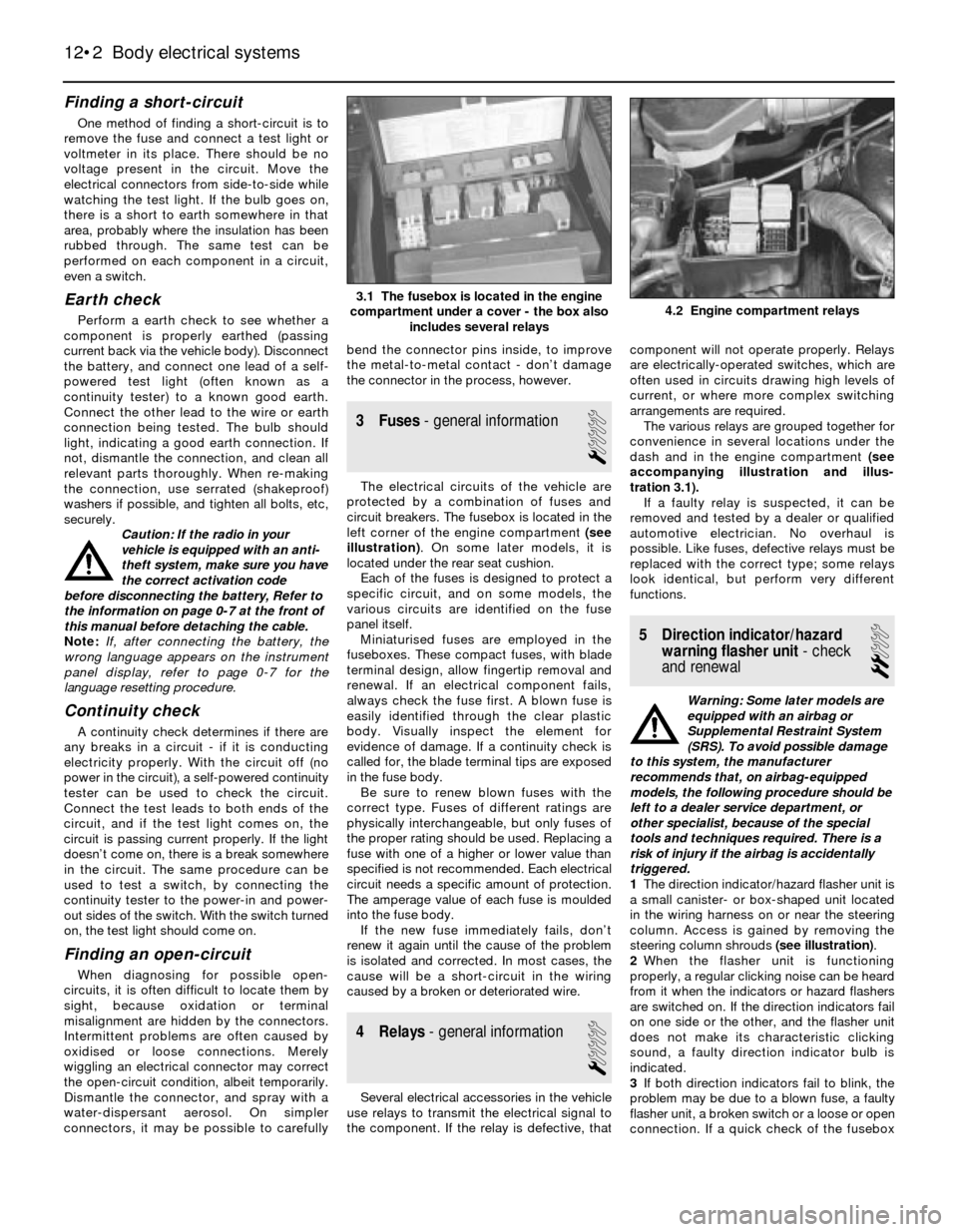
3 Fuses- general information
1
The electrical circuits of the vehicle are
protected by a combination of fuses and
circuit breakers. The fusebox is located in the
left corner of the engine compartment (see
illustration). On some later models, it is
located under the rear seat cushion.
Each of the fuses is designed to protect a
specific circuit, and on some models, the
various circuits are identified on the fuse
panel itself.
Miniaturised fuses are employed in the
fuseboxes. These compact fuses, with blade
terminal design, allow fingertip removal and
renewal. If an electrical component fails,
always check the fuse first. A blown fuse is
easily identified through the clear plastic
body. Visually inspect the element for
evidence of damage. If a continuity check is
called for, the blade terminal tips are exposed
in the fuse body.
Be sure to renew blown fuses with the
correct type. Fuses of different ratings are
physically interchangeable, but only fuses of
the proper rating should be used. Replacing a
fuse with one of a higher or lower value than
specified is not recommended. Each electrical
circuit needs a specific amount of protection.
The amperage value of each fuse is moulded
into the fuse body.
If the new fuse immediately fails, don’t
renew it again until the cause of the problem
is isolated and corrected. In most cases, the
cause will be a short-circuit in the wiring
caused by a broken or deteriorated wire.
4 Relays- general information
1
Several electrical accessories in the vehicle
use relays to transmit the electrical signal to
the component. If the relay is defective, thatcomponent will not operate properly. Relays
are electrically-operated switches, which are
often used in circuits drawing high levels of
current, or where more complex switching
arrangements are required.
The various relays are grouped together for
convenience in several locations under the
dash and in the engine compartment (see
accompanying illustration and illus-
tration 3.1).
If a faulty relay is suspected, it can be
removed and tested by a dealer or qualified
automotive electrician. No overhaul is
possible. Like fuses, defective relays must be
replaced with the correct type; some relays
look identical, but perform very different
functions.
5 Direction indicator/hazard
warning flasher unit- check
and renewal
2
Warning: Some later models are
equipped with an airbag or
Supplemental Restraint System
(SRS). To avoid possible damage
to this system, the manufacturer
recommends that, on airbag-equipped
models, the following procedure should be
left to a dealer service department, or
other specialist, because of the special
tools and techniques required. There is a
risk of injury if the airbag is accidentally
triggered.
1The direction indicator/hazard flasher unit is
a small canister- or box-shaped unit located
in the wiring harness on or near the steering
column. Access is gained by removing the
steering column shrouds (see illustration).
2When the flasher unit is functioning
properly, a regular clicking noise can be heard
from it when the indicators or hazard flashers
are switched on. If the direction indicators fail
on one side or the other, and the flasher unit
does not make its characteristic clicking
sound, a faulty direction indicator bulb is
indicated.
3If both direction indicators fail to blink, the
problem may be due to a blown fuse, a faulty
flasher unit, a broken switch or a loose or open
connection. If a quick check of the fusebox
12•2 Body electrical systems
4.2 Engine compartment relays3.1 The fusebox is located in the engine
compartment under a cover - the box also
includes several relays
Page 173 of 228
SI board is a self-contained computer which
includes a chip and batteries.
The rechargeable SI board nickel cadmium
(nicad) batteries maintain power to the
computer memory in the event of a power
drop (such as during starting) or complete
power loss (such as a dead or disconnected
battery) (see illustration). This assures power
so the computer can continue to keep track of
mileage and turn the lights on at the proper
interval.
The batteries have a life of approximately
six years, at which time they must be replaced
with new ones. Also, since they are recharged
by the engine charging system, they can run
down prematurely if power is cut off for some
reason (such as a blown fuse, a fault in the
wiring, or extended storage of the vehicle).
Excessive heat or cold can also shorten
battery life, with heat the greatest enemy.
Extreme heat can cause the batteries to
actually split open, allowing acid to drip into
the instrument cluster.
Several instruments controlled by the SI
board can be affected by low or discharged
batteries. Symptoms of low or dead SI board
batteries can include inconsistent tachometer
and temperature gauge readings, background
radio noise, and the inability to turn the
service lights off with the special tool.
Although only complete SI boards are
available from the manufacturer, batteries are
available separately from aftermarket sources.
While it is possible for the home mechanic to
renew the batteries, they are soldered to the
board, so unless you are skilled at this and
have the proper tools, this job should be left
to an experienced electronics technician.
Considerable savings can be realised by
removing the instrument cluster (see
Section 10) and taking it to an electronics
specialist.
Caution: the instrument cluster
and components are very
susceptible to damage from
static electricity. Make sure you
are earthed and have discharged any
static electricity (by touching an object
such as a metal water pipe) before
touching the cluster components.12 Headlights- bulb renewal
1
Caution: If the radio in your
vehicle is equipped with an anti-
theft system, make sure you have
the correct activation code
before disconnecting the battery, Refer to
the information on page 0-7 at the front of
this manual before detaching the cable.
Note: If, after connecting the battery, the
wrong language appears on the instrument
panel display, refer to page 0-7 for the
language resetting procedure.
1Disconnect the battery negative cable.
Sealed-beam type
2Remove the grille (see Chapter 11).
3Remove the headlight retainer screws,
taking care not to disturb the adjustment
screws.
4Remove the retainer and pull the headlight
out enough to allow the connector to be
unplugged.
5Remove the headlight.
6To refit the headlight, plug the connector in,
place the headlight in position, and refit the
retainer and screws. Tighten the screws
securely.7Refit the grille. Connect the battery negative
cable.
Halogen bulb type
Warning: Halogen gas-filled bulbs
are under pressure, and may
shatter if the surface is scratched
or the bulb is dropped. Wear eye
protection, and handle the bulbs carefully,
grasping only the base whenever possible.
Do not touch the surface of the bulb with
your fingers, because the oil from your
skin could cause it to overheat and fail
prematurely.
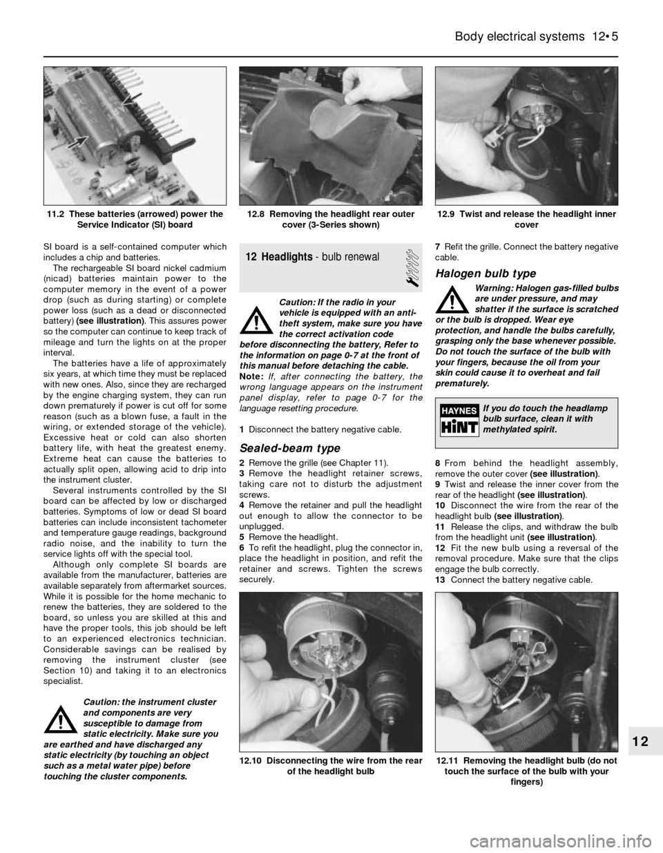
8From behind the headlight assembly,
remove the outer cover (see illustration).
9Twist and release the inner cover from the
rear of the headlight (see illustration).
10Disconnect the wire from the rear of the
headlight bulb (see illustration).
11Release the clips, and withdraw the bulb
from the headlight unit (see illustration).
12Fit the new bulb using a reversal of the
removal procedure. Make sure that the clips
engage the bulb correctly.
13Connect the battery negative cable.
Body electrical systems 12•5
12.9 Twist and release the headlight inner
cover12.8 Removing the headlight rear outer
cover (3-Series shown)11.2 These batteries (arrowed) power the
Service Indicator (SI) board
12.11 Removing the headlight bulb (do not
touch the surface of the bulb with your
fingers)12.10 Disconnecting the wire from the rear
of the headlight bulb
12
If you do touch the headlamp
bulb surface, clean it with
methylated spirit.