washer BMW 3 SERIES 1990 E30 Workshop Manual
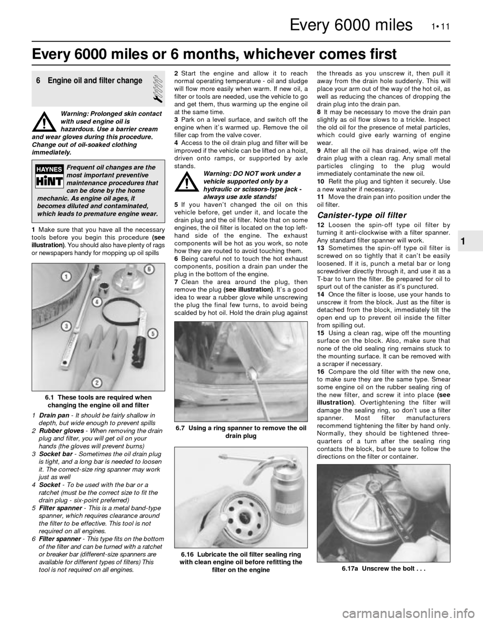
[x] Cancel search | Manufacturer: BMW, Model Year: 1990, Model line: 3 SERIES, Model: BMW 3 SERIES 1990 E30Pages: 228, PDF Size: 7.04 MB
Page 14 of 228
Maintenance schedule
The following maintenance intervals are based on the assumption
that the vehicle owner will be doing the maintenance or service work,
as opposed to having a dealer service department do the work.
Although the time/mileage intervals are loosely based on factory rec-
ommendations, most have been shortened to ensure, for example, that
such items as lubricants and fluids are checked/changed at intervals
that promote maximum engine/driveline service life. Also, subject to
the preference of the individual owner interested in keeping his or her
vehicle in peak condition at all times, and with the vehicle’s ultimate
resale in mind, many of the maintenance procedures may be
performed more often than recommended in the following schedule.
We encourage such owner initiative.
When the vehicle is new, it should be serviced initially by a factory-
authorised dealer service department, to protect the factory warranty.
In many cases, the initial maintenance check is done at no cost to the
owner (check with your dealer service department for more
information).
1•4Maintenance and servicing
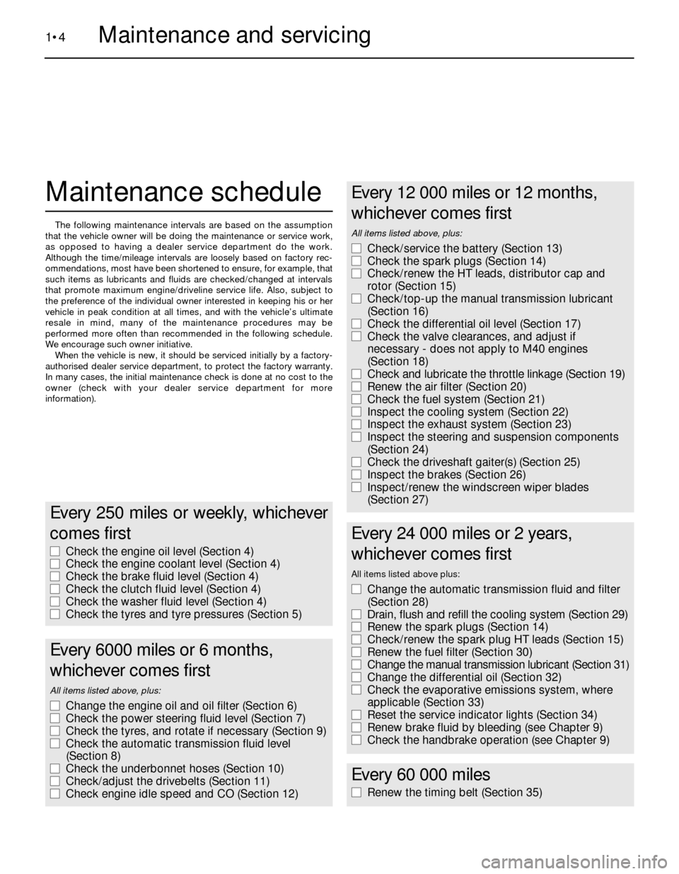
Every 250 miles or weekly, whichever
comes first
m mCheck the engine oil level (Section 4)
m mCheck the engine coolant level (Section 4)
m mCheck the brake fluid level (Section 4)
m mCheck the clutch fluid level (Section 4)
m mCheck the washer fluid level (Section 4)
m mCheck the tyres and tyre pressures (Section 5)
Every 6000 miles or 6 months,
whichever comes first
All items listed above, plus:
m mChange the engine oil and oil filter (Section 6)
m mCheck the power steering fluid level (Section 7)
m mCheck the tyres, and rotate if necessary (Section 9)
m mCheck the automatic transmission fluid level
(Section 8)
m mCheck the underbonnet hoses (Section 10)
m mCheck/adjust the drivebelts (Section 11)
m mCheck engine idle speed and CO (Section 12)
Every 12 000 miles or 12 months,
whichever comes first
All items listed above, plus:
m mCheck/service the battery (Section 13)
m mCheck the spark plugs (Section 14)
m mCheck/renew the HT leads, distributor cap and
rotor (Section 15)
m mCheck/top-up the manual transmission lubricant
(Section 16)
m mCheck the differential oil level (Section 17)
m mCheck the valve clearances, and adjust if
necessary - does not apply to M40 engines
(Section 18)
m mCheck and lubricate the throttle linkage (Section 19)
m mRenew the air filter (Section 20)
m mCheck the fuel system (Section 21)
m mInspect the cooling system (Section 22)
m mInspect the exhaust system (Section 23)
m mInspect the steering and suspension components
(Section 24)
m mCheck the driveshaft gaiter(s) (Section 25)
m mInspect the brakes (Section 26)
m mInspect/renew the windscreen wiper blades
(Section 27)
Every 24 000 miles or 2 years,
whichever comes first
All items listed above plus:
m mChange the automatic transmission fluid and filter
(Section 28)
m mDrain, flush and refill the cooling system (Section 29)
m mRenew the spark plugs (Section 14)
m mCheck/renew the spark plug HT leads (Section 15)
m mRenew the fuel filter (Section 30)
m mChange the manual transmission lubricant (Section 31)
m mChange the differential oil (Section 32)
m mCheck the evaporative emissions system, where
applicable (Section 33)
m mReset the service indicator lights (Section 34)
m mRenew brake fluid by bleeding (see Chapter 9)
m mCheck the handbrake operation (see Chapter 9)
Every 60 000 miles
m
mRenew the timing belt (Section 35)
Page 15 of 228
1•5
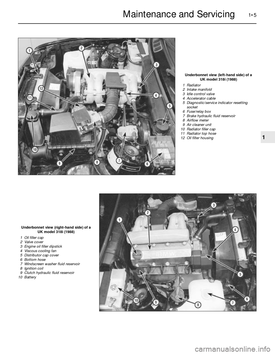
Underbonnet view (left-hand side) of a
UK model 318i (1988)
1 Radiator
2 Intake manifold
3 Idle control valve
4 Accelerator cable
5 Diagnostic/service indicator resetting
socket
6 Fuse/relay box
7 Brake hydraulic fluid reservoir
8 Airflow meter
9 Air cleaner unit
10 Radiator filler cap
11 Radiator top hose
12 Oil filter housing
Underbonnet view (right-hand side) of a
UK model 318i (1988)
1 Oil filler cap
2 Valve cover
3 Engine oil filler dipstick
4 Viscous cooling fan
5 Distributor cap cover
6 Bottom hose
7 Windscreen washer fluid reservoir
8 Ignition coil
9 Clutch hydraulic fluid reservoir
10 Battery
1
Maintenance and Servicing
Page 17 of 228
1 Introduction
This Chapter is designed to help the home
mechanic maintain his or her vehicle with the
goals of maximum performance, economy,
safety and reliability in mind. Included is a
master maintenance schedule, followed by
procedures dealing specifically with each item
on the schedule. Visual checks, adjustments,
component renewal and other helpful items
are included. Refer to the accompanying
illustrations of the engine compartment and
the underside of the vehicle for the locations
of various components. Servicing the vehicle,
in accordance with the mileage/time
maintenance schedule and the step-by-step
procedures, will result in a planned
maintenance programme that should produce
a long and reliable service life. Keep in mind
that it is a comprehensive plan, so maintaining
some items but not others at specified
intervals, will not produce the same results.
2 Routine maintenance
As you service the vehicle, you will discover
that many of the procedures can - and should
- be grouped together, because of the nature
of the particular procedure you’re performing,
or because of the close proximity of two
otherwise-unrelated components to one
another. For example, if the vehicle is raised
for chassis lubrication, you should inspect the
exhaust, suspension, steering and fuelsystems while you’re under the vehicle. When
the wheels are removed for other work, it
makes good sense to check the brakes, since
the wheels are already removed. Finally, let’s
suppose you have to borrow a torque wrench.
Even if you only need it to tighten the spark
plugs, you might as well check the torque of
as many critical nuts and bolts as time allows.
The first step in this maintenance
programme is to prepare yourself before the
actual work begins. Read through all the
procedures you’re planning to do, then gather
up all the parts and tools needed. If it looks
like you might run into problems during a
particular job, seek advice from a mechanic or
an experienced do-it-yourselfer.
3 Engine “tune-up”-
general information
The term “tune-up” is used in this manual to
represent a combination of individual
operations rather than one specific procedure.
If, from the time the vehicle is new, the
routine maintenance schedule is followed
closely, and frequent checks are made of fluid
levels and high-wear items, as suggested
throughout this manual, the engine will be
kept in relatively good running condition, and
the need for additional work will be minimised.
More likely than not, however, there will be
times when the engine is running poorly due
to a lack of regular maintenance. This is even
more likely if a used vehicle, which has not
received regular and frequent maintenance
checks, is purchased. In such cases, an
engine tune-up will be needed outside of the
regular maintenance intervals. The first step in any tune-up or diagnostic
procedure to help correct a poor-running
engine is a cylinder compression check. A
compression check (see Chapter 2B) will help
determine the condition of internal engine
components, and should be used as a guide
for tune-up and repair procedures. If, for
instance, a compression check indicates
serious internal engine wear, a conventional
tune-up will not improve the performance of
the engine, and would be a waste of time and
money. Because of its importance, the
compression check should be done by
someone with the right equipment, and the
knowledge to use it properly.
The following procedures are those most
often needed to bring a generally poor-
running engine back into a proper state of
tune.
Minor tune-up
Check all engine-related fluids (Section 4)
Check all underbonnet hoses (Section 10)
Check and adjust the drivebelts (Sec-
tion 11)
Clean, inspect and test the battery (Sec-
tion 13)
Renew the spark plugs (Section 14)
Inspect the spark plug HT leads, distributor
cap and rotor (Section 15)
Check the air filter (Section 20)
Check the cooling system (Section 22)
Major tune-up
All items listed under minor tune-up, plus . . .
Check the ignition system (see Chapter 5)
Check the charging system (see Chapter 5)
Check the fuel system (see Chapter 4)
Renew the spark plug HT leads, distributor
cap and rotor (Section 15)
1•7
1
Routine Maintenance
Weekly checks
4 Fluid level checks
1
Note:The following are fluid level checks to
be done on a 250-mile or weekly basis.
Additional fluid level checks can be found in
specific maintenance procedures which
follow. Regardless of intervals, be alert to fluid
leaks under the vehicle, which would indicate
a fault to be corrected immediately.
1Fluids are an essential part of the
lubrication, cooling, brake and windscreen
washer systems. Because the fluids gradually
become depleted and/or contaminated during
normal operation of the vehicle, they must be
periodically replenished. See “Lubricants and
fluids”at the beginning of this Chapter before
adding fluid to any of the following
components. Note:The vehicle must be on
level ground when any fluid levels are
checked.
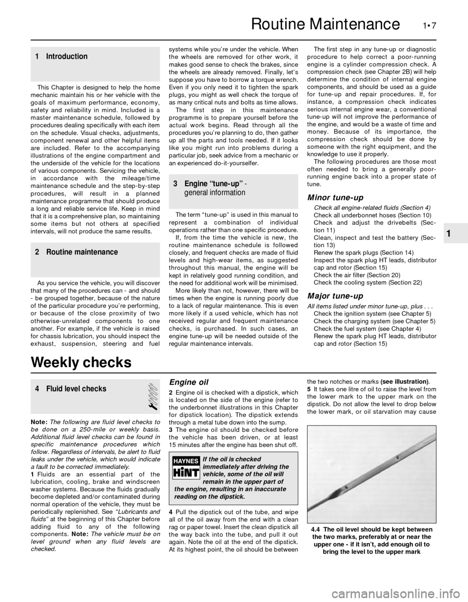
Engine oil
2Engine oil is checked with a dipstick, which
is located on the side of the engine (refer to
the underbonnet illustrations in this Chapter
for dipstick location). The dipstick extends
through a metal tube down into the sump.
3The engine oil should be checked before
the vehicle has been driven, or at least
15 minutes after the engine has been shut off.
4Pull the dipstick out of the tube, and wipe
all of the oil away from the end with a clean
rag or paper towel. Insert the clean dipstick all
the way back into the tube, and pull it out
again. Note the oil at the end of the dipstick.
At its highest point, the oil should be betweenthe two notches or marks (see illustration).
5It takes one litre of oil to raise the level from
the lower mark to the upper mark on the
dipstick. Do not allow the level to drop below
the lower mark, or oil starvation may cause
4.4 The oil level should be kept between
the two marks, preferably at or near the
upper one - if it isn’t, add enough oil to
bring the level to the upper mark
If the oil is checked
immediately after driving the
vehicle, some of the oil will
remain in the upper part of
the engine, resulting in an inaccurate
reading on the dipstick.
Page 19 of 228
inhibitors wear out, so it must be renewed at
the specified intervals.
Brake and clutch fluid
Warning: Brake fluid can harm
your eyes and damage painted
surfaces, so use extreme caution
when handling or pouring it. Do
not use brake fluid that has been standing
open or is more than one year old. Brake
fluid absorbs moisture from the air, which
can cause a dangerous loss of brake
effectiveness. Use only the specified type
of brake fluid. Mixing different types (such
as DOT 3 or 4 and DOT 5) can cause brake
failure.
14The brake master cylinder is mounted at
the left rear corner of the engine
compartment. The clutch fluid reservoir
(manual transmission models) is mounted on
the right-hand side.
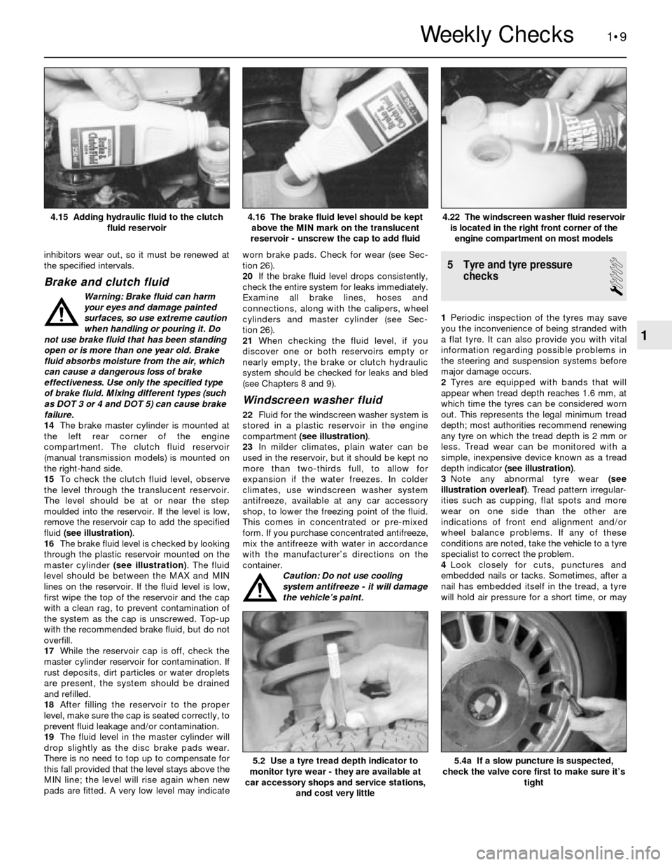
15To check the clutch fluid level, observe
the level through the translucent reservoir.
The level should be at or near the step
moulded into the reservoir. If the level is low,
remove the reservoir cap to add the specified
fluid (see illustration).
16The brake fluid level is checked by looking
through the plastic reservoir mounted on the
master cylinder (see illustration). The fluid
level should be between the MAX and MIN
lines on the reservoir. If the fluid level is low,
first wipe the top of the reservoir and the cap
with a clean rag, to prevent contamination of
the system as the cap is unscrewed. Top-up
with the recommended brake fluid, but do not
overfill.
17While the reservoir cap is off, check the
master cylinder reservoir for contamination. If
rust deposits, dirt particles or water droplets
are present, the system should be drained
and refilled.
18After filling the reservoir to the proper
level, make sure the cap is seated correctly, to
prevent fluid leakage and/or contamination.
19The fluid level in the master cylinder will
drop slightly as the disc brake pads wear.
There is no need to top up to compensate for
this fall provided that the level stays above the
MIN line; the level will rise again when new
pads are fitted. A very low level may indicateworn brake pads. Check for wear (see Sec-
tion 26).
20If the brake fluid level drops consistently,
check the entire system for leaks immediately.
Examine all brake lines, hoses and
connections, along with the calipers, wheel
cylinders and master cylinder (see Sec-
tion 26).
21When checking the fluid level, if you
discover one or both reservoirs empty or
nearly empty, the brake or clutch hydraulic
system should be checked for leaks and bled
(see Chapters 8 and 9).
Windscreen washer fluid
22Fluid for the windscreen washer system is
stored in a plastic reservoir in the engine
compartment (see illustration).
23In milder climates, plain water can be
used in the reservoir, but it should be kept no
more than two-thirds full, to allow for
expansion if the water freezes. In colder
climates, use windscreen washer system
antifreeze, available at any car accessory
shop, to lower the freezing point of the fluid.
This comes in concentrated or pre-mixed
form. If you purchase concentrated antifreeze,
mix the antifreeze with water in accordance
with the manufacturer’s directions on the
container.
Caution: Do not use cooling
system antifreeze - it will damage
the vehicle’s paint.
5 Tyre and tyre pressure
checks
1
1Periodic inspection of the tyres may save
you the inconvenience of being stranded with
a flat tyre. It can also provide you with vital
information regarding possible problems in
the steering and suspension systems before
major damage occurs.
2Tyres are equipped with bands that will
appear when tread depth reaches 1.6 mm, at
which time the tyres can be considered worn
out. This represents the legal minimum tread
depth; most authorities recommend renewing
any tyre on which the tread depth is 2 mm or
less. Tread wear can be monitored with a
simple, inexpensive device known as a tread
depth indicator (see illustration).
3Note any abnormal tyre wear (see
illustration overleaf). Tread pattern irregular-
ities such as cupping, flat spots and more
wear on one side than the other are
indications of front end alignment and/or
wheel balance problems. If any of these
conditions are noted, take the vehicle to a tyre
specialist to correct the problem.
4Look closely for cuts, punctures and
embedded nails or tacks. Sometimes, after a
nail has embedded itself in the tread, a tyre
will hold air pressure for a short time, or may
1•9
4.22 The windscreen washer fluid reservoir
is located in the right front corner of the
engine compartment on most models4.16 The brake fluid level should be kept
above the MIN mark on the translucent
reservoir - unscrew the cap to add fluid4.15 Adding hydraulic fluid to the clutch
fluid reservoir
5.4a If a slow puncture is suspected,
check the valve core first to make sure it’s
tight5.2 Use a tyre tread depth indicator to
monitor tyre wear - they are available at
car accessory shops and service stations,
and cost very little
1
Weekly Checks
Page 21 of 228
Every 6000 miles or 6 months, whichever comes first
1•11
6.17a Unscrew the bolt . . .
1
Every 6000 miles
6 Engine oil and filter change
1
Warning: Prolonged skin contact
with used engine oil is
hazardous. Use a barrier cream
and wear gloves during this procedure.
Change out of oil-soaked clothing
immediately.
1Make sure that you have all the necessary
tools before you begin this procedure (see
illustration). You should also have plenty of rags
or newspapers handy for mopping up oil spills2Start the engine and allow it to reach
normal operating temperature - oil and sludge
will flow more easily when warm. If new oil, a
filter or tools are needed, use the vehicle to go
and get them, thus warming up the engine oil
at the same time.
3Park on a level surface, and switch off the
engine when it’s warmed up. Remove the oil
filler cap from the valve cover.
4Access to the oil drain plug and filter will be
improved if the vehicle can be lifted on a hoist,
driven onto ramps, or supported by axle
stands.
Warning: DO NOT work under a
vehicle supported only by a
hydraulic or scissors-type jack -
always use axle stands!
5If you haven’t changed the oil on this
vehicle before, get under it, and locate the
drain plug and the oil filter. Note that on some
engines, the oil filter is located on the top left-
hand side of the engine. The exhaust
components will be hot as you work, so note
how they are routed to avoid touching them.
6Being careful not to touch the hot exhaust
components, position a drain pan under the
plug in the bottom of the engine.
7Clean the area around the plug, then
remove the plug (see illustration). It’s a good
idea to wear a rubber glove while unscrewing
the plug the final few turns, to avoid being
scalded by hot oil. Hold the drain plug againstthe threads as you unscrew it, then pull it
away from the drain hole suddenly. This will
place your arm out of the way of the hot oil, as
well as reducing the chances of dropping the
drain plug into the drain pan.
8It may be necessary to move the drain pan
slightly as oil flow slows to a trickle. Inspect
the old oil for the presence of metal particles,
which could give early warning of engine
wear.
9After all the oil has drained, wipe off the
drain plug with a clean rag. Any small metal
particles clinging to the plug would
immediately contaminate the new oil.
10Refit the plug and tighten it securely. Use
a new washer if necessary.
11Move the drain pan into position under the
oil filter.
Canister-type oil filter
12Loosen the spin-off type oil filter by
turning it anti-clockwise with a filter spanner.
Any standard filter spanner will work.
13Sometimes the spin-off type oil filter is
screwed on so tightly that it can’t be easily
loosened. If it is, punch a metal bar or long
screwdriver directly through it, and use it as a
T-bar to turn the filter. Be prepared for oil to
spurt out of the canister as it’s punctured.
14Once the filter is loose, use your hands to
unscrew it from the block. Just as the filter is
detached from the block, immediately tilt the
open end up to prevent oil inside the filter
from spilling out.
15Using a clean rag, wipe off the mounting
surface on the block. Also, make sure that
none of the old sealing ring remains stuck to
the mounting surface. It can be removed with
a scraper if necessary.
16Compare the old filter with the new one,
to make sure they are the same type. Smear
some engine oil on the rubber sealing ring of
the new filter, and screw it into place (see
illustration). Overtightening the filter will
damage the sealing ring, so don’t use a filter
spanner. Most filter manufacturers
recommend tightening the filter by hand only.
Normally, they should be tightened three-
quarters of a turn after the sealing ring
contacts the block, but be sure to follow the
directions on the filter or container.
6.1 These tools are required when
changing the engine oil and filter
1 Drain pan- It should be fairly shallow in
depth, but wide enough to prevent spills
2 Rubber gloves- When removing the drain
plug and filter, you will get oil on your
hands (the gloves will prevent burns)
3 Socket bar - Sometimes the oil drain plug
is tight, and a long bar is needed to loosen
it. The correct-size ring spanner may work
just as well
4 Socket- To be used with the bar or a
ratchet (must be the correct size to fit the
drain plug - six-point preferred)
5 Filter spanner - This is a metal band-type
spanner, which requires clearance around
the filter to be effective. This tool is not
required on all engines.
6 Filter spanner- This type fits on the bottom
of the filter and can be turned with a ratchet
or breaker bar (different-size spanners are
available for different types of filters) This
tool is not required on all engines.
6.7 Using a ring spanner to remove the oil
drain plug
6.16 Lubricate the oil filter sealing ring
with clean engine oil before refitting the
filter on the engine
Frequent oil changes are the
most important preventive
maintenance procedures that
can be done by the home
mechanic. As engine oil ages, it
becomes diluted and contaminated,
which leads to premature engine wear.
Page 26 of 228
13 Battery check, maintenance
and charging
2
Check and maintenance
Warning: Certain precautions
must be followed when checking
and servicing the battery.
Hydrogen gas, which is highly
flammable, is always present in the battery
cells, so keep lighted tobacco and all other
flames and sparks away from it. The
electrolyte inside the battery is actually
dilute sulphuric acid, which will cause
injury if splashed on your skin or in youreyes. It will also ruin clothes and painted
surfaces. When disconnecting the battery
cables, always detach the negative cable
first, and connect it last!
1Battery maintenance is an important
procedure, which will help ensure that you are
not stranded because of a dead battery.
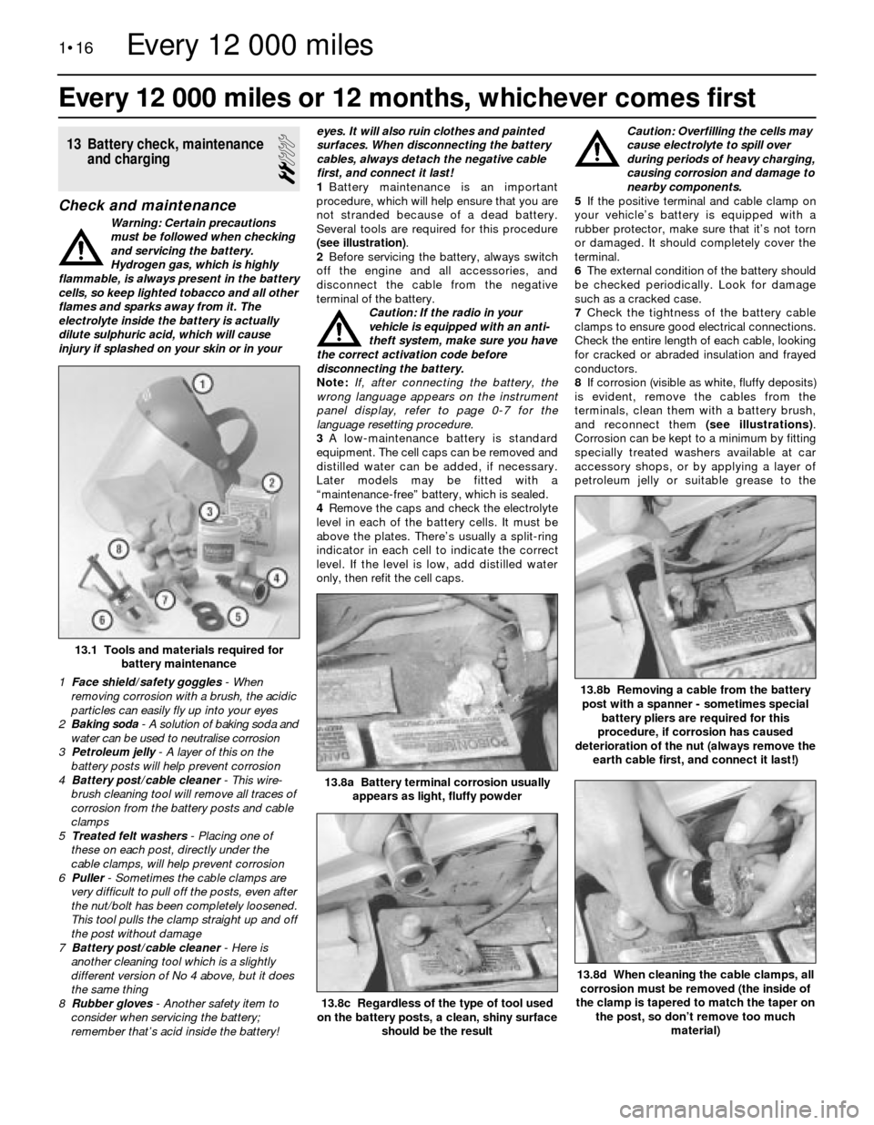
Several tools are required for this procedure
(see illustration).
2Before servicing the battery, always switch
off the engine and all accessories, and
disconnect the cable from the negative
terminal of the battery.
Caution: If the radio in your
vehicle is equipped with an anti-
theft system, make sure you have
the correct activation code before
disconnecting the battery.
Note: If, after connecting the battery, the
wrong language appears on the instrument
panel display, refer to page 0-7 for the
language resetting procedure.
3A low-maintenance battery is standard
equipment. The cell caps can be removed and
distilled water can be added, if necessary.
Later models may be fitted with a
“maintenance-free” battery, which is sealed.
4Remove the caps and check the electrolyte
level in each of the battery cells. It must be
above the plates. There’s usually a split-ring
indicator in each cell to indicate the correct
level. If the level is low, add distilled water
only, then refit the cell caps.Caution: Overfilling the cells may
cause electrolyte to spill over
during periods of heavy charging,
causing corrosion and damage to
nearby components.
5If the positive terminal and cable clamp on
your vehicle’s battery is equipped with a
rubber protector, make sure that it’s not torn
or damaged. It should completely cover the
terminal.
6The external condition of the battery should
be checked periodically. Look for damage
such as a cracked case.
7Check the tightness of the battery cable
clamps to ensure good electrical connections.
Check the entire length of each cable, looking
for cracked or abraded insulation and frayed
conductors.
8If corrosion (visible as white, fluffy deposits)
is evident, remove the cables from the
terminals, clean them with a battery brush,
and reconnect them (see illustrations).
Corrosion can be kept to a minimum by fitting
specially treated washers available at car
accessory shops, or by applying a layer of
petroleum jelly or suitable grease to the
Every 12 000 miles or 12 months, whichever comes first
1•16
13.8d When cleaning the cable clamps, all
corrosion must be removed (the inside of
the clamp is tapered to match the taper on
the post, so don’t remove too much
material)
13.8c Regardless of the type of tool used
on the battery posts, a clean, shiny surface
should be the result
13.1 Tools and materials required for
battery maintenance
1 Face shield/safety goggles- When
removing corrosion with a brush, the acidic
particles can easily fly up into your eyes
2 Baking soda - A solution of baking soda and
water can be used to neutralise corrosion
3 Petroleum jelly- A layer of this on the
battery posts will help prevent corrosion
4 Battery post/cable cleaner- This wire-
brush cleaning tool will remove all traces of
corrosion from the battery posts and cable
clamps
5 Treated felt washers- Placing one of
these on each post, directly under the
cable clamps, will help prevent corrosion
6 Puller- Sometimes the cable clamps are
very difficult to pull off the posts, even after
the nut/bolt has been completely loosened.
This tool pulls the clamp straight up and off
the post without damage
7 Battery post/cable cleaner - Here is
another cleaning tool which is a slightly
different version of No 4 above, but it does
the same thing
8 Rubber gloves- Another safety item to
consider when servicing the battery;
remember that’s acid inside the battery!
13.8b Removing a cable from the battery
post with a spanner - sometimes special
battery pliers are required for this
procedure, if corrosion has caused
deterioration of the nut (always remove the
earth cable first, and connect it last!)
13.8a Battery terminal corrosion usually
appears as light, fluffy powder
Every 12 000 miles
Page 40 of 228
12After the No 1 piston has been positioned
at TDC on the compression stroke, TDC for
any of the remaining pistons can be located
by turning the crankshaft and following the
firing order. Mark the remaining spark plug
lead terminal locations just like you did for the
No 1 terminal, then number the marks to
correspond with the cylinder numbers. As you
turn the crankshaft, the rotor will also turn.
When it’s pointing directly at one of the marks
on the distributor, the piston for that particular
cylinder is at TDC on the compression stroke.
4 Valve cover-
removal and refitting
1
Caution: If the radio in your
vehicle is equipped with an anti-
theft system, make sure you
have the correct activation code
before disconnecting the battery.
Note: If, after connecting the battery, the
wrong language appears on the instrument
panel display, refer to page 0-7 for the
language resetting procedure.
Removal
1Disconnect the battery negative cable.
2Detach the breather hose from the valve
cover.
3On M20 engines, unbolt and remove the
intake manifold support bracket and, if
applicable, the bracket for the engine sensors
or idle air stabiliser (it will probably be
necessary to disconnect the electrical
connectors from the sensors and stabiliser).
4On M30 engines, disconnect the electrical
connector for the airflow sensor. Unclip the
electrical harness, moving it out of the way.
5Where necessary on M30 engines, remove
the hoses and fittings from the intake air hose,
then loosen the clamp and separate the hose
from the throttle body. Unscrew the mounting
nuts for the air cleaner housing, and remove
the housing together with the air hose and
airflow sensor.
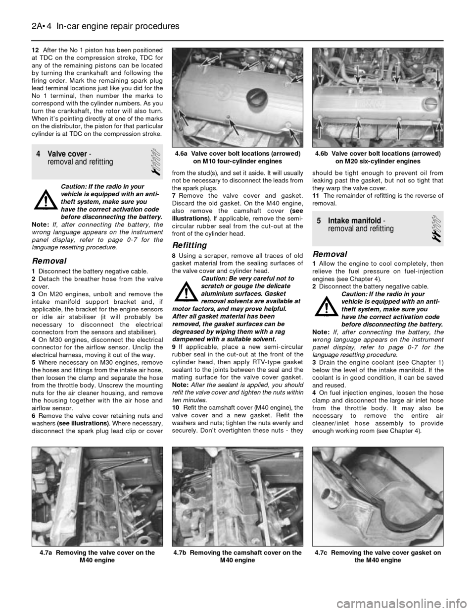
6Remove the valve cover retaining nuts and
washers (see illustrations). Where necessary,
disconnect the spark plug lead clip or coverfrom the stud(s), and set it aside. It will usually
not be necessary to disconnect the leads from
the spark plugs.
7Remove the valve cover and gasket.
Discard the old gasket. On the M40 engine,
also remove the camshaft cover (see
illustrations). If applicable, remove the semi-
circular rubber seal from the cut-out at the
front of the cylinder head.
Refitting
8Using a scraper, remove all traces of old
gasket material from the sealing surfaces of
the valve cover and cylinder head.
Caution: Be very careful not to
scratch or gouge the delicate
aluminium surfaces. Gasket
removal solvents are available at
motor factors, and may prove helpful.
After all gasket material has been
removed, the gasket surfaces can be
degreased by wiping them with a rag
dampened with a suitable solvent.
9If applicable, place a new semi-circular
rubber seal in the cut-out at the front of the
cylinder head, then apply RTV-type gasket
sealant to the joints between the seal and the
mating surface for the valve cover gasket.
Note:After the sealant is applied, you should
refit the valve cover and tighten the nuts within
ten minutes.
10Refit the camshaft cover (M40 engine), the
valve cover and a new gasket. Refit the
washers and nuts; tighten the nuts evenly and
securely. Don’t overtighten these nuts - theyshould be tight enough to prevent oil from
leaking past the gasket, but not so tight that
they warp the valve cover.
11The remainder of refitting is the reverse of
removal.
5 Intake manifold-
removal and refitting
2
Removal
1Allow the engine to cool completely, then
relieve the fuel pressure on fuel-injection
engines (see Chapter 4).
2Disconnect the battery negative cable.
Caution: If the radio in your
vehicle is equipped with an anti-
theft system, make sure you
have the correct activation code
before disconnecting the battery.
Note: If, after connecting the battery, the
wrong language appears on the instrument
panel display, refer to page 0-7 for the
language resetting procedure.
3Drain the engine coolant (see Chapter 1)
below the level of the intake manifold. If the
coolant is in good condition, it can be saved
and reused.
4On fuel injection engines, loosen the hose
clamp and disconnect the large air inlet hose
from the throttle body. It may also be
necessary to remove the entire air
cleaner/inlet hose assembly to provide
enough working room (see Chapter 4).
2A•4 In-car engine repair procedures
4.7b Removing the camshaft cover on the
M40 engine4.7a Removing the valve cover on the
M40 engine4.7c Removing the valve cover gasket on
the M40 engine
4.6b Valve cover bolt locations (arrowed)
on M20 six-cylinder engines4.6a Valve cover bolt locations (arrowed)
on M10 four-cylinder engines
Page 42 of 228
6 Exhaust manifold-
removal and refitting
1
Warning: Make sure the engine is
completely cool before beginning
work on the exhaust system.
Caution: If the radio in your
vehicle is equipped with an anti-
theft system, make sure you
have the correct activation code
before disconnecting the battery.
Note: If, after connecting the battery, the
wrong language appears on the instrument
panel display, refer to page 0-7 for the
language resetting procedure.
1Disconnect the battery negative cable.
2On models where the air cleaner is on the
exhaust manifold side of the engine, remove
the air cleaner housing assembly and/or
airflow sensor to provide sufficient working
area (see Chapter 4, if necessary).
3Unplug the HT leads and set the spark plug
lead harness aside (see Chapter 1).
4Clearly label, then disconnect or remove, all
wires, hoses, fittings, etc. that are in the way.
Be sure to disconnect the oxygen sensor,
where fitted.
5Raise the vehicle, and support it securely
on axle stands. Working from under the
vehicle, separate the exhaust downpipe from
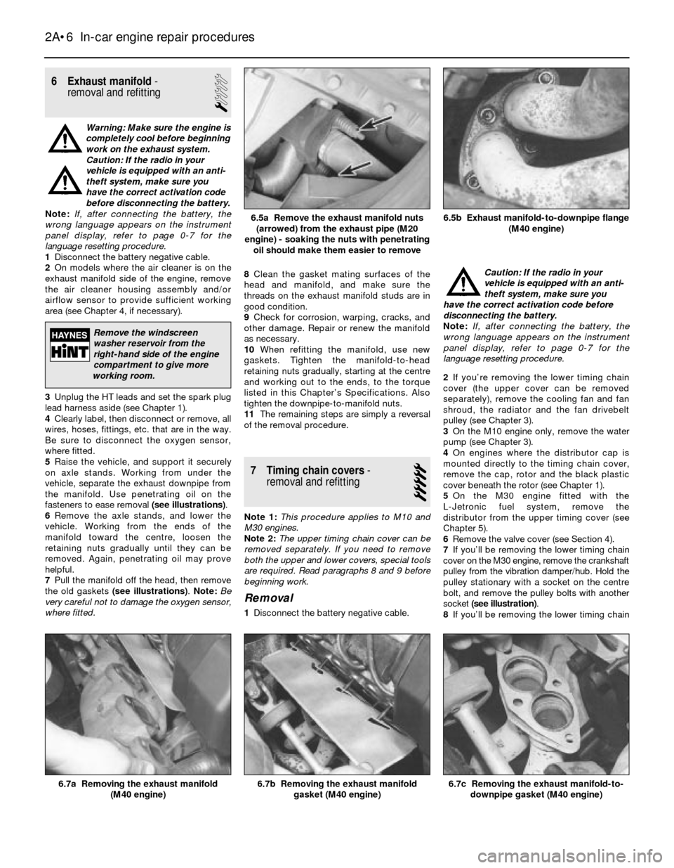
the manifold. Use penetrating oil on the
fasteners to ease removal (see illustrations).
6Remove the axle stands, and lower the
vehicle. Working from the ends of the
manifold toward the centre, loosen the
retaining nuts gradually until they can be
removed. Again, penetrating oil may prove
helpful.
7Pull the manifold off the head, then remove
the old gaskets (see illustrations). Note:Be
very careful not to damage the oxygen sensor,
where fitted.8Clean the gasket mating surfaces of the
head and manifold, and make sure the
threads on the exhaust manifold studs are in
good condition.
9Check for corrosion, warping, cracks, and
other damage. Repair or renew the manifold
as necessary.
10When refitting the manifold, use new
gaskets. Tighten the manifold-to-head
retaining nuts gradually, starting at the centre
and working out to the ends, to the torque
listed in this Chapter’s Specifications. Also
tighten the downpipe-to-manifold nuts.
11The remaining steps are simply a reversal
of the removal procedure.
7 Timing chain covers-
removal and refitting
5
Note 1:This procedure applies to M10 and
M30 engines.
Note 2:The upper timing chain cover can be
removed separately. If you need to remove
both the upper and lower covers, special tools
are required. Read paragraphs 8 and 9 before
beginning work.
Removal
1Disconnect the battery negative cable.Caution: If the radio in your
vehicle is equipped with an anti-
theft system, make sure you
have the correct activation code before
disconnecting the battery.
Note: If, after connecting the battery, the
wrong language appears on the instrument
panel display, refer to page 0-7 for the
language resetting procedure.
2If you’re removing the lower timing chain
cover (the upper cover can be removed
separately), remove the cooling fan and fan
shroud, the radiator and the fan drivebelt
pulley (see Chapter 3).
3On the M10 engine only, remove the water
pump (see Chapter 3).
4On engines where the distributor cap is
mounted directly to the timing chain cover,
remove the cap, rotor and the black plastic
cover beneath the rotor (see Chapter 1).
5On the M30 engine fitted with the
L-Jetronic fuel system, remove the
distributor from the upper timing cover (see
Chapter 5).
6Remove the valve cover (see Section 4).
7If you’ll be removing the lower timing chain
cover on the M30 engine, remove the crankshaft
pulley from the vibration damper/hub. Hold the
pulley stationary with a socket on the centre
bolt, and remove the pulley bolts with another
socket (see illustration).
8If you’ll be removing the lower timing chain
2A•6 In-car engine repair procedures
6.7c Removing the exhaust manifold-to-
downpipe gasket (M40 engine)6.7b Removing the exhaust manifold
gasket (M40 engine)6.7a Removing the exhaust manifold
(M40 engine)
6.5b Exhaust manifold-to-downpipe flange
(M40 engine)6.5a Remove the exhaust manifold nuts
(arrowed) from the exhaust pipe (M20
engine) - soaking the nuts with penetrating
oil should make them easier to remove
Remove the windscreen
washer reservoir from the
right-hand side of the engine
compartment to give more
working room.
Page 62 of 228
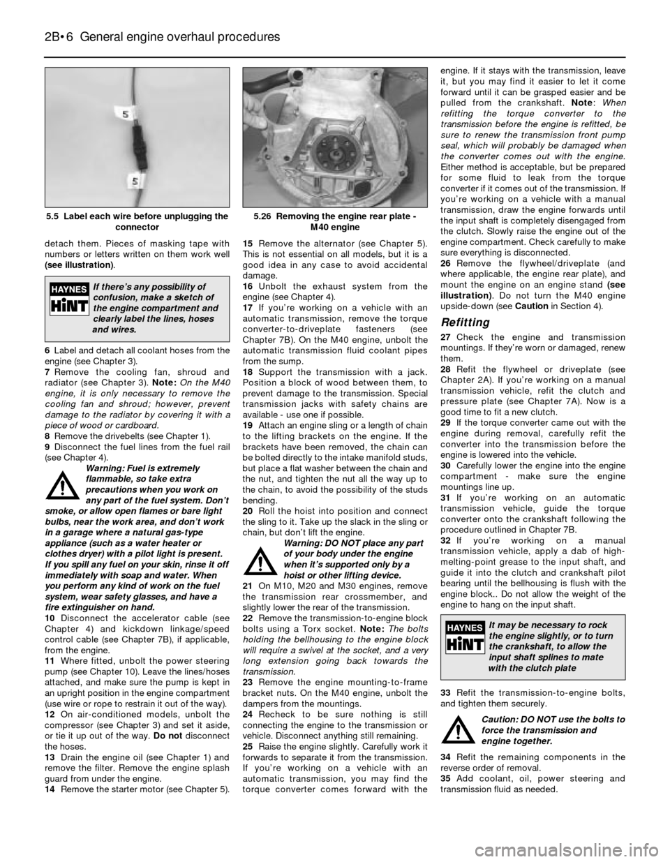
detach them. Pieces of masking tape with
numbers or letters written on them work well
(see illustration).
6Label and detach all coolant hoses from the
engine (see Chapter 3).
7Remove the cooling fan, shroud and
radiator (see Chapter 3). Note:On the M40
engine, it is only necessary to remove the
cooling fan and shroud; however, prevent
damage to the radiator by covering it with a
piece of wood or cardboard.
8Remove the drivebelts (see Chapter 1).
9Disconnect the fuel lines from the fuel rail
(see Chapter 4).
Warning: Fuel is extremely
flammable, so take extra
precautions when you work on
any part of the fuel system. Don’t
smoke, or allow open flames or bare light
bulbs, near the work area, and don’t work
in a garage where a natural gas-type
appliance (such as a water heater or
clothes dryer) with a pilot light is present.
If you spill any fuel on your skin, rinse it off
immediately with soap and water. When
you perform any kind of work on the fuel
system, wear safety glasses, and have a
fire extinguisher on hand.
10Disconnect the accelerator cable (see
Chapter 4) and kickdown linkage/speed
control cable (see Chapter 7B), if applicable,
from the engine.
11Where fitted, unbolt the power steering
pump (see Chapter 10). Leave the lines/hoses
attached, and make sure the pump is kept in
an upright position in the engine compartment
(use wire or rope to restrain it out of the way).
12On air-conditioned models, unbolt the
compressor (see Chapter 3) and set it aside,
or tie it up out of the way. Do not disconnect
the hoses.
13Drain the engine oil (see Chapter 1) and
remove the filter. Remove the engine splash
guard from under the engine.
14Remove the starter motor (see Chapter 5).15Remove the alternator (see Chapter 5).
This is not essential on all models, but it is a
good idea in any case to avoid accidental
damage.
16Unbolt the exhaust system from the
engine (see Chapter 4).
17If you’re working on a vehicle with an
automatic transmission, remove the torque
converter-to-driveplate fasteners (see
Chapter 7B). On the M40 engine, unbolt the
automatic transmission fluid coolant pipes
from the sump.
18Support the transmission with a jack.
Position a block of wood between them, to
prevent damage to the transmission. Special
transmission jacks with safety chains are
available - use one if possible.
19Attach an engine sling or a length of chain
to the lifting brackets on the engine. If the
brackets have been removed, the chain can
be bolted directly to the intake manifold studs,
but place a flat washer between the chain and
the nut, and tighten the nut all the way up to
the chain, to avoid the possibility of the studs
bending.
20Roll the hoist into position and connect
the sling to it. Take up the slack in the sling or
chain, but don’t lift the engine.
Warning: DO NOT place any part
of your body under the engine
when it’s supported only by a
hoist or other lifting device.
21On M10, M20 and M30 engines, remove
the transmission rear crossmember, and
slightly lower the rear of the transmission.
22Remove the transmission-to-engine block
bolts using a Torx socket. Note:The bolts
holding the bellhousing to the engine block
will require a swivel at the socket, and a very
long extension going back towards the
transmission.
23Remove the engine mounting-to-frame
bracket nuts. On the M40 engine, unbolt the
dampers from the mountings.
24Recheck to be sure nothing is still
connecting the engine to the transmission or
vehicle. Disconnect anything still remaining.
25Raise the engine slightly. Carefully work it
forwards to separate it from the transmission.
If you’re working on a vehicle with an
automatic transmission, you may find the
torque converter comes forward with theengine. If it stays with the transmission, leave
it, but you may find it easier to let it come
forward until it can be grasped easier and be
pulled from the crankshaft. Note:When
refitting the torque converter to the
transmission before the engine is refitted, be
sure to renew the transmission front pump
seal, which will probably be damaged when
the converter comes out with the engine.
Either method is acceptable, but be prepared
for some fluid to leak from the torque
converter if it comes out of the transmission. If
you’re working on a vehicle with a manual
transmission, draw the engine forwards until
the input shaft is completely disengaged from
the clutch. Slowly raise the engine out of the
engine compartment. Check carefully to make
sure everything is disconnected.
26Remove the flywheel/driveplate (and
where applicable, the engine rear plate), and
mount the engine on an engine stand (see
illustration). Do not turn the M40 engine
upside-down (see Cautionin Section 4).
Refitting
27Check the engine and transmission
mountings. If they’re worn or damaged, renew
them.
28Refit the flywheel or driveplate (see
Chapter 2A). If you’re working on a manual
transmission vehicle, refit the clutch and
pressure plate (see Chapter 7A). Now is a
good time to fit a new clutch.
29If the torque converter came out with the
engine during removal, carefully refit the
converter into the transmission before the
engine is lowered into the vehicle.
30Carefully lower the engine into the engine
compartment - make sure the engine
mountings line up.
31If you’re working on an automatic
transmission vehicle, guide the torque
converter onto the crankshaft following the
procedure outlined in Chapter 7B.
32If you’re working on a manual
transmission vehicle, apply a dab of high-
melting-point grease to the input shaft, and
guide it into the clutch and crankshaft pilot
bearing until the bellhousing is flush with the
engine block.. Do not allow the weight of the
engine to hang on the input shaft.
33Refit the transmission-to-engine bolts,
and tighten them securely.
Caution: DO NOT use the bolts to
force the transmission and
engine together.
34Refit the remaining components in the
reverse order of removal.
35Add coolant, oil, power steering and
transmission fluid as needed.
2B•6 General engine overhaul procedures
5.26 Removing the engine rear plate -
M40 engine5.5 Label each wire before unplugging the
connector
If there’s any possibility of
confusion, make a sketch of
the engine compartment and
clearly label the lines, hoses
and wires.
It may be necessary to rock
the engine slightly, or to turn
the crankshaft, to allow the
input shaft splines to mate
with the clutch plate
Page 63 of 228
36Run the engine and check for leaks and
proper operation of all accessories, then refit
the bonnet and test drive the vehicle.
37Where necessary, have the air
conditioning system recharged and leak-
tested.
6 Engine overhaul- alternatives
The do-it-yourselfer is faced with a number
of options when performing an engine
overhaul. The decision to renew the engine
block, piston/connecting rod assemblies and
crankshaft depends on a number of factors,
with the number one consideration being the
condition of the block. Other considerations
are cost, access to machine shop facilities,
parts availability, time required to complete
the project, and the extent of prior mechanical
experience on the part of the do-it-yourselfer.
Some of the alternatives include:
Individual parts - If the inspection
procedures reveal that the engine block and
most engine components are in re-usable
condition, purchasing individual parts may be
the most economical alternative. The block,
crankshaft and piston/connecting rod
assemblies should all be inspected carefully.
Even if the block shows little wear, the
cylinder bores should be surface-honed.
Crankshaft kit- A crankshaft kit (where
available) consists of a reground crankshaft
with matched undersize new main and
connecting big-end bearings. Sometimes,
reconditioned connecting rods and new
pistons and rings are included with the kit
(such a kit is sometimes called an “engine
kit”). If the block is in good condition, but the
crankshaft journals are scored or worn, a
crankshaft kit and other individual parts may
be the most economical alternative.
Short block- A short block consists of an
engine block with a crankshaft and
piston/connecting rod assemblies already
fitted. New bearings are fitted, and all
clearances will be correct. The existing
camshaft, valve train components, cylinder
head and external parts can be bolted to the
short block with little or no machine shop
work necessary.
Full block - A “full” or “complete” block
consists of a short block plus an oil pump,
sump, cylinder head, valve cover, camshaft
and valve train components, timing sprockets
and chain (or belt) and timing cover. All
components are fitted with new bearings,
seals and gaskets used throughout. The
refitting of manifolds and external parts is all
that’s necessary.
Give careful thought to which alternative is
best for you, and discuss the situation with
local machine shops, parts dealers and
experienced rebuilders before ordering or
purchasing new parts.
7 Engine overhaul-
dismantling sequence
1It’s much easier to dismantle and work on
the engine if it’s mounted on a portable
engine stand. A stand can often be hired quite
cheaply from a tool hire shop. Before the
engine is mounted on a stand, the
flywheel/driveplate should be removed from
the engine.
2If a stand isn’t available, it’s possible to
dismantle the engine with it blocked up on the
floor. Be extra-careful not to tip or drop the
engine when working without a stand.
3If you’re going to obtain a rebuilt engine, all
the external components listed below must
come off first, to be transferred to the new
engine if applicable. This is also the case if
you’re doing a complete engine overhaul
yourself. Note:When removing the external
components from the engine, pay close
attention to details that may be helpful or
important during refitting. Note the fitted
position of gaskets, seals, spacers, pins,
brackets, washers, bolts and other small items.
Alternator and brackets
Emissions control components
Distributor, HT leads and spark plugs
Thermostat and housing cover
Water pump
Fuel injection/carburettor and fuel system
components
Intake and exhaust manifolds
Oil filter and oil pressure sending unit
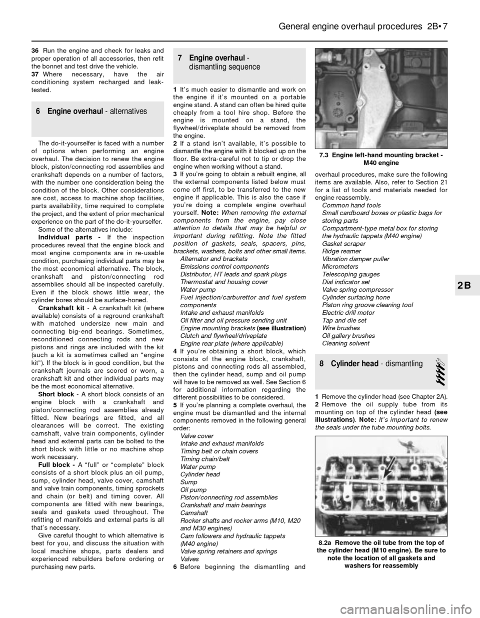
Engine mounting brackets (see illustration)
Clutch and flywheel/driveplate
Engine rear plate (where applicable)
4If you’re obtaining a short block, which
consists of the engine block, crankshaft,
pistons and connecting rods all assembled,
then the cylinder head, sump and oil pump
will have to be removed as well. See Section 6
for additional information regarding the
different possibilities to be considered.
5If you’re planning a complete overhaul, the
engine must be dismantled and the internal
components removed in the following general
order:
Valve cover
Intake and exhaust manifolds
Timing belt or chain covers
Timing chain/belt
Water pump
Cylinder head
Sump
Oil pump
Piston/connecting rod assemblies
Crankshaft and main bearings
Camshaft
Rocker shafts and rocker arms (M10, M20
and M30 engines)
Cam followers and hydraulic tappets
(M40 engine)
Valve spring retainers and springs
Valves
6Before beginning the dismantling andoverhaul procedures, make sure the following
items are available. Also, refer to Section 21
for a list of tools and materials needed for
engine reassembly.
Common hand tools
Small cardboard boxes or plastic bags for
storing parts
Compartment-type metal box for storing
the hydraulic tappets (M40 engine)
Gasket scraper
Ridge reamer
Vibration damper puller
Micrometers
Telescoping gauges
Dial indicator set
Valve spring compressor
Cylinder surfacing hone
Piston ring groove cleaning tool
Electric drill motor
Tap and die set
Wire brushes
Oil gallery brushes
Cleaning solvent
8 Cylinder head- dismantling
4
1Remove the cylinder head (see Chapter 2A).
2Remove the oil supply tube from its
mounting on top of the cylinder head (see
illustrations). Note:It’s important to renew
the seals under the tube mounting bolts.
General engine overhaul procedures 2B•7
7.3 Engine left-hand mounting bracket -
M40 engine
8.2a Remove the oil tube from the top of
the cylinder head (M10 engine). Be sure to
note the location of all gaskets and
washers for reassembly
2B