washer BMW 3 SERIES 1990 E30 User Guide
[x] Cancel search | Manufacturer: BMW, Model Year: 1990, Model line: 3 SERIES, Model: BMW 3 SERIES 1990 E30Pages: 228, PDF Size: 7.04 MB
Page 64 of 228
M10, M20 and M30 engines
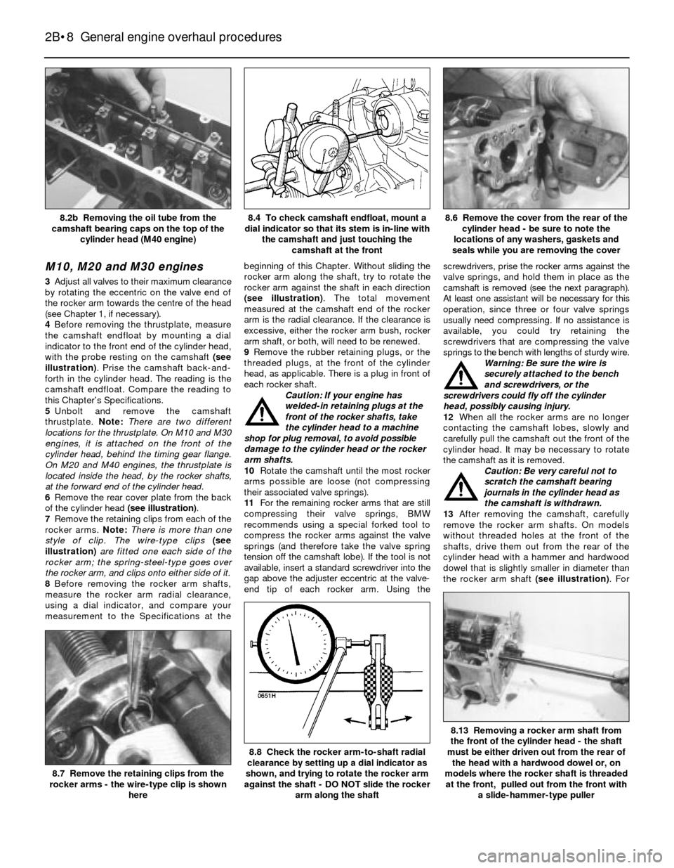
3Adjust all valves to their maximum clearance
by rotating the eccentric on the valve end of
the rocker arm towards the centre of the head
(see Chapter 1, if necessary).
4Before removing the thrustplate, measure
the camshaft endfloat by mounting a dial
indicator to the front end of the cylinder head,
with the probe resting on the camshaft (see
illustration). Prise the camshaft back-and-
forth in the cylinder head. The reading is the
camshaft endfloat. Compare the reading to
this Chapter’s Specifications.
5Unbolt and remove the camshaft
thrustplate. Note:There are two different
locations for the thrustplate. On M10 and M30
engines, it is attached on the front of the
cylinder head, behind the timing gear flange.
On M20 and M40 engines, the thrustplate is
located inside the head, by the rocker shafts,
at the forward end of the cylinder head.
6Remove the rear cover plate from the back
of the cylinder head (see illustration).
7Remove the retaining clips from each of the
rocker arms. Note:There is more than one
style of clip. The wire-type clips (see
illustration)are fitted one each side of the
rocker arm; the spring-steel-type goes over
the rocker arm, and clips onto either side of it.
8Before removing the rocker arm shafts,
measure the rocker arm radial clearance,
using a dial indicator, and compare your
measurement to the Specifications at thebeginning of this Chapter. Without sliding the
rocker arm along the shaft, try to rotate the
rocker arm against the shaft in each direction
(see illustration). The total movement
measured at the camshaft end of the rocker
arm is the radial clearance. If the clearance is
excessive, either the rocker arm bush, rocker
arm shaft, or both, will need to be renewed.
9Remove the rubber retaining plugs, or the
threaded plugs, at the front of the cylinder
head, as applicable. There is a plug in front of
each rocker shaft.
Caution: If your engine has
welded-in retaining plugs at the
front of the rocker shafts, take
the cylinder head to a machine
shop for plug removal, to avoid possible
damage to the cylinder head or the rocker
arm shafts.
10Rotate the camshaft until the most rocker
arms possible are loose (not compressing
their associated valve springs).
11For the remaining rocker arms that are still
compressing their valve springs, BMW
recommends using a special forked tool to
compress the rocker arms against the valve
springs (and therefore take the valve spring
tension off the camshaft lobe). If the tool is not
available, insert a standard screwdriver into the
gap above the adjuster eccentric at the valve-
end tip of each rocker arm. Using thescrewdrivers, prise the rocker arms against the
valve springs, and hold them in place as the
camshaft is removed (see the next paragraph).
At least one assistant will be necessary for this
operation, since three or four valve springs
usually need compressing. If no assistance is
available, you could try retaining the
screwdrivers that are compressing the valve
springs to the bench with lengths of sturdy wire.
Warning: Be sure the wire is
securely attached to the bench
and screwdrivers, or the
screwdrivers could fly off the cylinder
head, possibly causing injury.
12When all the rocker arms are no longer
contacting the camshaft lobes, slowly and
carefully pull the camshaft out the front of the
cylinder head. It may be necessary to rotate
the camshaft as it is removed.
Caution: Be very careful not to
scratch the camshaft bearing
journals in the cylinder head as
the camshaft is withdrawn.
13After removing the camshaft, carefully
remove the rocker arm shafts. On models
without threaded holes at the front of the
shafts, drive them out from the rear of the
cylinder head with a hammer and hardwood
dowel that is slightly smaller in diameter than
the rocker arm shaft (see illustration). For
2B•8 General engine overhaul procedures
8.13 Removing a rocker arm shaft from
the front of the cylinder head - the shaft
must be either driven out from the rear of
the head with a hardwood dowel or, on
models where the rocker shaft is threaded
at the front, pulled out from the front with
a slide-hammer-type puller
8.8 Check the rocker arm-to-shaft radial
clearance by setting up a dial indicator as
shown, and trying to rotate the rocker arm
against the shaft - DO NOT slide the rocker
arm along the shaft
8.7 Remove the retaining clips from the
rocker arms - the wire-type clip is shown
here
8.6 Remove the cover from the rear of the
cylinder head - be sure to note the
locations of any washers, gaskets and
seals while you are removing the cover8.4 To check camshaft endfloat, mount a
dial indicator so that its stem is in-line with
the camshaft and just touching the
camshaft at the front8.2b Removing the oil tube from the
camshaft bearing caps on the top of the
cylinder head (M40 engine)
Page 87 of 228
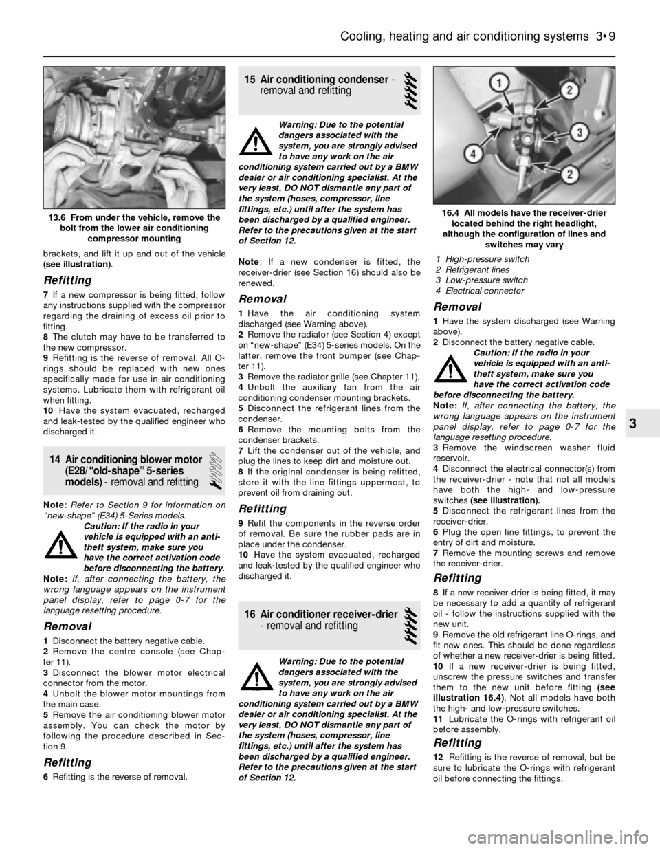
brackets, and lift it up and out of the vehicle
(see illustration).
Refitting
7If a new compressor is being fitted, follow
any instructions supplied with the compressor
regarding the draining of excess oil prior to
fitting.
8The clutch may have to be transferred to
the new compressor.
9Refitting is the reverse of removal. All O-
rings should be replaced with new ones
specifically made for use in air conditioning
systems. Lubricate them with refrigerant oil
when fitting.
10Have the system evacuated, recharged
and leak-tested by the qualified engineer who
discharged it.
14 Air conditioning blower motor
(E28/“old-shape” 5-series
models)- removal and refitting
1
Note: Refer to Section 9 for information on
“new-shape” (E34) 5-Series models.
Caution: If the radio in your
vehicle is equipped with an anti-
theft system, make sure you
have the correct activation code
before disconnecting the battery.
Note: If, after connecting the battery, the
wrong language appears on the instrument
panel display, refer to page 0-7 for the
language resetting procedure.
Removal
1Disconnect the battery negative cable.
2Remove the centre console (see Chap-
ter 11).
3Disconnect the blower motor electrical
connector from the motor.
4Unbolt the blower motor mountings from
the main case.
5Remove the air conditioning blower motor
assembly. You can check the motor by
following the procedure described in Sec-
tion 9.
Refitting
6Refitting is the reverse of removal.
15 Air conditioning condenser-
removal and refitting
5
Warning: Due to the potential
dangers associated with the
system, you are strongly advised
to have any work on the air
conditioning system carried out by a BMW
dealer or air conditioning specialist. At the
very least, DO NOT dismantle any part of
the system (hoses, compressor, line
fittings, etc.) until after the system has
been discharged by a qualified engineer.
Refer to the precautions given at the start
of Section 12.
Note: If a new condenser is fitted, the
receiver-drier (see Section 16) should also be
renewed.
Removal
1Have the air conditioning system
discharged (see Warning above).
2Remove the radiator (see Section 4) except
on “new-shape” (E34) 5-series models. On the
latter, remove the front bumper (see Chap-
ter 11).
3Remove the radiator grille (see Chapter 11).
4Unbolt the auxiliary fan from the air
conditioning condenser mounting brackets.
5Disconnect the refrigerant lines from the
condenser.
6Remove the mounting bolts from the
condenser brackets.
7Lift the condenser out of the vehicle, and
plug the lines to keep dirt and moisture out.
8If the original condenser is being refitted,
store it with the line fittings uppermost, to
prevent oil from draining out.
Refitting
9Refit the components in the reverse order
of removal. Be sure the rubber pads are in
place under the condenser.
10Have the system evacuated, recharged
and leak-tested by the qualified engineer who
discharged it.
16 Air conditioner receiver-drier
- removal and refitting
5
Warning: Due to the potential
dangers associated with the
system, you are strongly advised
to have any work on the air
conditioning system carried out by a BMW
dealer or air conditioning specialist. At the
very least, DO NOT dismantle any part of
the system (hoses, compressor, line
fittings, etc.) until after the system has
been discharged by a qualified engineer.
Refer to the precautions given at the start
of Section 12.
Removal
1Have the system discharged (see Warning
above).
2Disconnect the battery negative cable.
Caution: If the radio in your
vehicle is equipped with an anti-
theft system, make sure you
have the correct activation code
before disconnecting the battery.
Note: If, after connecting the battery, the
wrong language appears on the instrument
panel display, refer to page 0-7 for the
language resetting procedure.
3Remove the windscreen washer fluid
reservoir.
4Disconnect the electrical connector(s) from
the receiver-drier - note that not all models
have both the high- and low-pressure
switches (see illustration).
5Disconnect the refrigerant lines from the
receiver-drier.
6Plug the open line fittings, to prevent the
entry of dirt and moisture.
7Remove the mounting screws and remove
the receiver-drier.
Refitting
8If a new receiver-drier is being fitted, it may
be necessary to add a quantity of refrigerant
oil - follow the instructions supplied with the
new unit.
9Remove the old refrigerant line O-rings, and
fit new ones. This should be done regardless
of whether a new receiver-drier is being fitted.
10If a new receiver-drier is being fitted,
unscrew the pressure switches and transfer
them to the new unit before fitting (see
illustration 16.4). Not all models have both
the high- and low-pressure switches.
11Lubricate the O-rings with refrigerant oil
before assembly.
Refitting
12Refitting is the reverse of removal, but be
sure to lubricate the O-rings with refrigerant
oil before connecting the fittings.
Cooling, heating and air conditioning systems 3•9
16.4 All models have the receiver-drier
located behind the right headlight,
although the configuration of lines and
switches may vary
3
13.6 From under the vehicle, remove the
bolt from the lower air conditioning
compressor mounting
1 High-pressure switch
2 Refrigerant lines
3 Low-pressure switch
4 Electrical connector
Page 121 of 228
Refer to the information on page 0-7 at the
front of this manual before detaching the
cable.
Note: If, after connecting the battery, the
wrong language appears on the instrument
panel display, refer to page 0-7 for the
language resetting procedure.
1Disconnect the battery negative cable.
Bosch alternator
2Remove the voltage regulator from the back
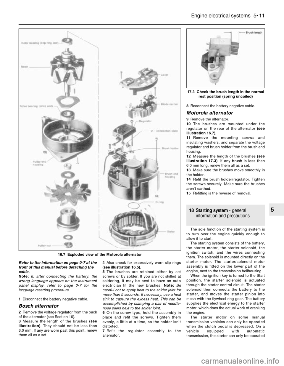
of the alternator (see Section 16).
3Measure the length of the brushes (see
illustration). They should not be less than
6.0 mm. If any are worn past this point, renew
them all as a set. 4Also check for excessively worn slip rings
(see illustration 16.5).
5The brushes are retained either by set
screws or by solder. If you are not skilled at
soldering, it may be best to have an auto
electrician fit the new brushes. Note: Be
careful not to apply heat to the solder joint for
more than 5 seconds. If necessary, use a heat
sink to capture the excess heat. This can be
accomplished by clamping a pair of needle-
nose pliers next to the solder joint.
6On the screw type, hold the assembly in
place and refit the screws. Tighten them
evenly, a little at a time, so the holder isn’t
distorted.
7Refit the regulator assembly to the
alternator.8Reconnect the battery negative cable.
Motorola alternator
9Remove the alternator.
10The brushes are mounted under the
regulator on the rear of the alternator (see
illustration 16.7).
11Remove the mounting screws and
insulating washers, and separate the voltage
regulator and brush holder from the brush end
housing.
12Measure the length of the brushes (see
illustration 17.3). If any brush is less then
6.0 mm long, renew them all as a set.
13Make sure the brushes move smoothly in
the holder.
14Refit the brush holder/regulator. Tighten
the screws securely. Make sure the brushes
aren’t earthed.
15Refitting is the reverse of removal.
18 Starting system- general
information and precautions
The sole function of the starting system is
to turn over the engine quickly enough to
allow it to start.
The starting system consists of the battery,
the starter motor, the starter solenoid, the
ignition switch, and the wires connecting
them. The solenoid is mounted directly on the
starter motor. The starter/solenoid motor
assembly is fitted on the lower part of the
engine, next to the transmission bellhousing.
When the ignition key is turned to the Start
position, the starter solenoid is actuated
through the starter control circuit. The starter
solenoid then connects the battery to the
starter, and moves the starter pinion into
mesh with the flywheel ring gear. The battery
supplies the electrical energy to the starter
motor, which does the actual work of cranking
the engine.
The starter motor on some manual
transmission vehicles can only be operated
when the clutch pedal is depressed. On a
vehicle equipped with automatic
transmission, the starter can only be operated
Engine electrical systems 5•11
17.3 Check the brush length in the normal
rest position (spring uncoiled)
5
16.7 Exploded view of the Motorola alternator
Page 133 of 228
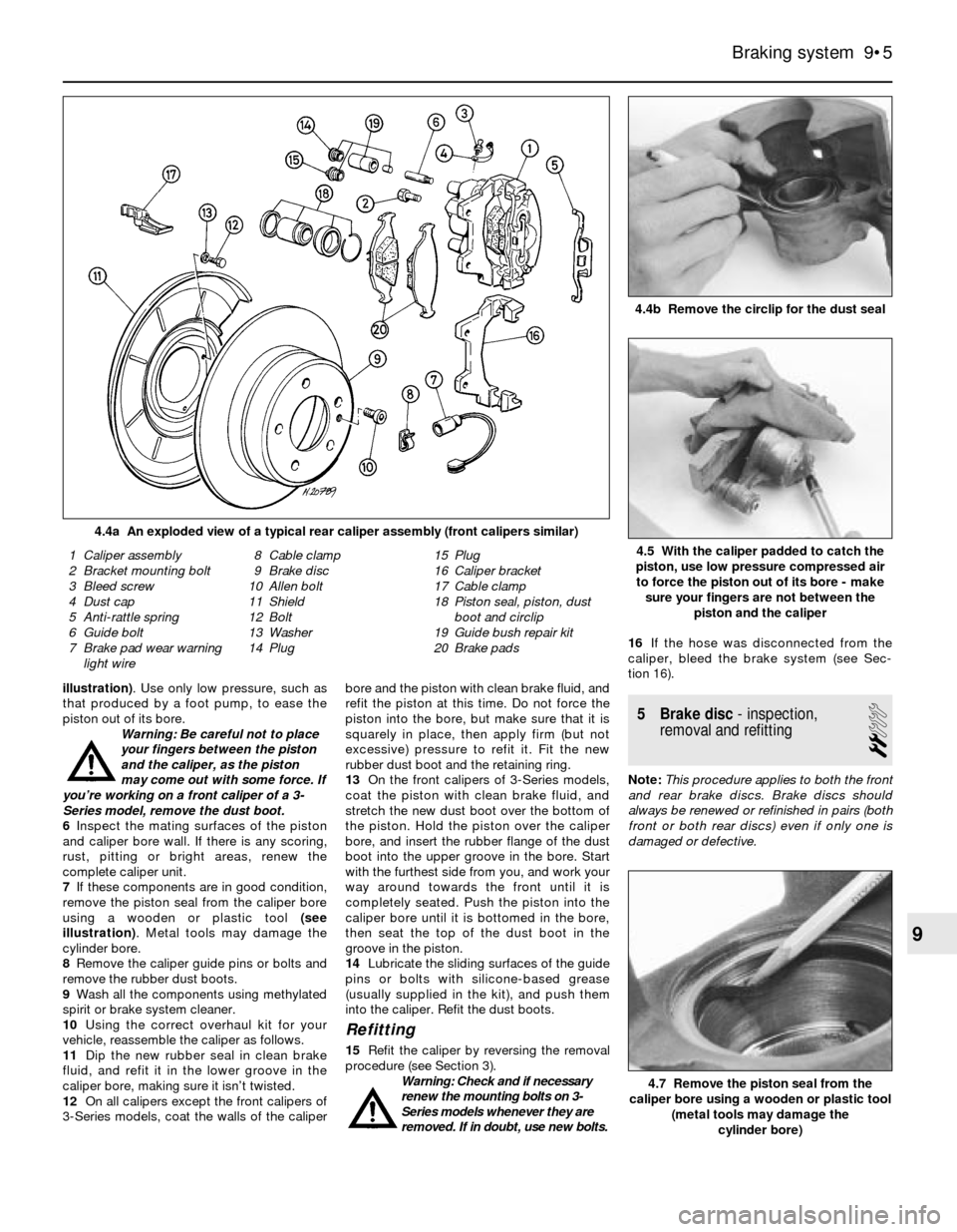
illustration). Use only low pressure, such as
that produced by a foot pump, to ease the
piston out of its bore.
Warning: Be careful not to place
your fingers between the piston
and the caliper, as the piston
may come out with some force. If
you’re working on a front caliper of a 3-
Series model, remove the dust boot.
6Inspect the mating surfaces of the piston
and caliper bore wall. If there is any scoring,
rust, pitting or bright areas, renew the
complete caliper unit.
7If these components are in good condition,
remove the piston seal from the caliper bore
using a wooden or plastic tool (see
illustration). Metal tools may damage the
cylinder bore.
8Remove the caliper guide pins or bolts and
remove the rubber dust boots.
9Wash all the components using methylated
spirit or brake system cleaner.
10Using the correct overhaul kit for your
vehicle, reassemble the caliper as follows.
11Dip the new rubber seal in clean brake
fluid, and refit it in the lower groove in the
caliper bore, making sure it isn’t twisted.
12On all calipers except the front calipers of
3-Series models, coat the walls of the caliperbore and the piston with clean brake fluid, and
refit the piston at this time. Do not force the
piston into the bore, but make sure that it is
squarely in place, then apply firm (but not
excessive) pressure to refit it. Fit the new
rubber dust boot and the retaining ring.
13On the front calipers of 3-Series models,
coat the piston with clean brake fluid, and
stretch the new dust boot over the bottom of
the piston. Hold the piston over the caliper
bore, and insert the rubber flange of the dust
boot into the upper groove in the bore. Start
with the furthest side from you, and work your
way around towards the front until it is
completely seated. Push the piston into the
caliper bore until it is bottomed in the bore,
then seat the top of the dust boot in the
groove in the piston.
14Lubricate the sliding surfaces of the guide
pins or bolts with silicone-based grease
(usually supplied in the kit), and push them
into the caliper. Refit the dust boots.
Refitting
15Refit the caliper by reversing the removal
procedure (see Section 3).
Warning: Check and if necessary
renew the mounting bolts on 3-
Series models whenever they are
removed. If in doubt, use new bolts.16If the hose was disconnected from the
caliper, bleed the brake system (see Sec-
tion 16).
5 Brake disc- inspection,
removal and refitting
2
Note:This procedure applies to both the front
and rear brake discs. Brake discs should
always be renewed or refinished in pairs (both
front or both rear discs) even if only one is
damaged or defective.
Braking system 9•5
4.4b Remove the circlip for the dust seal
4.4a An exploded view of a typical rear caliper assembly (front calipers similar)
4.7 Remove the piston seal from the
caliper bore using a wooden or plastic tool
(metal tools may damage the
cylinder bore)
1 Caliper assembly
2 Bracket mounting bolt
3 Bleed screw
4 Dust cap
5 Anti-rattle spring
6 Guide bolt
7 Brake pad wear warning
light wire8 Cable clamp
9 Brake disc
10 Allen bolt
11 Shield
12 Bolt
13 Washer
14 Plug15 Plug
16 Caliper bracket
17 Cable clamp
18 Piston seal, piston, dust
boot and circlip
19 Guide bush repair kit
20 Brake pads4.5 With the caliper padded to catch the
piston, use low pressure compressed air
to force the piston out of its bore - make
sure your fingers are not between the
piston and the caliper
9
Page 148 of 228
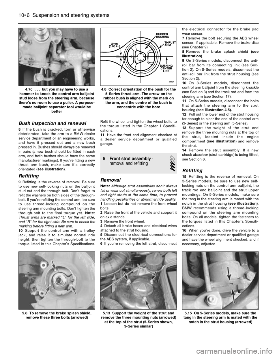
Bush inspection and renewal
8If the bush is cracked, torn or otherwise
deteriorated, take the arm to a BMW dealer
service department or an engineering works,
and have it pressed out and a new bush
pressed in. Bushes should always be renewed
in pairs (a new bush should be fitted in each
arm, and both bushes should have the same
manufacturer markings). If you’re fitting a new
thrust arm bush, make sure it’s correctly
orientated (see illustration).
Refitting
9Refitting is the reverse of removal. Be sure
to use new self-locking nuts on the balljoint
stud nut and the through-bolt. Don’t forget to
refit the washers on both sides of the through-
bolt. If you’re refitting the control arm, be sure
to use thread-locking compound on the
steering arm mounting bolts. Don’t tighten the
through-bolt to the final torque yet. Note:
Thrust arms are marked “L” for the left side,
and “R” for the right side. Be sure to check the
marking before fitting a new arm.
10Support the control arm with a trolley
jack, and raise it to simulate normal ride
height, then tighten the through-bolt to the
torque listed in this Chapter’s Specifications.Refit the wheel and tighten the wheel bolts to
the torque listed in the Chapter 1 Specifi-
cations.
11Have the front end alignment checked at
a dealer service department or qualified
garage.
5 Front strut assembly-
removal and refitting
3
Removal
Note:Although strut assemblies don’t always
fail or wear out simultaneously, renew both left
and right struts at the same time, to prevent
handling peculiarities or abnormal ride quality.
1Loosen but do not remove the front wheel
bolts.
2Raise the front of the vehicle and support it
on axle stands.
3Remove the front wheel.
4Detach all brake hoses and electrical wires
attached to the strut housing.
5Disconnect the electrical connections for
the ABS system, if applicable.
6If you’re removing the left strut, disconnectthe electrical connector for the brake pad
wear sensor.
7Remove the bolt securing the ABS wheel
sensor, if applicable. Remove the brake disc
(see Chapter 9).
8Remove the brake splash shield (see
illustration).
9On 3-Series models, disconnect the anti-
roll bar from its connecting link (see Sec-
tion 2). On 5-Series models, disconnect the
anti-roll bar link from the strut housing (see
Section 2).
10On 3-Series models, disconnect the
control arm balljoint from the steering knuckle
(see Section 3) and the track rod end from the
steering arm (see Section 17).
11On 5-Series models, disconnect the bolts
that attach the steering arm to the strut
housing (see illustration 4.5).
12Pull out the lower end of the strut housing
far enough to clear the end of the control arm
(3-Series) or the steering arm (5-Series).
13Support the weight of the strut and
remove the three mounting nuts at the top of
the strut, located inside the engine
compartment (see illustration)and remove
the strut.
14Remove the strut assembly. If a new
shock absorber (strut cartridge) is being fitted,
see Section 6.
Refitting
15Refitting is the reverse of removal. On
3-Series models, be sure to use new self-
locking nuts on the control arm balljoint, the
track rod end balljoint and the strut upper
mountings. On 5-Series models, make sure
the tang in the steering arm is mated with the
notch in the strut housing (see illustration).
BMW recommends using a thread-locking
compound on the steering arm mounting
bolts. On all models, tighten the fasteners to
the torques listed in this Chapter’s Specifi-
cations.
16When you’re done, drive the vehicle to a
dealer service department or qualified garage
and have the wheel alignment checked, and if
necessary, adjusted.
10•6 Suspension and steering systems
5.15 On 5-Series models, make sure the
tang in the steering arm is mated with the
notch in the strut housing (arrowed)5.13 Support the weight of the strut and
remove the three mounting nuts (arrowed)
at the top of the strut (5-Series shown,
3-Series similar)5.8 To remove the brake splash shield,
remove these three bolts (arrowed)
4.8 Correct orientation of the bush for the
5-Series thrust arm. The arrow on the
rubber bush is aligned with the mark on
the arm, and the centre of the bush is
concentric with the bore4.7c . . . but you may have to use a
hammer to knock the control arm balljoint
stud loose from the steering arm, because
there’s no room to use a puller. A purpose-
made balljoint separator tool would be
better
Page 149 of 228
6 Strut or shock absorber/coil
spring- renewal
4
Note:This section applies to all front strut
assemblies and, on 5-Series models, the rear
coil-over shock absorber assemblies.
1If the struts, shock absorbers or coil springs
exhibit the telltale signs of wear (leaking fluid,
loss of damping capability, chipped, sagging
or cracked coil springs) explore all options
before beginning any work. Strut or shock
absorber assemblies complete with springs
may be available on an exchange basis, which
eliminates much time and work. Whichever
route you choose to take, check on the cost
and availability of parts before dismantling the
vehicle.
Warning: Dismantling a strut or
coil-over shock absorber
assembly is a potentially
dangerous undertaking, and
utmost attention must be directed to the
job, or serious injury may result. Use only a
high-quality spring compressor, and
carefully follow the manufacturer’s
instructions supplied with the tool. After
removing the coil spring from the strut
assembly, set it aside in a safe, isolated
area.
2Remove the strut or shock absorber
assembly (see Section 5 or 11). Mount the
assembly in a vice. Line the vice jaws with
wood or rags to prevent damage to the unit,
and don’t tighten the vice excessively.
3Following the tool manufacturer’s
instructions, fit the spring compressor (these
can be obtained at most car accessory shops,
or it may be possible to hire one) on the
spring, and compress it sufficiently to relieve
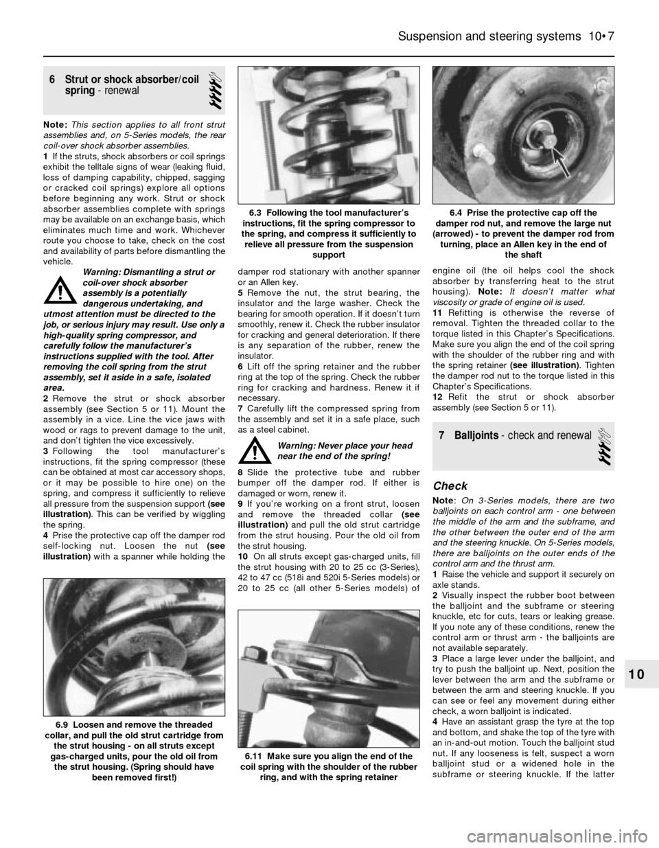
all pressure from the suspension support (see
illustration). This can be verified by wiggling
the spring.
4Prise the protective cap off the damper rod
self-locking nut. Loosen the nut (see
illustration)with a spanner while holding thedamper rod stationary with another spanner
or an Allen key.
5Remove the nut, the strut bearing, the
insulator and the large washer. Check the
bearing for smooth operation. If it doesn’t turn
smoothly, renew it. Check the rubber insulator
for cracking and general deterioration. If there
is any separation of the rubber, renew the
insulator.
6Lift off the spring retainer and the rubber
ring at the top of the spring. Check the rubber
ring for cracking and hardness. Renew it if
necessary.
7Carefully lift the compressed spring from
the assembly and set it in a safe place, such
as a steel cabinet.
Warning: Never place your head
near the end of the spring!
8Slide the protective tube and rubber
bumper off the damper rod. If either is
damaged or worn, renew it.
9If you’re working on a front strut, loosen
and remove the threaded collar (see
illustration)and pull the old strut cartridge
from the strut housing. Pour the old oil from
the strut housing.
10On all struts except gas-charged units, fill
the strut housing with 20 to 25 cc (3-Series),
42 to 47 cc (518i and 520i 5-Series models) or
20 to 25 cc (all other 5-Series models) ofengine oil (the oil helps cool the shock
absorber by transferring heat to the strut
housing). Note:It doesn’t matter what
viscosity or grade of engine oil is used.
11Refitting is otherwise the reverse of
removal. Tighten the threaded collar to the
torque listed in this Chapter’s Specifications.
Make sure you align the end of the coil spring
with the shoulder of the rubber ring and with
the spring retainer (see illustration). Tighten
the damper rod nut to the torque listed in this
Chapter’s Specifications.
12Refit the strut or shock absorber
assembly (see Section 5 or 11).
7 Balljoints- check and renewal
3
Check
Note:On 3-Series models, there are two
balljoints on each control arm - one between
the middle of the arm and the subframe, and
the other between the outer end of the arm
and the steering knuckle. On 5-Series models,
there are balljoints on the outer ends of the
control arm and the thrust arm.
1Raise the vehicle and support it securely on
axle stands.
2Visually inspect the rubber boot between
the balljoint and the subframe or steering
knuckle, etc for cuts, tears or leaking grease.
If you note any of these conditions, renew the
control arm or thrust arm - the balljoints are
not available separately.
3Place a large lever under the balljoint, and
try to push the balljoint up. Next, position the
lever between the arm and the subframe or
between the arm and steering knuckle. If you
can see or feel any movement during either
check, a worn balljoint is indicated.
4Have an assistant grasp the tyre at the top
and bottom, and shake the top of the tyre with
an in-and-out motion. Touch the balljoint stud
nut. If any looseness is felt, suspect a worn
balljoint stud or a widened hole in the
subframe or steering knuckle. If the latter
Suspension and steering systems 10•7
6.4 Prise the protective cap off the
damper rod nut, and remove the large nut
(arrowed) - to prevent the damper rod from
turning, place an Allen key in the end of
the shaft6.3 Following the tool manufacturer’s
instructions, fit the spring compressor to
the spring, and compress it sufficiently to
relieve all pressure from the suspension
support
6.11 Make sure you align the end of the
coil spring with the shoulder of the rubber
ring, and with the spring retainer
6.9 Loosen and remove the threaded
collar, and pull the old strut cartridge from
the strut housing - on all struts except
gas-charged units, pour the old oil from
the strut housing. (Spring should have
been removed first!)
10
Page 152 of 228
4Inspect and, if necessary, renew any worn
or defective bolts, washers, bushes or links.
Refitting
5Refitting is the reverse of removal. Tighten
all fasteners securely.
13 Rear trailing arms (3-Series)
- removal and refitting
3
Removal
1Loosen the wheel bolts, then chock the
front wheels. Raise the rear of the vehicle, and
support it securely on axle stands. Remove
the wheel(s).
2Remove the driveshaft (see Chapter 8), or
disconnect it from the final drive output
flange.
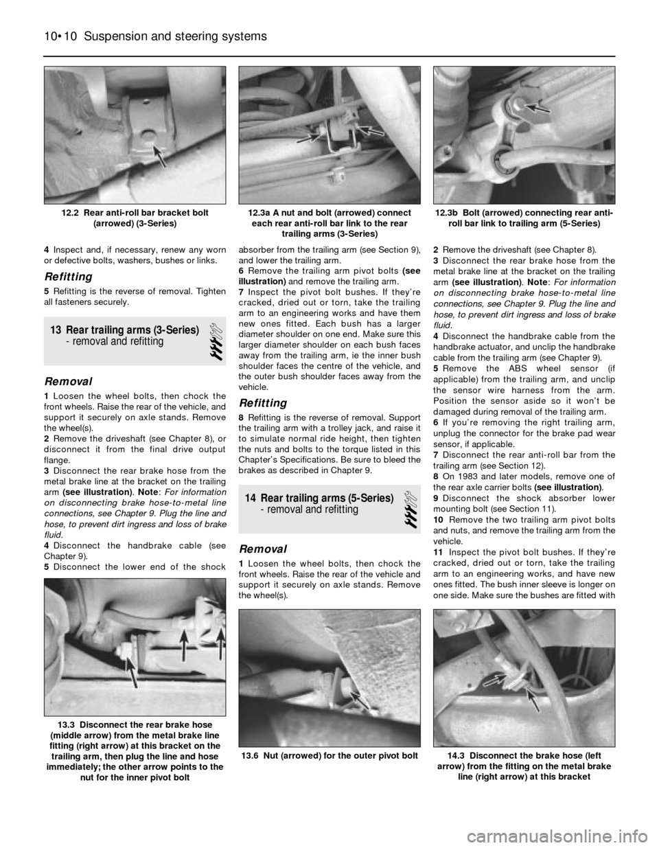
3Disconnect the rear brake hose from the
metal brake line at the bracket on the trailing
arm (see illustration). Note: For information
on disconnecting brake hose-to-metal line
connections, see Chapter 9. Plug the line and
hose, to prevent dirt ingress and loss of brake
fluid.
4Disconnect the handbrake cable (see
Chapter 9).
5Disconnect the lower end of the shockabsorber from the trailing arm (see Section 9),
and lower the trailing arm.
6Remove the trailing arm pivot bolts (see
illustration)and remove the trailing arm.
7Inspect the pivot bolt bushes. If they’re
cracked, dried out or torn, take the trailing
arm to an engineering works and have them
new ones fitted. Each bush has a larger
diameter shoulder on one end. Make sure this
larger diameter shoulder on each bush faces
away from the trailing arm, ie the inner bush
shoulder faces the centre of the vehicle, and
the outer bush shoulder faces away from the
vehicle.Refitting
8Refitting is the reverse of removal. Support
the trailing arm with a trolley jack, and raise it
to simulate normal ride height, then tighten
the nuts and bolts to the torque listed in this
Chapter’s Specifications. Be sure to bleed the
brakes as described in Chapter 9.
14 Rear trailing arms (5-Series)
- removal and refitting
3
Removal
1Loosen the wheel bolts, then chock the
front wheels. Raise the rear of the vehicle and
support it securely on axle stands. Remove
the wheel(s).2Remove the driveshaft (see Chapter 8).
3Disconnect the rear brake hose from the
metal brake line at the bracket on the trailing
arm (see illustration). Note: For information
on disconnecting brake hose-to-metal line
connections, see Chapter 9. Plug the line and
hose, to prevent dirt ingress and loss of brake
fluid.
4Disconnect the handbrake cable from the
handbrake actuator, and unclip the handbrake
cable from the trailing arm (see Chapter 9).
5Remove the ABS wheel sensor (if
applicable) from the trailing arm, and unclip
the sensor wire harness from the arm.
Position the sensor aside so it won’t be
damaged during removal of the trailing arm.
6If you’re removing the right trailing arm,
unplug the connector for the brake pad wear
sensor, if applicable.
7Disconnect the rear anti-roll bar from the
trailing arm (see Section 12).
8On 1983 and later models, remove one of
the rear axle carrier bolts (see illustration).
9Disconnect the shock absorber lower
mounting bolt (see Section 11).
10Remove the two trailing arm pivot bolts
and nuts, and remove the trailing arm from the
vehicle.
11Inspect the pivot bolt bushes. If they’re
cracked, dried out or torn, take the trailing
arm to an engineering works, and have new
ones fitted. The bush inner sleeve is longer on
one side. Make sure the bushes are fitted with
10•10 Suspension and steering systems
14.3 Disconnect the brake hose (left
arrow) from the fitting on the metal brake
line (right arrow) at this bracket13.6 Nut (arrowed) for the outer pivot bolt
13.3 Disconnect the rear brake hose
(middle arrow) from the metal brake line
fitting (right arrow) at this bracket on the
trailing arm, then plug the line and hose
immediately; the other arrow points to the
nut for the inner pivot bolt
12.3b Bolt (arrowed) connecting rear anti-
roll bar link to trailing arm (5-Series)12.3a A nut and bolt (arrowed) connect
each rear anti-roll bar link to the rear
trailing arms (3-Series)12.2 Rear anti-roll bar bracket bolt
(arrowed) (3-Series)
Page 156 of 228
syringe or hand pump, empty the power
steering fluid reservoir.
4On power steering models, remove the
banjo bolts and disconnect the power
steering pressure and return lines from the
steering gear. Place a container under the
lines to catch spilled fluid. Plug the lines to
prevent excessive fluid loss and
contamination. Discard the sealing washers
(new ones should be used when
reassembling).
5Disconnect the track rod ends from the
steering arms (see Section 17).
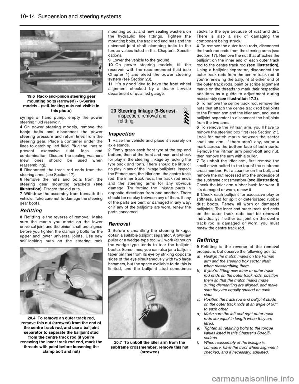
6Remove the nuts and bolts from the
steering gear mounting brackets (see
illustration). Discard the old nuts.
7Withdraw the assembly from beneath the
vehicle. Take care not to damage the steering
gear boots.
Refitting
8Refitting is the reverse of removal. Make
sure the marks you made on the lower
universal joint and the pinion shaft are aligned
before you tighten the clamping bolts for the
upper and lower universal joints. Use new
self-locking nuts on the steering rackmounting bolts, and new sealing washers on
the hydraulic line fittings. Tighten the
mounting bolts, the track rod end nuts and the
universal joint shaft clamping bolts to the
torque values listed in this Chapter’s Specifi-
cations.
9Lower the vehicle to the ground.
10On power steering models, fill the
reservoir with the recommended fluid (see
Chapter 1) and bleed the power steering
system (see Section 23).
11It’s a good idea to have the front wheel
alignment checked by a dealer service
department or qualified garage.
20 Steering linkage (5-Series)-
inspection, removal and
refitting
4
Inspection
1Raise the vehicle and place it securely on
axle stands.
2Firmly grasp each front tyre at the top and
bottom, then at the front and rear, and check
for play in the steering linkage by rocking the
tyre back and forth. There should be little or
no play in any of the linkage balljoints. Inspect
the Pitman arm, the idler arm, the centre track
rod, the inner track rods, the track rod ends
and the steering arms for any obvious
damage. Try forcing the linkage parts in
opposite directions from one another. There
should be no play between any of them. If any
of the parts are bent or damaged in any way,
or if any of the balljoints are worn, renew the
parts concerned.
Removal
3Before dismantling the steering linkage,
obtain a suitable balljoint separator. A two-jaw
puller or a wedge-type tool will work (although
the wedge-type tends to tear the balljoint
boots). Sometimes, you can also jar a balljoint
taper pin free from its eye by striking opposite
sides of the eye simultaneously with two large
hammers, but the space available to do this is
limited, and the balljoint stud sometimessticks to the eye because of rust and dirt.
There is also a risk of damaging the
component being struck.
4To remove the outer track rods, disconnect
the track rod ends from the steering arms (see
Section 17). Remove the nut that attaches the
balljoint on the inner end of each outer track
rod to the centre track rod (see illustration).
Using a balljoint separator, disconnect the
outer track rods from the centre track rod. If
you’re renewing the balljoint at either end of
the outer track rods, paint or scribe alignment
marks on the threads to mark their respective
positions as a guide to adjustment during
reassembly (see illustration 17.3).
5To remove the centre track rod, remove the
nuts that attach the centre track rod balljoints
to the Pitman arm and the idler arm, and use a
balljoint separator to disconnect the balljoints
from the two arms.
6To remove the Pitman arm, you’ll have to
remove the steering box first (see Section 21).
Look for match marks between the sector
shaft and arm. If there aren’t any, scribe a
mark across the bottom face of both parts.
Remove the Pitman arm pinch-bolt and nut,
then remove the arm with a puller.
7To unbolt the idler arm, first remove the
small cover bolted to the top of the subframe
crossmember. Put a spanner on the bolt, and
remove the nut recessed into the underside of
the subframe crossmember (see illustration).
Check the idler arm rubber bush for wear. If
it’s damaged or worn, renew it.
8Check each balljoint for excessive play or
stiffness, and for split or deteriorated rubber
dust boots. Renew all worn or damaged
balljoints. The inner and outer track rod ends
on the outer track rods can be renewed
individually; if either balljoint on the centre
track rod is damaged or worn, you must
renew the centre track rod.
Refitting
9Refitting is the reverse of the removal
procedure, but observe the following points:
a) Realign the match marks on the Pitman
arm and the steering box sector shaft
when reassembling them.
b) If you’re fitting new inner or outer track
rod ends on the outer track rods, position
them so that the match marks made
during dismantling are aligned, and make
sure they are equally spaced on each
side.
c) Position the track rod end balljoint studs
on the outer track rods at an angle of 90°
to each other.
d) Make sure the left and right outer track
rods are equal in length when they are
fitted.
e) Tighten all retaining bolts to the torque
values listed in this Chapter’s Specifi-
cations.
f) When reassembly of the linkage is
complete, have the front wheel alignment
checked, and if necessary, adjusted.
10•14 Suspension and steering systems
20.7 To unbolt the idler arm from the
subframe crossmember, remove this nut
(arrowed)
20.4 To remove an outer track rod,
remove this nut (arrowed) from the end of
the centre track rod, and use a balljoint
separator to separate the balljoint stud
from the centre track rod (if you’re
renewing the inner track rod end, mark the
threads with paint before loosening the
clamp bolt and nut)
19.6 Rack-and-pinion steering gear
mounting bolts (arrowed) - 3-Series
models - (self-locking nuts not visible in
this photo)
Page 157 of 228
21 Steering box (5-Series)-
removal and refitting
4
Removal
Note:If you find that the steering box is
defective, it is not recommended that you
overhaul it. Because of the special tools
needed to do the job, it is best to let your
dealer service department overhaul it for you
(otherwise, fit a new unit). Removal and
refitting the steering box is outlined here.
1On 5-Series E28 (“old-shape”) models,
discharge the hydraulic system by depressing
the brake pedal about 20 times.
2Using a large syringe or hand pump, empty
the power steering fluid reservoir (see Chap-
ter 1).
3Raise the front of the vehicle and support it
securely on axle stands.
4Support the front of the engine with a trolley
jack. Place a block of wood between the jack
head and the sump to protect the sump from
damage.
5Remove the pivot bolts from the inner ends
of the front control arms (see Section 4).
6Remove the nuts from the left and right
engine mountings (see Chapter 2).
7Remove the mounting bolts (two on each
side on earlier models, three on each side on
later models) from the subframe crossmember
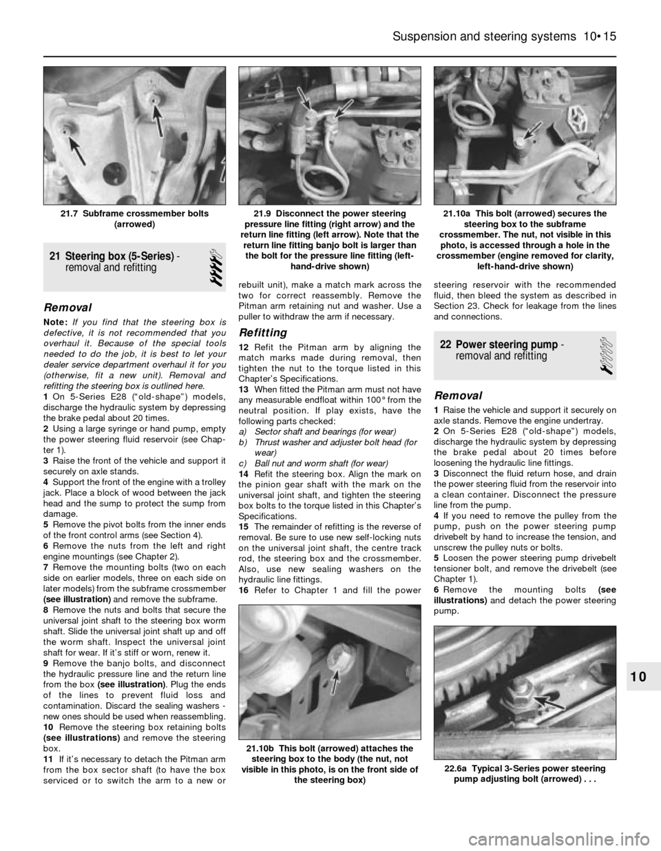
(see illustration)and remove the subframe.
8Remove the nuts and bolts that secure the
universal joint shaft to the steering box worm
shaft. Slide the universal joint shaft up and off
the worm shaft. Inspect the universal joint
shaft for wear. If it’s stiff or worn, renew it.
9Remove the banjo bolts, and disconnect
the hydraulic pressure line and the return line
from the box (see illustration). Plug the ends
of the lines to prevent fluid loss and
contamination. Discard the sealing washers -
new ones should be used when reassembling.
10Remove the steering box retaining bolts
(see illustrations)and remove the steering
box.
11If it’s necessary to detach the Pitman arm
from the box sector shaft (to have the box
serviced or to switch the arm to a new orrebuilt unit), make a match mark across the
two for correct reassembly. Remove the
Pitman arm retaining nut and washer. Use a
puller to withdraw the arm if necessary.
Refitting
12Refit the Pitman arm by aligning the
match marks made during removal, then
tighten the nut to the torque listed in this
Chapter’s Specifications.
13When fitted the Pitman arm must not have
any measurable endfloat within 100° from the
neutral position. If play exists, have the
following parts checked:
a) Sector shaft and bearings (for wear)
b) Thrust washer and adjuster bolt head (for
wear)
c) Ball nut and worm shaft (for wear)
14Refit the steering box. Align the mark on
the pinion gear shaft with the mark on the
universal joint shaft, and tighten the steering
box bolts to the torque listed in this Chapter’s
Specifications.
15The remainder of refitting is the reverse of
removal. Be sure to use new self-locking nuts
on the universal joint shaft, the centre track
rod, the steering box and the crossmember.
Also, use new sealing washers on the
hydraulic line fittings.
16Refer to Chapter 1 and fill the powersteering reservoir with the recommended
fluid, then bleed the system as described in
Section 23. Check for leakage from the lines
and connections.22 Power steering pump-
removal and refitting
1
Removal
1Raise the vehicle and support it securely on
axle stands. Remove the engine undertray.
2On 5-Series E28 (“old-shape”) models,
discharge the hydraulic system by depressing
the brake pedal about 20 times before
loosening the hydraulic line fittings.
3Disconnect the fluid return hose, and drain
the power steering fluid from the reservoir into
a clean container. Disconnect the pressure
line from the pump.
4If you need to remove the pulley from the
pump, push on the power steering pump
drivebelt by hand to increase the tension, and
unscrew the pulley nuts or bolts.
5Loosen the power steering pump drivebelt
tensioner bolt, and remove the drivebelt (see
Chapter 1).
6Remove the mounting bolts (see
illustrations)and detach the power steering
pump.
Suspension and steering systems 10•15
21.10a This bolt (arrowed) secures the
steering box to the subframe
crossmember. The nut, not visible in this
photo, is accessed through a hole in the
crossmember (engine removed for clarity,
left-hand-drive shown)21.9 Disconnect the power steering
pressure line fitting (right arrow) and the
return line fitting (left arrow). Note that the
return line fitting banjo bolt is larger than
the bolt for the pressure line fitting (left-
hand-drive shown)21.7 Subframe crossmember bolts
(arrowed)
22.6a Typical 3-Series power steering
pump adjusting bolt (arrowed) . . .
21.10b This bolt (arrowed) attaches the
steering box to the body (the nut, not
visible in this photo, is on the front side of
the steering box)
10
Page 163 of 228
7 Hinges and locks-
maintenance
1
Every six months or so, the hinges and lock
assemblies on the doors, bonnet and the boot
lid/tailgate should be given a few drops of
light oil or lock lubricant. The door or tailgate
lock strikers should also be lubricated with a
thin coat of grease, to reduce wear and
ensure free movement.
8 Fixed glass- renewal
5
Renewal of the windscreen and fixed glass
requires the use of special fast-setting
adhesive materials, and some specialised
tools and techniques. These operations
should be left to a dealer service department
or windscreen specialist.
9 Radiator grille-
removal and refitting
1
3-Series
1Detach the clips along the top of the grille
(see illustration).2Remove the screws, and lift the centre and
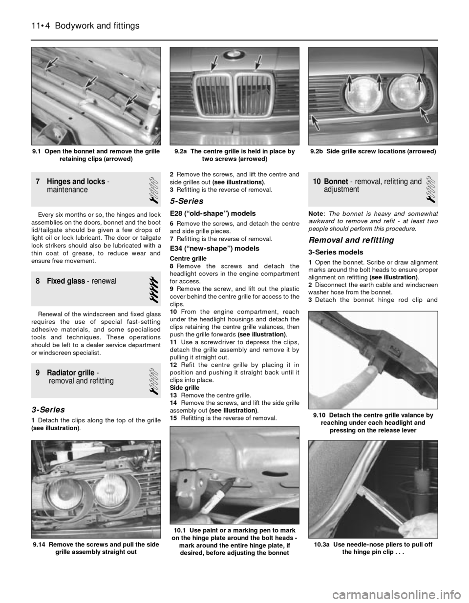
side grilles out (see illustrations).
3Refitting is the reverse of removal.
5-Series
E28 (“old-shape”) models
6Remove the screws, and detach the centre
and side grille pieces.
7Refitting is the reverse of removal.
E34 (“new-shape”) models
Centre grille
8Remove the screws and detach the
headlight covers in the engine compartment
for access.
9Remove the screw, and lift out the plastic
cover behind the centre grille for access to the
clips.
10From the engine compartment, reach
under the headlight housings and detach the
clips retaining the centre grille valances, then
push the grille forwards (see illustration).
11Use a screwdriver to depress the clips,
detach the grille assembly and remove it by
pulling it straight out.
12Refit the centre grille by placing it in
position and pushing it straight back until it
clips into place.
Side grille
13Remove the centre grille.
14Remove the screws, and lift the side grille
assembly out (see illustration).
15Refitting is the reverse of removal.
10 Bonnet- removal, refitting and
adjustment
1
Note: The bonnet is heavy and somewhat
awkward to remove and refit - at least two
people should perform this procedure.
Removal and refitting
3-Series models
1Open the bonnet. Scribe or draw alignment
marks around the bolt heads to ensure proper
alignment on refitting (see illustration).
2Disconnect the earth cable and windscreen
washer hose from the bonnet.
3Detach the bonnet hinge rod clip and
11•4 Bodywork and fittings
10.3a Use needle-nose pliers to pull off
the hinge pin clip . . .
10.1 Use paint or a marking pen to mark
on the hinge plate around the bolt heads -
mark around the entire hinge plate, if
desired, before adjusting the bonnet
9.14 Remove the screws and pull the side
grille assembly straight out
9.10 Detach the centre grille valance by
reaching under each headlight and
pressing on the release lever
9.2b Side grille screw locations (arrowed)9.2a The centre grille is held in place by
two screws (arrowed)9.1 Open the bonnet and remove the grille
retaining clips (arrowed)