washer BMW 3 SERIES 1990 E30 Owner's Manual
[x] Cancel search | Manufacturer: BMW, Model Year: 1990, Model line: 3 SERIES, Model: BMW 3 SERIES 1990 E30Pages: 228, PDF Size: 7.04 MB
Page 164 of 228
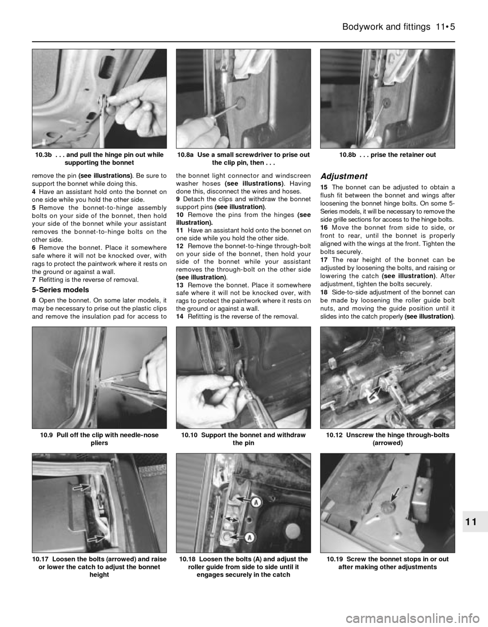
remove the pin (see illustrations). Be sure to
support the bonnet while doing this.
4Have an assistant hold onto the bonnet on
one side while you hold the other side.
5Remove the bonnet-to-hinge assembly
bolts on your side of the bonnet, then hold
your side of the bonnet while your assistant
removes the bonnet-to-hinge bolts on the
other side.
6Remove the bonnet. Place it somewhere
safe where it will not be knocked over, with
rags to protect the paintwork where it rests on
the ground or against a wall.
7Refitting is the reverse of removal.
5-Series models
8Open the bonnet. On some later models, it
may be necessary to prise out the plastic clips
and remove the insulation pad for access tothe bonnet light connector and windscreen
washer hoses (see illustrations). Having
done this, disconnect the wires and hoses.
9Detach the clips and withdraw the bonnet
support pins (see illustration).
10Remove the pins from the hinges (see
illustration).
11Have an assistant hold onto the bonnet on
one side while you hold the other side.
12Remove the bonnet-to-hinge through-bolt
on your side of the bonnet, then hold your
side of the bonnet while your assistant
removes the through-bolt on the other side
(see illustration).
13Remove the bonnet. Place it somewhere
safe where it will not be knocked over, with
rags to protect the paintwork where it rests on
the ground or against a wall.
14Refitting is the reverse of the removal.
Adjustment
15The bonnet can be adjusted to obtain a
flush fit between the bonnet and wings after
loosening the bonnet hinge bolts. On some 5-
Series models, it will be necessary to remove the
side grille sections for access to the hinge bolts.
16Move the bonnet from side to side, or
front to rear, until the bonnet is properly
aligned with the wings at the front. Tighten the
bolts securely.
17The rear height of the bonnet can be
adjusted by loosening the bolts, and raising or
lowering the catch (see illustration). After
adjustment, tighten the bolts securely.
18Side-to-side adjustment of the bonnet can
be made by loosening the roller guide bolt
nuts, and moving the guide position until it
slides into the catch properly (see illustration).
Bodywork and fittings 11•5
10.8b . . . prise the retainer out10.8a Use a small screwdriver to prise out
the clip pin, then . . .10.3b . . . and pull the hinge pin out while
supporting the bonnet
10.19 Screw the bonnet stops in or out
after making other adjustments10.18 Loosen the bolts (A) and adjust the
roller guide from side to side until it
engages securely in the catch10.17 Loosen the bolts (arrowed) and raise
or lower the catch to adjust the bonnet
height
10.12 Unscrew the hinge through-bolts
(arrowed)10.10 Support the bonnet and withdraw
the pin10.9 Pull off the clip with needle-nose
pliers
11
Page 166 of 228
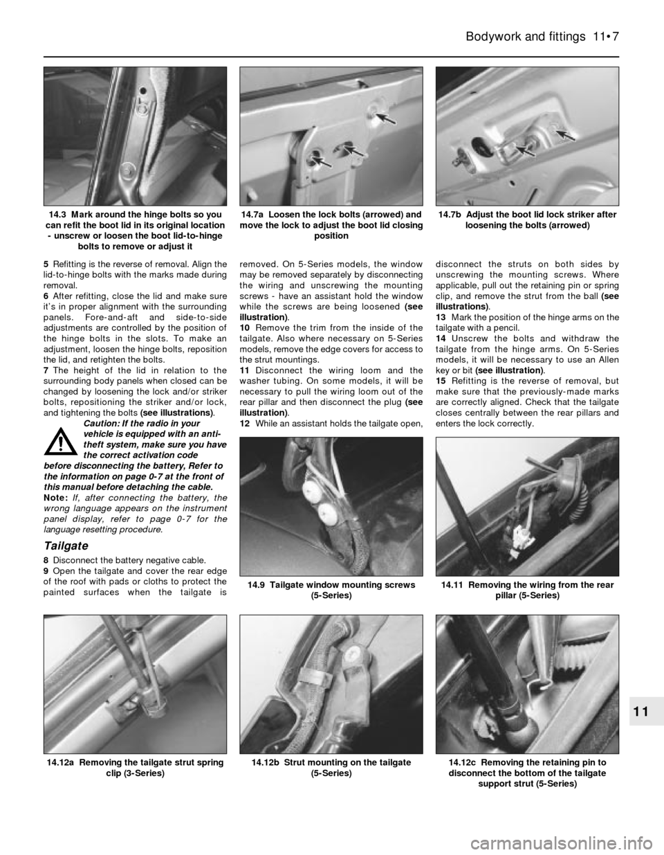
5Refitting is the reverse of removal. Align the
lid-to-hinge bolts with the marks made during
removal.
6After refitting, close the lid and make sure
it’s in proper alignment with the surrounding
panels. Fore-and-aft and side-to-side
adjustments are controlled by the position of
the hinge bolts in the slots. To make an
adjustment, loosen the hinge bolts, reposition
the lid, and retighten the bolts.
7The height of the lid in relation to the
surrounding body panels when closed can be
changed by loosening the lock and/or striker
bolts, repositioning the striker and/or lock,
and tightening the bolts (see illustrations).
Caution: If the radio in your
vehicle is equipped with an anti-
theft system, make sure you have
the correct activation code
before disconnecting the battery, Refer to
the information on page 0-7 at the front of
this manual before detaching the cable.
Note: If, after connecting the battery, the
wrong language appears on the instrument
panel display, refer to page 0-7 for the
language resetting procedure.
Tailgate
8Disconnect the battery negative cable.
9Open the tailgate and cover the rear edge
of the roof with pads or cloths to protect the
painted surfaces when the tailgate isremoved. On 5-Series models, the window
may be removed separately by disconnecting
the wiring and unscrewing the mounting
screws - have an assistant hold the window
while the screws are being loosened (see
illustration).
10Remove the trim from the inside of the
tailgate. Also where necessary on 5-Series
models, remove the edge covers for access to
the strut mountings.
11Disconnect the wiring loom and the
washer tubing. On some models, it will be
necessary to pull the wiring loom out of the
rear pillar and then disconnect the plug (see
illustration).
12While an assistant holds the tailgate open,disconnect the struts on both sides by
unscrewing the mounting screws. Where
applicable, pull out the retaining pin or spring
clip, and remove the strut from the ball (see
illustrations).
13Mark the position of the hinge arms on the
tailgate with a pencil.
14Unscrew the bolts and withdraw the
tailgate from the hinge arms. On 5-Series
models, it will be necessary to use an Allen
key or bit (see illustration).
15Refitting is the reverse of removal, but
make sure that the previously-made marks
are correctly aligned. Check that the tailgate
closes centrally between the rear pillars and
enters the lock correctly.
Bodywork and fittings 11•7
14.7b Adjust the boot lid lock striker after
loosening the bolts (arrowed)14.7a Loosen the lock bolts (arrowed) and
move the lock to adjust the boot lid closing
position14.3 Mark around the hinge bolts so you
can refit the boot lid in its original location
- unscrew or loosen the boot lid-to-hinge
bolts to remove or adjust it
14.12c Removing the retaining pin to
disconnect the bottom of the tailgate
support strut (5-Series)14.12b Strut mounting on the tailgate
(5-Series)14.12a Removing the tailgate strut spring
clip (3-Series)
14.11 Removing the wiring from the rear
pillar (5-Series)14.9 Tailgate window mounting screws
(5-Series)
11
Page 170 of 228
Finding a short-circuit
One method of finding a short-circuit is to
remove the fuse and connect a test light or
voltmeter in its place. There should be no
voltage present in the circuit. Move the
electrical connectors from side-to-side while
watching the test light. If the bulb goes on,
there is a short to earth somewhere in that
area, probably where the insulation has been
rubbed through. The same test can be
performed on each component in a circuit,
even a switch.
Earth check
Perform a earth check to see whether a
component is properly earthed (passing
current back via the vehicle body). Disconnect
the battery, and connect one lead of a self-
powered test light (often known as a
continuity tester) to a known good earth.
Connect the other lead to the wire or earth
connection being tested. The bulb should
light, indicating a good earth connection. If
not, dismantle the connection, and clean all
relevant parts thoroughly. When re-making
the connection, use serrated (shakeproof)
washers if possible, and tighten all bolts, etc,
securely.
Caution: If the radio in your
vehicle is equipped with an anti-
theft system, make sure you have
the correct activation code
before disconnecting the battery, Refer to
the information on page 0-7 at the front of
this manual before detaching the cable.
Note: If, after connecting the battery, the
wrong language appears on the instrument
panel display, refer to page 0-7 for the
language resetting procedure.
Continuity check
A continuity check determines if there are
any breaks in a circuit - if it is conducting
electricity properly. With the circuit off (no
power in the circuit), a self-powered continuity
tester can be used to check the circuit.
Connect the test leads to both ends of the
circuit, and if the test light comes on, the
circuit is passing current properly. If the light
doesn’t come on, there is a break somewhere
in the circuit. The same procedure can be
used to test a switch, by connecting the
continuity tester to the power-in and power-
out sides of the switch. With the switch turned
on, the test light should come on.
Finding an open-circuit
When diagnosing for possible open-
circuits, it is often difficult to locate them by
sight, because oxidation or terminal
misalignment are hidden by the connectors.
Intermittent problems are often caused by
oxidised or loose connections. Merely
wiggling an electrical connector may correct
the open-circuit condition, albeit temporarily.
Dismantle the connector, and spray with a
water-dispersant aerosol. On simpler
connectors, it may be possible to carefullybend the connector pins inside, to improve
the metal-to-metal contact - don’t damage
the connector in the process, however.
3 Fuses- general information
1
The electrical circuits of the vehicle are
protected by a combination of fuses and
circuit breakers. The fusebox is located in the
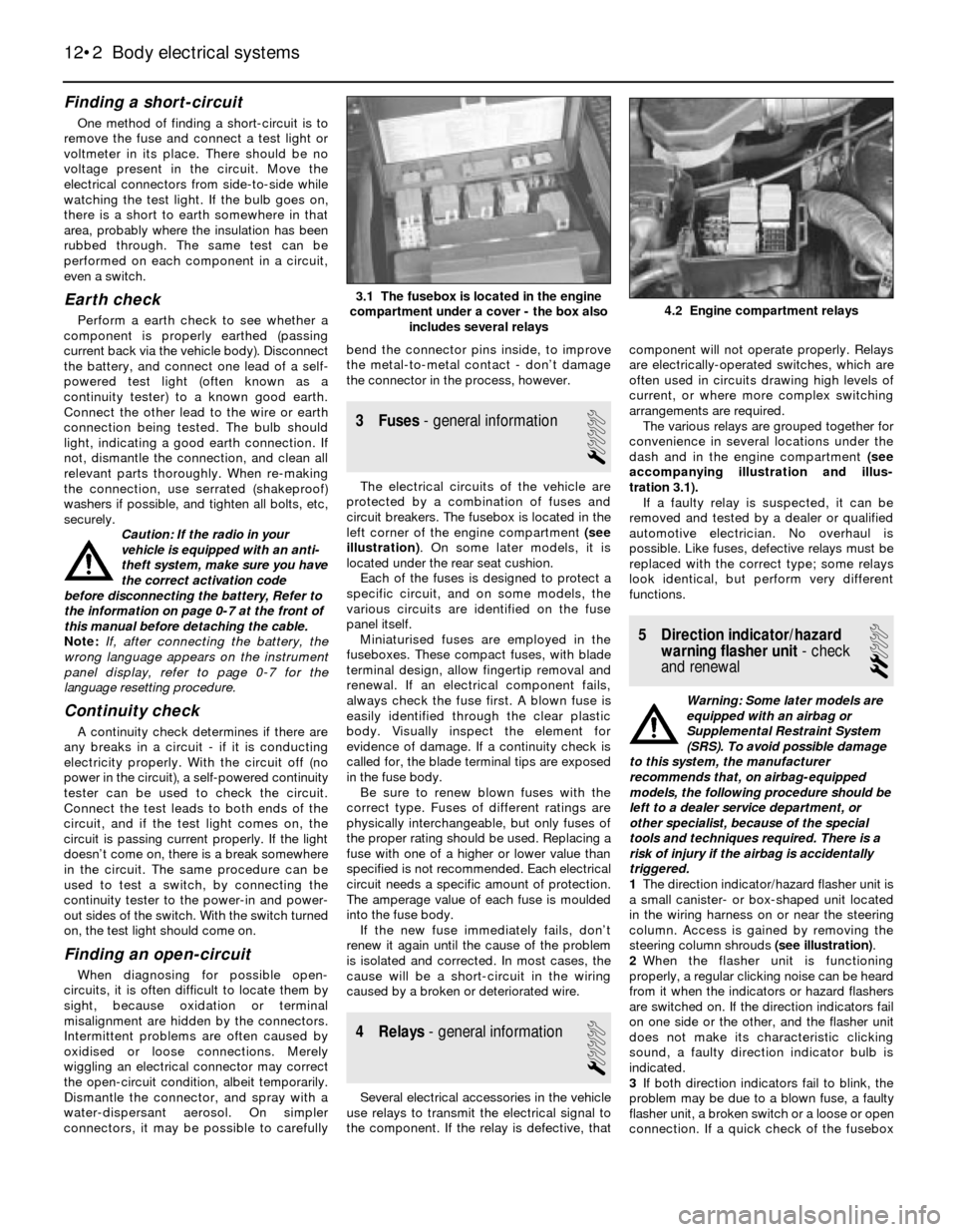
left corner of the engine compartment (see
illustration). On some later models, it is
located under the rear seat cushion.
Each of the fuses is designed to protect a
specific circuit, and on some models, the
various circuits are identified on the fuse
panel itself.
Miniaturised fuses are employed in the
fuseboxes. These compact fuses, with blade
terminal design, allow fingertip removal and
renewal. If an electrical component fails,
always check the fuse first. A blown fuse is
easily identified through the clear plastic
body. Visually inspect the element for
evidence of damage. If a continuity check is
called for, the blade terminal tips are exposed
in the fuse body.
Be sure to renew blown fuses with the
correct type. Fuses of different ratings are
physically interchangeable, but only fuses of
the proper rating should be used. Replacing a
fuse with one of a higher or lower value than
specified is not recommended. Each electrical
circuit needs a specific amount of protection.
The amperage value of each fuse is moulded
into the fuse body.
If the new fuse immediately fails, don’t
renew it again until the cause of the problem
is isolated and corrected. In most cases, the
cause will be a short-circuit in the wiring
caused by a broken or deteriorated wire.
4 Relays- general information
1
Several electrical accessories in the vehicle
use relays to transmit the electrical signal to
the component. If the relay is defective, thatcomponent will not operate properly. Relays
are electrically-operated switches, which are
often used in circuits drawing high levels of
current, or where more complex switching
arrangements are required.
The various relays are grouped together for
convenience in several locations under the
dash and in the engine compartment (see
accompanying illustration and illus-
tration 3.1).
If a faulty relay is suspected, it can be
removed and tested by a dealer or qualified
automotive electrician. No overhaul is
possible. Like fuses, defective relays must be
replaced with the correct type; some relays
look identical, but perform very different
functions.
5 Direction indicator/hazard
warning flasher unit- check
and renewal
2
Warning: Some later models are
equipped with an airbag or
Supplemental Restraint System
(SRS). To avoid possible damage
to this system, the manufacturer
recommends that, on airbag-equipped
models, the following procedure should be
left to a dealer service department, or
other specialist, because of the special
tools and techniques required. There is a
risk of injury if the airbag is accidentally
triggered.
1The direction indicator/hazard flasher unit is
a small canister- or box-shaped unit located
in the wiring harness on or near the steering
column. Access is gained by removing the
steering column shrouds (see illustration).
2When the flasher unit is functioning
properly, a regular clicking noise can be heard
from it when the indicators or hazard flashers
are switched on. If the direction indicators fail
on one side or the other, and the flasher unit
does not make its characteristic clicking
sound, a faulty direction indicator bulb is
indicated.
3If both direction indicators fail to blink, the
problem may be due to a blown fuse, a faulty
flasher unit, a broken switch or a loose or open
connection. If a quick check of the fusebox
12•2 Body electrical systems
4.2 Engine compartment relays3.1 The fusebox is located in the engine
compartment under a cover - the box also
includes several relays
Page 171 of 228
indicates that the direction indicator and/or
hazard fuse has blown, check the wiring for a
short-circuit before fitting a new fuse.
4Make sure that the new unit is identical to
the original. Compare the old one to the new
one before fitting it.
5Refitting is the reverse of removal.
6 Steering column switches-
removal and refitting
1
Warning: Some later models are
equipped with an airbag or
Supplemental Restraint System
(SRS). To avoid possible damage
to this system, the manufacturer
recommends that, on airbag-equipped
models, the following procedure should be
left to a dealer service department, or
other specialist, because of the special
tools and techniques required. There is a
risk of injury if the airbag is accidentally
triggered.
Caution: If the radio in your
vehicle is equipped with an anti-
theft system, make sure you have
the correct activation code
before disconnecting the battery, Refer to
the information on page 0-7 at the front of
this manual before detaching the cable.
Note: If, after connecting the battery, the
wrong language appears on the instrument
panel display, refer to page 0-7 for the
language resetting procedure.
1Disconnect the battery negative cable,
remove the steering wheel (see Chapter 10)
and steering column shrouds (see Chapter 11).
Direction indicator/headlight
switch
2Where necessary, remove the switch
mounting screws. Depress the tabs and pull
the switch out of the steering column
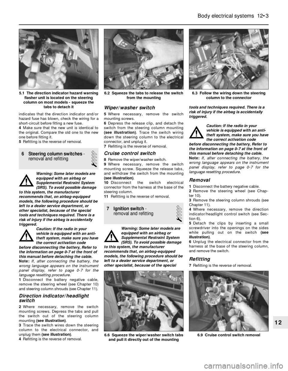
mounting (see illustration).
3Trace the switch wires down the steering
column to the electrical connector, and
unplug them (see illustration).
4Refitting is the reverse of removal.
Wiper/washer switch
5Where necessary, remove the switch
mounting screws.
6Depress the release clip, and detach the
switch from the steering column mounting
(see illustration). Trace the switch wiring
down the steering column to the electrical
connector, and unplug it.
7Refitting is the reverse of removal.
Cruise control switch
8Remove the wiper/washer switch.
9Where necessary, remove the switch
mounting screw. Squeeze the release tabs,
and withdraw the switch from the mounting
(see illustration).
10Disconnect the switch electrical
connector from the harness at the base of the
steering column.
11Refitting is the reverse of removal.
7 Ignition switch-
removal and refitting
1
Warning: Some later models are
equipped with an airbag or
Supplemental Restraint System
(SRS). To avoid possible damage
to this system, the manufacturer
recommends that, on airbag-equipped
models, the following procedure should be
left to a dealer service department, or
other specialist, because of the specialtools and techniques required. There is a
risk of injury if the airbag is accidentally
triggered.
Caution: If the radio in your
vehicle is equipped with an anti-
theft system, make sure you have
the correct activation code
before disconnecting the battery, Refer to
the information on page 0-7 at the front of
this manual before detaching the cable.
Note: If, after connecting the battery, the
wrong language appears on the instrument
panel display, refer to page 0-7 for the
language resetting procedure.
Removal
1Disconnect the battery negative cable.
2Remove the steering wheel (see Chap-
ter 10).
3Remove the steering column shrouds (see
Chapter 11).
4Where necessary, remove the direction
indicator/headlight control switch (see Sec-
tion 6).
5Detach the clips by inserting a small
screwdriver into the openings on the sides
while pulling out on the switch (see
illustration).
6Unplug the electrical connector from the
harness at the base of the steering column,
and remove the switch.
Refitting
7Refitting is the reverse of removal.
Body electrical systems 12•3
6.3 Follow the wiring down the steering
column to the connector6.2 Squeeze the tabs to release the switch
from the mounting
6.9 Cruise control switch removal6.6 Squeeze the wiper/washer switch tabs
and pull it directly out of the mounting
12
5.1 The direction indicator/hazard warning
flasher unit is located on the steering
column on most models - squeeze the
tabs to detach it
Page 175 of 228
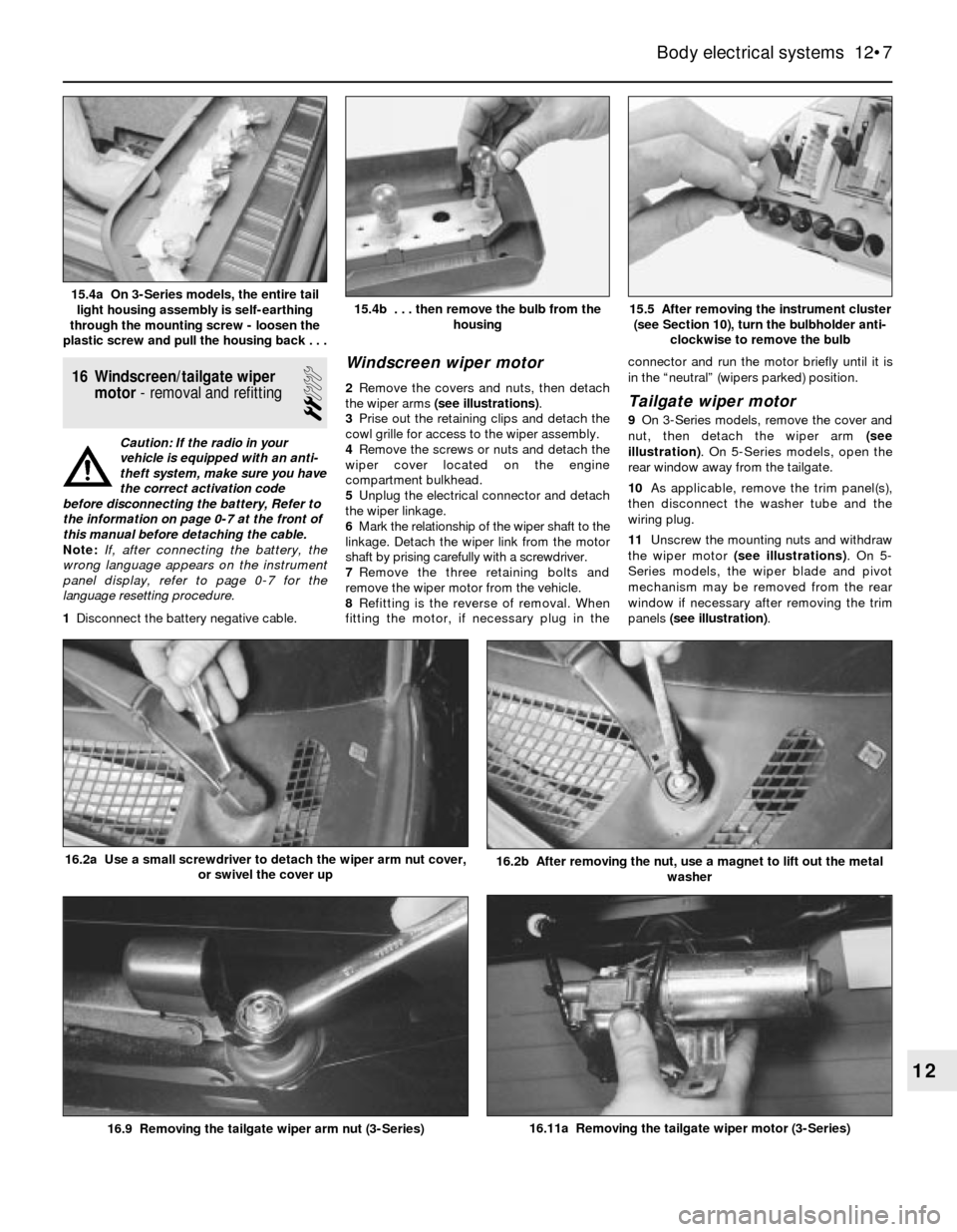
16 Windscreen/tailgate wiper
motor- removal and refitting
2
Caution: If the radio in your
vehicle is equipped with an anti-
theft system, make sure you have
the correct activation code
before disconnecting the battery, Refer to
the information on page 0-7 at the front of
this manual before detaching the cable.
Note: If, after connecting the battery, the
wrong language appears on the instrument
panel display, refer to page 0-7 for the
language resetting procedure.
1Disconnect the battery negative cable.
Windscreen wiper motor
2Remove the covers and nuts, then detach
the wiper arms (see illustrations).
3Prise out the retaining clips and detach the
cowl grille for access to the wiper assembly.
4Remove the screws or nuts and detach the
wiper cover located on the engine
compartment bulkhead.
5Unplug the electrical connector and detach
the wiper linkage.
6Mark the relationship of the wiper shaft to the
linkage. Detach the wiper link from the motor
shaft by prising carefully with a screwdriver.
7Remove the three retaining bolts and
remove the wiper motor from the vehicle.
8Refitting is the reverse of removal. When
fitting the motor, if necessary plug in theconnector and run the motor briefly until it is
in the “neutral” (wipers parked) position.Tailgate wiper motor
9On 3-Series models, remove the cover and
nut, then detach the wiper arm (see
illustration). On 5-Series models, open the
rear window away from the tailgate.
10As applicable, remove the trim panel(s),
then disconnect the washer tube and the
wiring plug.
11Unscrew the mounting nuts and withdraw
the wiper motor (see illustrations). On 5-
Series models, the wiper blade and pivot
mechanism may be removed from the rear
window if necessary after removing the trim
panels (see illustration).
Body electrical systems 12•7
15.5 After removing the instrument cluster
(see Section 10), turn the bulbholder anti-
clockwise to remove the bulb15.4b . . . then remove the bulb from the
housing15.4a On 3-Series models, the entire tail
light housing assembly is self-earthing
through the mounting screw - loosen the
plastic screw and pull the housing back . . .
16.11a Removing the tailgate wiper motor (3-Series)
16.2b After removing the nut, use a magnet to lift out the metal
washer16.2a Use a small screwdriver to detach the wiper arm nut cover,
or swivel the cover up
16.9 Removing the tailgate wiper arm nut (3-Series)
12
Page 189 of 228

Wiring diagrams 12•21
12
Typical headlight washer system wiring diagram
Page 190 of 228

12•22 Wiring diagrams
Key to electric window system wiring diagram
Key to headlight washer system wiring diagram
Page 203 of 228
REF•2MOT Test Checks
Seat belts and seats
Note: The following checks are applicable to
all seat belts, front and rear.
MExamine the webbing of all the belts
(including rear belts if fitted) for cuts, serious
fraying or deterioration. Fasten and unfasten
each belt to check the buckles. If applicable,
check the retracting mechanism. Check the
security of all seat belt mountings accessible
from inside the vehicle.
MThe front seats themselves must be
securely attached and the backrests must
lock in the upright position.
Doors
MBoth front doors must be able to be opened
and closed from outside and inside, and must
latch securely when closed.
Vehicle identification
MNumber plates must be in good condition,
secure and legible, with letters and numbers
correctly spaced – spacing at (A) should be
twice that at (B).
MThe VIN plate and/or homologation plate
must be legible.
Electrical equipment
MSwitch on the ignition and check the
operation of the horn.
MCheck the windscreen washers and wipers,
examining the wiper blades; renew damaged
or perished blades. Also check the operation
of the stop-lights.
MCheck the operation of the sidelights and
number plate lights. The lenses and reflectors
must be secure, clean and undamaged.
MCheck the operation and alignment of the
headlights. The headlight reflectors must not
be tarnished and the lenses must be
undamaged.
MSwitch on the ignition and check the
operation of the direction indicators (including
the instrument panel tell-tale) and the hazard
warning lights. Operation of the sidelights and
stop-lights must not affect the indicators - if it
does, the cause is usually a bad earth at the
rear light cluster.
MCheck the operation of the rear foglight(s),
including the warning light on the instrument
panel or in the switch.
Footbrake
MExamine the master cylinder, brake pipes
and servo unit for leaks, loose mountings,
corrosion or other damage.
MThe fluid reservoir must be secure and the
fluid level must be between the upper (A) and
lower (B) markings.MInspect both front brake flexible hoses for
cracks or deterioration of the rubber. Turn the
steering from lock to lock, and ensure that the
hoses do not contact the wheel, tyre, or any
part of the steering or suspension mechanism.
With the brake pedal firmly depressed, check
the hoses for bulges or leaks under pressure.
Steering and suspension
MHave your assistant turn the steering wheel
from side to side slightly, up to the point where
the steering gear just begins to transmit this
movement to the roadwheels. Check for
excessive free play between the steering
wheel and the steering gear, indicating wear or
insecurity of the steering column joints, the
column-to-steering gear coupling, or the
steering gear itself.
MHave your assistant turn the steering wheel
more vigorously in each direction, so that the
roadwheels just begin to turn. As this is done,
examine all the steering joints, linkages,
fittings and attachments. Renew any
component that shows signs of wear or
damage. On vehicles with power steering,
check the security and condition of the
steering pump, drivebelt and hoses.
MCheck that the vehicle is standing level,
and at approximately the correct ride height.
Shock absorbers
MDepress each corner of the vehicle in turn,
then release it. The vehicle should rise and
then settle in its normal position. If the vehicle
continues to rise and fall, the shock absorber
is defective. A shock absorber which has
seized will also cause the vehicle to fail.
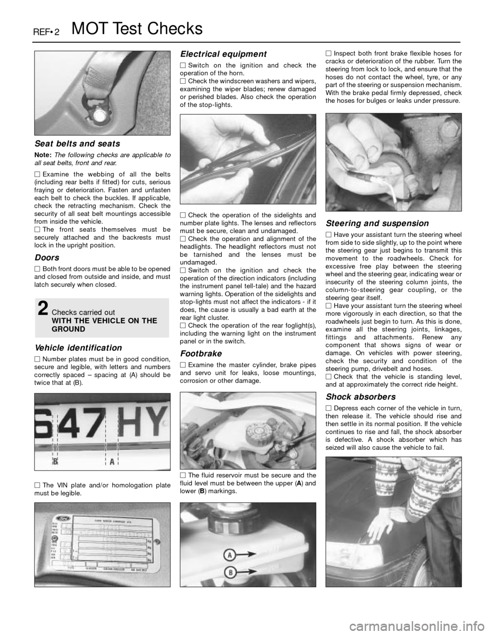
2Checks carried out
WITH THE VEHICLE ON THE
GROUND
Page 209 of 228

REF•8General Repair Procedures
Whenever servicing, repair or overhaul work
is carried out on the car or its components,
observe the following procedures and
instructions. This will assist in carrying out the
operation efficiently and to a professional
standard of workmanship.
Joint mating faces and gaskets
When separating components at their
mating faces, never insert screwdrivers or
similar implements into the joint between the
faces in order to prise them apart. This can
cause severe damage which results in oil
leaks, coolant leaks, etc upon reassembly.
Separation is usually achieved by tapping
along the joint with a soft-faced hammer in
order to break the seal. However, note that
this method may not be suitable where
dowels are used for component location.
Where a gasket is used between the mating
faces of two components, a new one must be
fitted on reassembly; fit it dry unless otherwise
stated in the repair procedure. Make sure that
the mating faces are clean and dry, with all
traces of old gasket removed. When cleaning a
joint face, use a tool which is unlikely to score
or damage the face, and remove any burrs or
nicks with an oilstone or fine file.
Make sure that tapped holes are cleaned
with a pipe cleaner, and keep them free of
jointing compound, if this is being used,
unless specifically instructed otherwise.
Ensure that all orifices, channels or pipes
are clear, and blow through them, preferably
using compressed air.
Oil seals
Oil seals can be removed by levering them
out with a wide flat-bladed screwdriver or
similar implement. Alternatively, a number of
self-tapping screws may be screwed into the
seal, and these used as a purchase for pliers or
some similar device in order to pull the seal free.
Whenever an oil seal is removed from its
working location, either individually or as part
of an assembly, it should be renewed.
The very fine sealing lip of the seal is easily
damaged, and will not seal if the surface it
contacts is not completely clean and free from
scratches, nicks or grooves. If the original
sealing surface of the component cannot be
restored, and the manufacturer has not made
provision for slight relocation of the seal
relative to the sealing surface, the component
should be renewed.
Protect the lips of the seal from any surface
which may damage them in the course of
fitting. Use tape or a conical sleeve where
possible. Lubricate the seal lips with oil before
fitting and, on dual-lipped seals, fill the space
between the lips with grease.
Unless otherwise stated, oil seals must be
fitted with their sealing lips toward the
lubricant to be sealed.
Use a tubular drift or block of wood of the
appropriate size to install the seal and, if the
seal housing is shouldered, drive the seal
down to the shoulder. If the seal housing isunshouldered, the seal should be fitted with
its face flush with the housing top face (unless
otherwise instructed).
Screw threads and fastenings
Seized nuts, bolts and screws are quite a
common occurrence where corrosion has set
in, and the use of penetrating oil or releasing
fluid will often overcome this problem if the
offending item is soaked for a while before
attempting to release it. The use of an impact
driver may also provide a means of releasing
such stubborn fastening devices, when used
in conjunction with the appropriate
screwdriver bit or socket. If none of these
methods works, it may be necessary to resort
to the careful application of heat, or the use of
a hacksaw or nut splitter device.
Studs are usually removed by locking two
nuts together on the threaded part, and then
using a spanner on the lower nut to unscrew
the stud. Studs or bolts which have broken off
below the surface of the component in which
they are mounted can sometimes be removed
using a stud extractor. Always ensure that a
blind tapped hole is completely free from oil,
grease, water or other fluid before installing
the bolt or stud. Failure to do this could cause
the housing to crack due to the hydraulic
action of the bolt or stud as it is screwed in.
When tightening a castellated nut to accept
a split pin, tighten the nut to the specified
torque, where applicable, and then tighten
further to the next split pin hole. Never slacken
the nut to align the split pin hole, unless stated
in the repair procedure.
When checking or retightening a nut or bolt
to a specified torque setting, slacken the nut
or bolt by a quarter of a turn, and then
retighten to the specified setting. However,
this should not be attempted where angular
tightening has been used.
For some screw fastenings, notably
cylinder head bolts or nuts, torque wrench
settings are no longer specified for the latter
stages of tightening, “angle-tightening” being
called up instead. Typically, a fairly low torque
wrench setting will be applied to the
bolts/nuts in the correct sequence, followed
by one or more stages of tightening through
specified angles.
Locknuts, locktabs and washers
Any fastening which will rotate against a
component or housing during tightening
should always have a washer between it and
the relevant component or housing.
Spring or split washers should always be
renewed when they are used to lock a critical
component such as a big-end bearing
retaining bolt or nut. Locktabs which are
folded over to retain a nut or bolt should
always be renewed.
Self-locking nuts can be re-used in non-
critical areas, providing resistance can be felt
when the locking portion passes over the bolt
or stud thread. However, it should be noted
that self-locking stiffnuts tend to lose theireffectiveness after long periods of use, and
should then be renewed as a matter of course.
Split pins must always be replaced with
new ones of the correct size for the hole.
When thread-locking compound is found
on the threads of a fastener which is to be re-
used, it should be cleaned off with a wire
brush and solvent, and fresh compound
applied on reassembly.
Special tools
Some repair procedures in this manual
entail the use of special tools such as a press,
two or three-legged pullers, spring com-
pressors, etc. Wherever possible, suitable
readily-available alternatives to the manu-
facturer’s special tools are described, and are
shown in use. In some instances, where no
alternative is possible, it has been necessary
to resort to the use of a manufacturer’s tool,
and this has been done for reasons of safety
as well as the efficient completion of the repair
operation. Unless you are highly-skilled and
have a thorough understanding of the
procedures described, never attempt to
bypass the use of any special tool when the
procedure described specifies its use. Not
only is there a very great risk of personal
injury, but expensive damage could be
caused to the components involved.
Environmental considerations
When disposing of used engine oil, brake
fluid, antifreeze, etc, give due consideration to
any detrimental environmental effects. Do not,
for instance, pour any of the above liquids
down drains into the general sewage system,
or onto the ground to soak away. Many local
council refuse tips provide a facility for waste
oil disposal, as do some garages. If none of
these facilities are available, consult your local
Environmental Health Department, or the
National Rivers Authority, for further advice.
With the universal tightening-up of legis-
lation regarding the emission of environmen-
tally-harmful substances from motor vehicles,
most vehicles have tamperproof devices fitted
to the main adjustment points of the fuel
system. These devices are primarily designed
to prevent unqualified persons from adjusting
the fuel/air mixture, with the chance of a
consequent increase in toxic emissions. If
such devices are found during servicing or
overhaul, they should, wherever possible, be
renewed or refitted in accordance with the
manufacturer’s requirements or current
legislation.
Note: It is
antisocial and
illegal to dump
oil down the
drain. To find
the location of
your local oil
recycling
bank, call this
number free.
Page 223 of 228
REF•23
REF
Glossary of Technical Terms
JJump startStarting the engine of a vehicle
with a discharged or weak battery by
attaching jump leads from the weak battery to
a charged or helper battery.
LLoad Sensing Proportioning Valve (LSPV)A
brake hydraulic system control valve that
works like a proportioning valve, but also
takes into consideration the amount of weight
carried by the rear axle.
LocknutA nut used to lock an adjustment
nut, or other threaded component, in place.
For example, a locknut is employed to keep
the adjusting nut on the rocker arm in
position.
LockwasherA form of washer designed to
prevent an attaching nut from working loose.
MMacPherson strutA type of front
suspension system devised by Earle
MacPherson at Ford of England. In its original
form, a simple lateral link with the anti-roll bar
creates the lower control arm. A long strut - an
integral coil spring and shock absorber - is
mounted between the body and the steering
knuckle. Many modern so-called MacPherson
strut systems use a conventional lower A-arm
and don’t rely on the anti-roll bar for location.
MultimeterAn electrical test instrument with
the capability to measure voltage, current and
resistance.
NNOxOxides of Nitrogen. A common toxic
pollutant emitted by petrol and diesel engines
at higher temperatures.
OOhmThe unit of electrical resistance. One
volt applied to a resistance of one ohm will
produce a current of one amp.
OhmmeterAn instrument for measuring
electrical resistance.
O-ringA type of sealing ring made of a
special rubber-like material; in use, the O-ring
is compressed into a groove to provide the
sealing action.Overhead cam (ohc) engineAn engine with
the camshaft(s) located on top of the cylinder
head(s).
Overhead valve (ohv) engineAn engine with
the valves located in the cylinder head, but
with the camshaft located in the engine block.
Oxygen sensorA device installed in the
engine exhaust manifold, which senses the
oxygen content in the exhaust and converts
this information into an electric current. Also
called a Lambda sensor.
PPhillips screwA type of screw head having a
cross instead of a slot for a corresponding
type of screwdriver.
PlastigageA thin strip of plastic thread,
available in different sizes, used for measuring
clearances. For example, a strip of Plastigage
is laid across a bearing journal. The parts are
assembled and dismantled; the width of the
crushed strip indicates the clearance between
journal and bearing.
Propeller shaftThe long hollow tube with
universal joints at both ends that carries
power from the transmission to the differential
on front-engined rear wheel drive vehicles.
Proportioning valveA hydraulic control
valve which limits the amount of pressure to
the rear brakes during panic stops to prevent
wheel lock-up.
RRack-and-pinion steeringA steering system
with a pinion gear on the end of the steering
shaft that mates with a rack (think of a geared
wheel opened up and laid flat). When the
steering wheel is turned, the pinion turns,
moving the rack to the left or right. This
movement is transmitted through the track
rods to the steering arms at the wheels.
RadiatorA liquid-to-air heat transfer device
designed to reduce the temperature of the
coolant in an internal combustion engine
cooling system.
RefrigerantAny substance used as a heat
transfer agent in an air-conditioning system.
R-12 has been the principle refrigerant for
many years; recently, however, manufacturers
have begun using R-134a, a non-CFC
substance that is considered less harmful tothe ozone in the upper atmosphere.
Rocker armA lever arm that rocks on a shaft
or pivots on a stud. In an overhead valve
engine, the rocker arm converts the upward
movement of the pushrod into a downward
movement to open a valve.
RotorIn a distributor, the rotating device
inside the cap that connects the centre
electrode and the outer terminals as it turns,
distributing the high voltage from the coil
secondary winding to the proper spark plug.
Also, that part of an alternator which rotates
inside the stator. Also, the rotating assembly
of a turbocharger, including the compressor
wheel, shaft and turbine wheel.
RunoutThe amount of wobble (in-and-out
movement) of a gear or wheel as it’s rotated.
The amount a shaft rotates “out-of-true.” The
out-of-round condition of a rotating part.
SSealantA liquid or paste used to prevent
leakage at a joint. Sometimes used in
conjunction with a gasket.
Sealed beam lampAn older headlight design
which integrates the reflector, lens and
filaments into a hermetically-sealed one-piece
unit. When a filament burns out or the lens
cracks, the entire unit is simply replaced.
Serpentine drivebeltA single, long, wide
accessory drivebelt that’s used on some
newer vehicles to drive all the accessories,
instead of a series of smaller, shorter belts.
Serpentine drivebelts are usually tensioned by
an automatic tensioner.
ShimThin spacer, commonly used to adjust
the clearance or relative positions between
two parts. For example, shims inserted into or
under bucket tappets control valve
clearances. Clearance is adjusted by
changing the thickness of the shim.
Slide hammerA special puller that screws
into or hooks onto a component such as a
shaft or bearing; a heavy sliding handle on the
shaft bottoms against the end of the shaft to
knock the component free.
SprocketA tooth or projection on the
periphery of a wheel, shaped to engage with a
chain or drivebelt. Commonly used to refer to
the sprocket wheel itself.
Starter inhibitor switchOn vehicles with an
O-ring
Serpentine drivebelt
Plastigage