stop BMW 3 SERIES 1991 E30 Workshop Manual
[x] Cancel search | Manufacturer: BMW, Model Year: 1991, Model line: 3 SERIES, Model: BMW 3 SERIES 1991 E30Pages: 228, PDF Size: 7.04 MB
Page 7 of 228

0•7Anti-theft audio system
Anti-theft audio system
General information
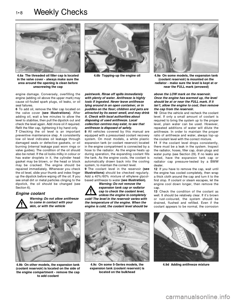
Some models are equipped with an audio
system having an anti-theft feature that will
render the stereo inoperative if stolen. If the
power source to the stereo is cut, the stereo
won’t work even if the power source is
immediately re-connected. If your vehicle is
equipped with this anti-theft system, do not
disconnect the battery or remove the stereo
unless you have the individual code number
for the stereo.
Refer to the owner’s handbook suppliedwith the vehicle for more complete
information on this audio system and its anti-
theft feature.
Unlocking procedure
1Turn on the radio. The word “CODE” should
appear on the display.
2Using the station preset selector buttons,
enter the five-digit code. If you make a
mistake when entering the code, continue
the five-digit sequence anyway. If you hear
a “beep,” however, stop immediately andstart the sequence over again. Note: Yo u
have three attempts to enter the correct
code. If the correct code isn’t entered in
three tries, you’ll have to wait one hour, with
the radio on, before you enter the codes
again.
5Once the code has been entered correctly,
the word “CODE” should disappear from the
display, and the radio should play (you’ll have
to tune-in and enter your preset stations,
however).
6If you have lost your code number, contact
a BMW dealer service department.
Instrument panel language display
On some later models, disconnecting the
battery may cause the instrument panel
display to default to the German language
(this does not usually apply to UK models). If
it is necessary to reset the correct language
after the battery is reconnected, proceed as
follows. With all the doors shut and theignition on (engine not running), press the trip
reset button until the panel displays the
desired language. There are eight languages
available. If you wish to bypass a particular
selection, release the reset button and press
again - this will cause the display to advance
to the next language. Once the correctlanguage has been selected, continue holding
the reset button until the display reads “I.O.
Version 2.0”. Continue holding the button until
it reads “H.P. Version 3.4”, then release the
button.
Page 18 of 228
engine damage. Conversely, overfilling the
engine (adding oil above the upper mark) may
cause oil-fouled spark plugs, oil leaks, or oil
seal failures.
6To add oil, remove the filler cap located on
the valve cover (see illustrations). After
adding oil, wait a few minutes to allow the
level to stabilise, then pull the dipstick out and
check the level again. Add more oil if required.
Refit the filler cap, tightening it by hand only.
7Checking the oil level is an important
preventive maintenance step. A consistently
low oil level indicates oil leakage through
damaged seals or defective gaskets, or oil
burning (internal leakage past worn rings or
valve guides). The condition of the oil should
also be noted. If the oil looks milky in colour or
has water droplets in it, the cylinder head
gasket may be blown, or the head or block
may be cracked. The engine should be
repaired immediately. Whenever you check
the oil level, slide your thumb and index finger
up the dipstick before wiping off the oil. If you
see small dirt or metal particles clinging to the
dipstick, the oil should be changed (see
Section 6).
Engine coolant
Warning: Do not allow antifreeze
to come in contact with your
skin, or with the vehiclepaintwork. Rinse off spills immediately
with plenty of water. Antifreeze is highly
toxic if ingested. Never leave antifreeze
lying around in an open container, or in
puddles on the floor; children and pets are
attracted by its sweet smell, and may drink
it. Check with local authorities about
disposing of used antifreeze. Local
collection centres may exist, to see that
antifreeze is disposed of safely.
8All vehicles covered by this manual are
equipped with a pressurised coolant recovery
system. On most models, a white plastic
expansion tank (or coolant reservoir) located
in the engine compartment is connected by a
hose to the radiator. As the engine heats up
during operation, the expanding coolant fills
the tank. As the engine cools, the coolant is
automatically drawn back into the cooling
system, to maintain the correct level.
9The coolant level in the reservoir (see
illustrations)should be checked regularly.
Add a 40%/60% mixture of ethylene glycol-
based antifreeze to water (see illustration).
Warning: Do not remove the
expansion tank cap or radiator
cap to check the coolant level,
unless the engine is completely
cold! The level in the reservoir varies with
the temperature of the engine. When the
engine is cold, the coolant level should beabove the LOW mark on the reservoir.
Once the engine has warmed up, the level
should be at or near the FULL mark. If it
isn’t, allow the engine to cool, then remove
the cap from the reservoir.
10Drive the vehicle and recheck the coolant
level. If only a small amount of coolant is
required to bring the system up to the proper
level, plain water can be used. However,
repeated additions of water will dilute the
antifreeze. In order to maintain the proper
ratio of antifreeze and water, always top-up
the coolant level with the correct mixture.
11If the coolant level drops consistently,
there must be a leak in the system. Inspect
the radiator, hoses, filler cap, drain plugs and
water pump (see Section 29). If no leaks are
noted, have the expansion tank cap or
radiator cap pressure-tested by a BMW
dealer.
12If you have to remove the cap, wait until
the engine has cooled completely, then wrap
a thick cloth around the cap and turn it to the
first stop. If coolant or steam escapes, let the
engine cool down longer, then remove the
cap.
13Check the condition of the coolant as
well. It should be relatively clear. If it’s brown
or rust-coloured, the system should be
drained, flushed and refilled. Even if the
coolant appears to be normal, the corrosion
1•8
4.9d Adding antifreeze mixture4.9c On some 5-Series models, the
expansion tank (coolant reservoir) is
located on the bulkhead4.9b On other models, the expansion tank
(coolant reservoir) is located on the side of
the engine compartment - remove the cap
to add coolant
4.9a On some models, the expansion tank
(coolant reservoir) is mounted on the
radiator - make sure the level is kept at or
near the FULL mark (arrowed)4.6b Topping-up the engine oil4.6a The threaded oil filler cap is located
in the valve cover - always make sure the
area around the opening is clean before
unscrewing the cap
Weekly Checks
Page 22 of 228
Cartridge-type oil filter
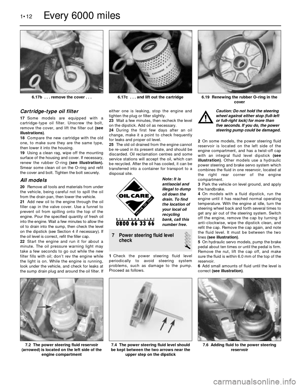
17Some models are equipped with a
cartridge-type oil filter. Unscrew the bolt,
remove the cover, and lift the filter out (see
illustrations).
18Compare the new cartridge with the old
one, to make sure they are the same type,
then lower it into the housing.
19Using a clean rag, wipe off the mounting
surface of the housing and cover. If necessary,
renew the rubber O-ring (see illustration).
Smear some clean oil on the O-ring and refit
the cover and bolt. Tighten the bolt securely.
All models
20Remove all tools and materials from under
the vehicle, being careful not to spill the oil
from the drain pan, then lower the vehicle.
21Add new oil to the engine through the oil
filler cap in the valve cover. Use a funnel to
prevent oil from spilling onto the top of the
engine. Pour the specified quantity of fresh oil
into the engine. Wait a few minutes to allow the
oil to drain into the sump, then check the level
on the dipstick (see Section 4 if necessary). If
the oil level is correct, refit the filler cap.
22Start the engine and run it for about a
minute. The oil pressure warning light may
take a few seconds to go out while the new
filter fills with oil; don’t rev the engine while
the light is on. While the engine is running,
look under the vehicle, and check for leaks at
the sump drain plug and around the oil filter. Ifeither one is leaking, stop the engine and
tighten the plug or filter slightly.
23Wait a few minutes, then recheck the level
on the dipstick. Add oil as necessary.
24During the first few days after an oil
change, make it a point to check frequently
for leaks and proper oil level.
25The old oil drained from the engine cannot
be re-used in its present state, and should be
discarded. Oil reclamation centres and some
service stations will accept the oil, which can
be recycled. After the oil has cooled, it can be
transferred into a container for transport to a
disposal site.
7 Power steering fluid level
check
1
1Check the power steering fluid level
periodically to avoid steering system
problems, such as damage to the pump.
Proceed as follows.Caution: Do not hold the steering
wheel against either stop (full-left
or full-right lock) for more than
five seconds. If you do, the power
steering pump could be damaged.
2On some models, the power steering fluid
reservoir is located on the left side of the
engine compartment, and has a twist-off cap
with an integral fluid level dipstick (see
illustration). Other models use a hydraulic
power steering and brake servo system which
combines the fluid in one reservoir, located at
the right rear corner of the engine
compartment.
3Park the vehicle on level ground, and apply
the handbrake.
4On models with a fluid dipstick, run the
engine until it has reached normal operating
temperature. With the engine at idle, turn the
steering wheel back and forth several times to
get any air out of the steering system. Switch
off the engine, remove the cap by turning it
anti-clockwise, wipe the dipstick clean, and
refit the cap. Remove the cap again, and note
the fluid level. It must be between the two
lines (see illustration).
5On hydraulic servo models, pump the brake
pedal about ten times or until the pedal is firm.
Remove the nut, lift the cap off, and make
sure the fluid is within 6.0 mm of the top of the
reservoir.
6Add small amounts of fluid until the level is
correct (see illustration).
1•12
7.6 Adding fluid to the power steering
reservoir7.4 The power steering fluid level should
be kept between the two arrows near the
upper step on the dipstick7.2 The power steering fluid reservoir
(arrowed) is located on the left side of the
engine compartment
6.19 Renewing the rubber O-ring in the
cover6.17c . . . and lift out the cartridge
Every 6000 miles
6.17b . . . remove the cover . . .
Note: It is
antisocial and
illegal to dump
oil down the
drain. To find
the location of
your local oil
recycling
bank, call this
number free.
Page 31 of 228
4Since some components of the fuel system
- the fuel tank and some of the fuel feed and
return lines, for example - are underneath the
vehicle, they can be inspected more easily
with the vehicle raised on a hoist. If that’s not
possible, raise the vehicle and support it on
axle stands or ramps.
5With the vehicle raised and safely
supported, inspect the fuel tank and filler neck
for punctures, cracks or other damage. The
connection between the filler neck and the
tank is particularly critical. Sometimes a
rubber filler neck will leak because of loose
clamps or deteriorated rubber. Inspect all fuel
tank mounting brackets and straps, to be sure
the tank is securely attached to the vehicle.
Warning: Do not, under any
circumstances, try to repair a fuel
tank (except rubber
components). A welding torch or
any naked flame can easily cause fuel
vapours inside the tank to explode.
6Carefully check all flexible hoses and metal
lines leading away from the fuel tank. Check
for loose connections, deteriorated hoses,
crimped lines, and other damage. Repair or
renew damaged sections as necessary (see
Chapter 4).
22 Cooling system check
1
1Many major engine failures can be
attributed to cooling system problems. If the
vehicle has automatic transmission, the
engine cooling system also plays an importantrole in prolonging transmission life, because it
cools the transmission fluid.
2The engine should be cold for the cooling
system check, so perform the following
procedure before the vehicle is driven for the
day, or after it has been switched off for at
leastthree hours.
3Remove the radiator cap, doing so slowly
and taking adequate precautions against
scalding if the engine is at all warm. Clean the
cap thoroughly, inside and out, with clean
water. Also clean the filler neck on the
radiator. The presence of rust or corrosion in
the filler neck means the coolant should be
changed (see Section 29). The coolant inside
the radiator should be relatively clean and
clear. If it’s rust-coloured, drain the system
and refill with new coolant.
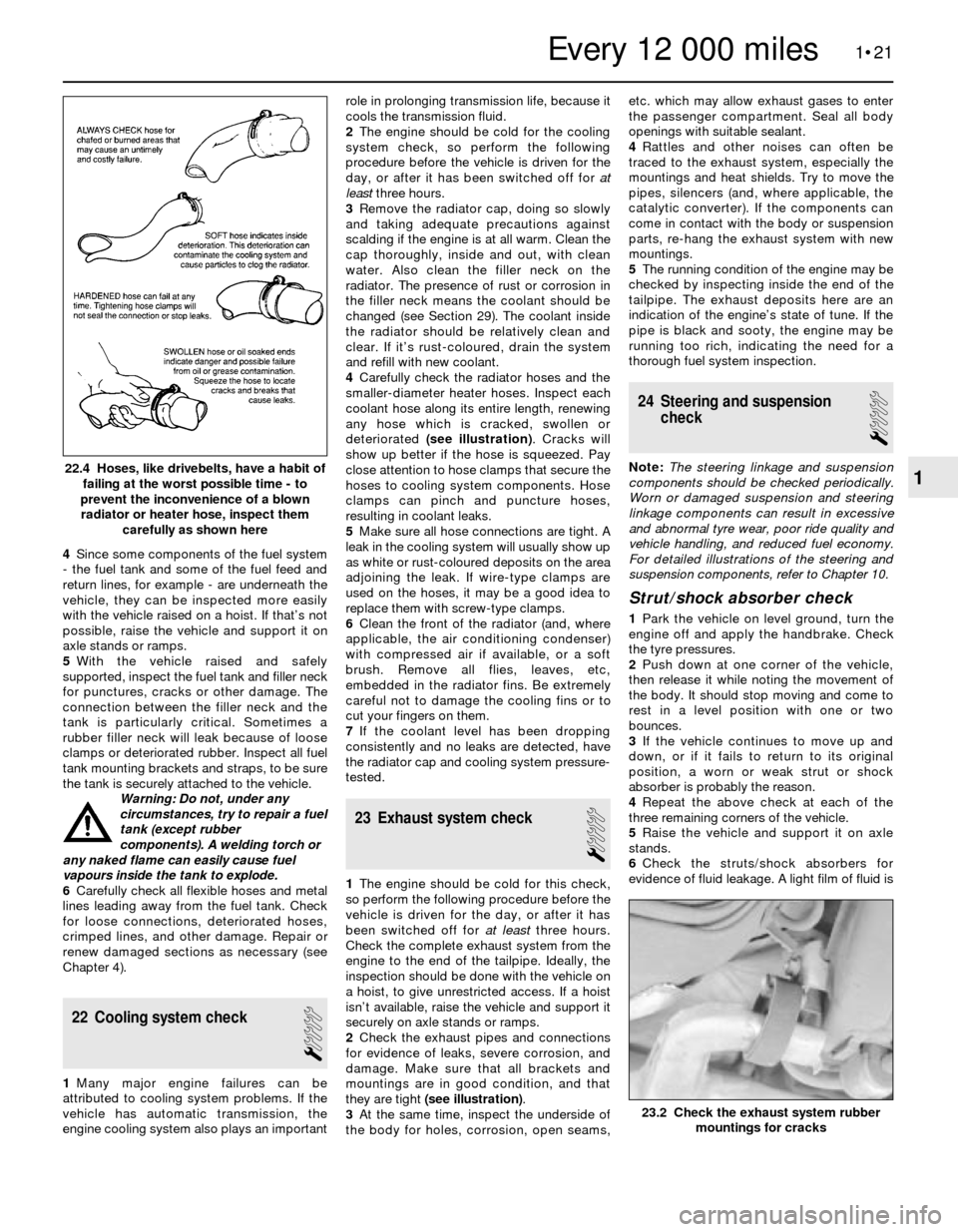
4Carefully check the radiator hoses and the
smaller-diameter heater hoses. Inspect each
coolant hose along its entire length, renewing
any hose which is cracked, swollen or
deteriorated (see illustration). Cracks will
show up better if the hose is squeezed. Pay
close attention to hose clamps that secure the
hoses to cooling system components. Hose
clamps can pinch and puncture hoses,
resulting in coolant leaks.
5Make sure all hose connections are tight. A
leak in the cooling system will usually show up
as white or rust-coloured deposits on the area
adjoining the leak. If wire-type clamps are
used on the hoses, it may be a good idea to
replace them with screw-type clamps.
6Clean the front of the radiator (and, where
applicable, the air conditioning condenser)
with compressed air if available, or a soft
brush. Remove all flies, leaves, etc,
embedded in the radiator fins. Be extremely
careful not to damage the cooling fins or to
cut your fingers on them.
7If the coolant level has been dropping
consistently and no leaks are detected, have
the radiator cap and cooling system pressure-
tested.
23 Exhaust system check
1
1The engine should be cold for this check,
so perform the following procedure before the
vehicle is driven for the day, or after it has
been switched off for at leastthree hours.
Check the complete exhaust system from the
engine to the end of the tailpipe. Ideally, the
inspection should be done with the vehicle on
a hoist, to give unrestricted access. If a hoist
isn’t available, raise the vehicle and support it
securely on axle stands or ramps.
2Check the exhaust pipes and connections
for evidence of leaks, severe corrosion, and
damage. Make sure that all brackets and
mountings are in good condition, and that
they are tight (see illustration).
3At the same time, inspect the underside of
the body for holes, corrosion, open seams,etc. which may allow exhaust gases to enter
the passenger compartment. Seal all body
openings with suitable sealant.
4Rattles and other noises can often be
traced to the exhaust system, especially the
mountings and heat shields. Try to move the
pipes, silencers (and, where applicable, the
catalytic converter). If the components can
come in contact with the body or suspension
parts, re-hang the exhaust system with new
mountings.
5The running condition of the engine may be
checked by inspecting inside the end of the
tailpipe. The exhaust deposits here are an
indication of the engine’s state of tune. If the
pipe is black and sooty, the engine may be
running too rich, indicating the need for a
thorough fuel system inspection.
24 Steering and suspension
check
1
Note: The steering linkage and suspension
components should be checked periodically.
Worn or damaged suspension and steering
linkage components can result in excessive
and abnormal tyre wear, poor ride quality and
vehicle handling, and reduced fuel economy.
For detailed illustrations of the steering and
suspension components, refer to Chapter 10.
Strut/shock absorber check
1Park the vehicle on level ground, turn the
engine off and apply the handbrake. Check
the tyre pressures.
2Push down at one corner of the vehicle,
then release it while noting the movement of
the body. It should stop moving and come to
rest in a level position with one or two
bounces.
3If the vehicle continues to move up and
down, or if it fails to return to its original
position, a worn or weak strut or shock
absorber is probably the reason.
4Repeat the above check at each of the
three remaining corners of the vehicle.
5Raise the vehicle and support it on axle
stands.
6Check the struts/shock absorbers for
evidence of fluid leakage. A light film of fluid is
1•21
22.4 Hoses, like drivebelts, have a habit of
failing at the worst possible time - to
prevent the inconvenience of a blown
radiator or heater hose, inspect them
carefully as shown here
23.2 Check the exhaust system rubber
mountings for cracks
1
Every 12 000 miles
Page 71 of 228
16 Engine block- inspection
3
1Before the block is inspected, it should be
cleaned (see Section 15).
2Visually check the block for cracks, rust
and corrosion. Look for stripped threads in
the threaded holes. It’s also a good idea to
have the block checked for hidden cracks by
a machine shop that has the special
equipment to do this type of work. If defects
are found, have the block repaired, if possible;
otherwise, a new block will be required.
3Check the cylinder bores for scuffing and
scoring.
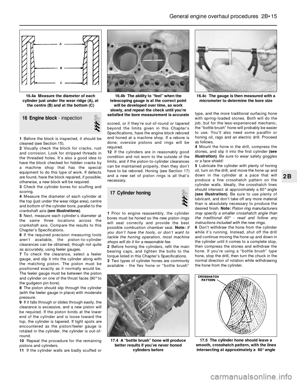
4Measure the diameter of each cylinder at
the top (just under the wear ridge area), centre
and bottom of the cylinder bore, parallel to the
crankshaft axis (see illustrations).
5Next, measure each cylinder’s diameter at
the same three locations across the
crankshaft axis. Compare the results to this
Chapter’s Specifications.
6If the required precision measuring tools
aren’t available, the piston-to-cylinder
clearances can be obtained, though not quite
as accurately, using feeler gauges.
7To check the clearance, select a feeler
gauge, and slip it into the cylinder along with
the matching piston. The piston must be
positioned exactly as it normally would be.
The feeler gauge must be between the piston
and cylinder on one of the thrust faces (90° to
the gudgeon pin bore).
8The piston should slip through the cylinder
(with the feeler gauge in place) with moderate
pressure.
9If it falls through or slides through easily, the
clearance is excessive, and a new piston will
be required. If the piston binds at the lower
end of the cylinder and is loose toward the
top, the cylinder is tapered. If tight spots are
encountered as the piston/feeler gauge is
rotated in the cylinder, the cylinder is out-of-
round.
10Repeat the procedure for the remaining
pistons and cylinders.
11If the cylinder walls are badly scuffed orscored, or if they’re out-of-round or tapered
beyond the limits given in this Chapter’s
Specifications, have the engine block rebored
and honed at a machine shop. If a rebore is
done, oversize pistons and rings will be
required.
12If the cylinders are in reasonably good
condition and not worn to the outside of the
limits, and if the piston-to-cylinder clearances
can be maintained properly, then they don’t
have to be rebored. Honing (see Section 17)
and a new set of piston rings is all that’s
necessary.
17 Cylinder honing
3
1Prior to engine reassembly, the cylinder
bores must be honed so the new piston rings
will seat correctly and provide the best
possible combustion chamber seal. Note:If
you don’t have the tools, or don’t want to
tackle the honing operation, most machine
shops will do it for a reasonable fee.
2Before honing the cylinders, refit the main
bearing caps, and tighten the bolts to the
torque listed in this Chapter’s Specifications.
3Two types of cylinder hones are commonly
available - the flex hone or “bottle brush”type, and the more traditional surfacing hone
with spring-loaded stones. Both will do the
job, but for the less-experienced mechanic,
the “bottle brush” hone will probably be easier
to use. You’ll also need some paraffin or
honing oil, rags and an electric drill. Proceed
as follows.
4Mount the hone in the drill, compress the
stones, and slip it into the first cylinder (see
illustration). Be sure to wear safety goggles
or a face shield!
5Lubricate the cylinder with plenty of honing
oil, turn on the drill, and move the hone up and
down in the cylinder at a pace that will
produce a fine crosshatch pattern on the
cylinder walls. Ideally, the crosshatch lines
should intersect at approximately a 60° angle
(see illustration). Be sure to use plenty of
lubricant, and don’t take off any more material
than is absolutely necessary to produce the
desired finish. Note:Piston ring manufacturers
may specify a smaller crosshatch angle than
the traditional 60°- read and follow any
instructions included with the new rings.
6Don’t withdraw the hone from the cylinder
while it’s running. Instead, shut off the drill
and continue moving the hone up and down in
the cylinder until it comes to a complete stop,
then compress the stones and withdraw the
hone. If you’re using a “bottle brush” type
hone, stop the drill, then turn the chuck in the
normal direction of rotation while withdrawing
the hone from the cylinder.
General engine overhaul procedures 2B•15
16.4c The gauge is then measured with a
micrometer to determine the bore size16.4b The ability to “feel” when the
telescoping gauge is at the correct point
will be developed over time, so work
slowly, and repeat the check until you’re
satisfied the bore measurement is accurate16.4a Measure the diameter of each
cylinder just under the wear ridge (A), at
the centre (B) and at the bottom (C)
17.5 The cylinder hone should leave a
smooth, crosshatch pattern, with the lines
intersecting at approximately a 60° angle17.4 A “bottle brush” hone will produce
better results if you’ve never honed
cylinders before
2B
Page 77 of 228
slowly, and make sure the seal enters the bore
squarely.
5The seal lips must be lubricated with multi-
purpose grease or clean engine oil before the
seal/retainer is slipped over the crankshaft
and bolted to the block (see illustration). Use
a new gasket - no sealant is required - and
make sure the dowel pins are in place before
refitting the retainer.
6Tighten the retainer nuts/screws a little at a
time until they’re all snug, then tighten them to
the torque listed in the Specifications in
Chapter 2A.
26 Pistons/connecting rods-
refitting and big-end bearing
oil clearance check
4
1Before refitting the piston/connecting rod
assemblies, the cylinder walls must be
perfectly clean, the top edge of each cylinder
must be chamfered, and the crankshaft must
be in place.
2Remove the cap from the end of No 1
connecting rod (refer to the marks made
during removal). Remove the original bearing
shells, and wipe the bearing surfaces of the
connecting rod and cap with a clean, lint-free
cloth. They must be kept spotlessly-clean.
Connecting rod big-end bearing
oil clearance check
3Clean the back side of the new upper
bearing shell, then lay it in place in the
connecting rod. Make sure the tab on the
bearing fits into the recess in the rod. Don’t
hammer the bearing shell into place, and be
very careful not to nick or gouge the bearing
face. Don’t lubricate the bearing at this time.
4Clean the back side of the other bearing
shell, and refit it in the rod cap. Again, make
sure the tab on the bearing fits into the recess
in the cap, and don’t apply any lubricant. It’s
critically important that the mating surfaces of
the bearing and connecting rod are perfectlyclean and oil-free when they’re assembled for
this check.
5Position the piston ring gaps so they’re
staggered 120° from each other.
6Where applicable, slip a section of plastic
or rubber hose over each connecting rod cap
bolt.
7Lubricate the piston and rings with clean
engine oil, and attach a piston ring
compressor to the piston. Leave the skirt
protruding about 6 or 7 mm to guide the
piston into the cylinder. The rings must be
compressed until they’re flush with the piston.
8Rotate the crankshaft until the No 1
connecting rod journal is at BDC (bottom
dead centre). Apply a coat of engine oil to the
cylinder walls.
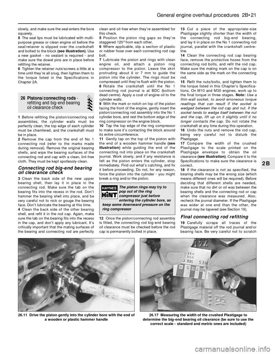
9With the mark or notch on top of the piston
facing the front of the engine, gently insert the
piston/connecting rod assembly into the No 1
cylinder bore, and rest the bottom edge of the
ring compressor on the engine block.
10Tap the top edge of the ring compressor
to make sure it’s contacting the block around
its entire circumference.
11Gently tap on the top of the piston with
the end of a wooden hammer handle (see
illustration)while guiding the end of the
connecting rod into place on the crankshaft
journal. Work slowly, and if any resistance is
felt as the piston enters the cylinder, stop
immediately. Find out what’s catching, and fix
it before proceeding. Do not, for any reason,
force the piston into the cylinder - you might
break a ring and/or the piston.
12Once the piston/connecting rod assembly
is fitted, the connecting rod big-end bearing
oil clearance must be checked before the rod
cap is permanently bolted in place.13Cut a piece of the appropriate-size
Plastigage slightly shorter than the width of
the connecting rod big-end bearing,
and lay it in place on the No 1 connecting rod
journal, parallel with the crankshaft centre-
line.
14Clean the connecting rod cap bearing
face, remove the protective hoses from the
connecting rod bolts, and refit the rod cap.
Make sure the mating mark on the cap is on
the same side as the mark on the connecting
rod.
15Refit the nuts/bolts, and tighten them to
the torque listed in this Chapter’s Specifica-
tions. On M10 and M30 engines, work up to
the final torque in three stages. Note:Use a
thin-wall socket, to avoid erroneous torque
readings that can result if the socket is
wedged between the rod cap and nut. If the
socket tends to wedge itself between the nut
and the cap, lift up on it slightly until it no
longer contacts the cap. Do not rotate the
crankshaft at any time during this operation.
16Undo the nuts and remove the rod cap,
being very careful not to disturb the
Plastigage.
17Compare the width of the crushed
Plastigage to the scale printed on the
Plastigage envelope to obtain the oil
clearance (see illustration). Compare it to the
Specifications to make sure the clearance is
correct.
18If the clearance is not as specified, the
bearing shells may be the wrong size (which
means different ones will be required). Before
deciding that different shells are needed,
make sure that no dirt or oil was between the
bearing shells and the connecting rod or cap
when the clearance was measured. Also,
recheck the journal diameter. If the Plastigage
was wider at one end than the other, the
journal may be tapered (see Section 19).
Final connecting rod refitting
19Carefully scrape all traces of the
Plastigage material off the rod journal and/or
bearing face. Be very careful not to scratch
General engine overhaul procedures 2B•21
26.17 Measuring the width of the crushed Plastigage to
determine the big-end bearing oil clearance (be sure to use the
correct scale - standard and metric ones are included)26.11 Drive the piston gently into the cylinder bore with the end of
a wooden or plastic hammer handle
2B
The piston rings may try to
pop out of the ring
compressor just before
entering the cylinder bore, so
keep some downward pressure on the
ring compressor
Page 101 of 228
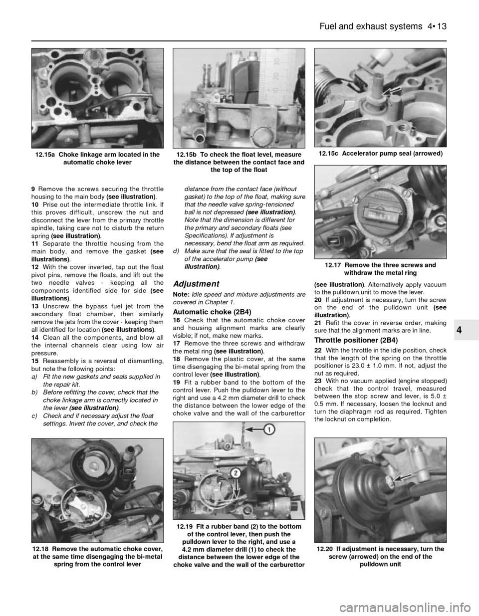
9Remove the screws securing the throttle
housing to the main body (see illustration).
10Prise out the intermediate throttle link. If
this proves difficult, unscrew the nut and
disconnect the lever from the primary throttle
spindle, taking care not to disturb the return
spring (see illustration).
11Separate the throttle housing from the
main body, and remove the gasket (see
illustrations).
12With the cover inverted, tap out the float
pivot pins, remove the floats, and lift out the
two needle valves - keeping all the
components identified side for side (see
illustrations).
13Unscrew the bypass fuel jet from the
secondary float chamber, then similarly
remove the jets from the cover - keeping them
all identified for location (see illustrations).
14Clean all the components, and blow all
the internal channels clear using low air
pressure.
15Reassembly is a reversal of dismantling,
but note the following points:
a) Fit the new gaskets and seals supplied in
the repair kit.
b) Before refitting the cover, check that the
choke linkage arm is correctly located in
the lever (see illustration).
c) Check and if necessary adjust the float
settings. Invert the cover, and check thedistance from the contact face (without
gasket) to the top of the float, making sure
that the needle valve spring-tensioned
ball is not depressed (see illustration).
Note that the dimension is different for
the primary and secondary floats (see
Specifications). If adjustment is
necessary, bend the float arm as required.
d) Make sure that the seal is fitted to the top
of the accelerator pump (see
illustration).
Adjustment
Note:Idle speed and mixture adjustments are
covered in Chapter 1.
Automatic choke (2B4)16Check that the automatic choke cover
and housing alignment marks are clearly
visible; if not, make new marks.
17Remove the three screws and withdraw
the metal ring (see illustration).
18Remove the plastic cover, at the same
time disengaging the bi-metal spring from the
control lever (see illustration).
19Fit a rubber band to the bottom of the
control lever. Push the pulldown lever to the
right and use a 4.2 mm diameter drill to check
the distance between the lower edge of the
choke valve and the wall of the carburettor(see illustration). Alternatively apply vacuum
to the pulldown unit to move the lever.
20If adjustment is necessary, turn the screw
on the end of the pulldown unit (see
illustration).
21Refit the cover in reverse order, making
sure that the alignment marks are in line.
Throttle positioner (2B4)
22With the throttle in the idle position, check
that the length of the spring on the throttle
positioner is 23.0 ± 1.0 mm. If not, adjust the
nut as required.
23With no vacuum applied (engine stopped)
check that the control travel, measured
between the stop screw and lever, is 5.0 ±
0.5 mm. If necessary, loosen the locknut and
turn the diaphragm rod as required. Tighten
the locknut on completion.
Fuel and exhaust systems 4•13
12.15b To check the float level, measure
the distance between the contact face and
the top of the float12.15a Choke linkage arm located in the
automatic choke lever
12.20 If adjustment is necessary, turn the
screw (arrowed) on the end of the
pulldown unit
12.19 Fit a rubber band (2) to the bottom
of the control lever, then push the
pulldown lever to the right, and use a
4.2 mm diameter drill (1) to check the
distance between the lower edge of the
choke valve and the wall of the carburettor
12.17 Remove the three screws and
withdraw the metal ring
12.15c Accelerator pump seal (arrowed)
12.18 Remove the automatic choke cover,
at the same time disengaging the bi-metal
spring from the control lever
4
Page 104 of 228
17 Throttle body- check,
removal and refitting
2
Check
1Detach the air intake duct from the throttle
body (see Section 8) and move the duct out of
the way.
2Have an assistant depress the throttle
pedal while you watch the throttle valve.
Check that the throttle valve moves smoothly
when the throttle is moved from closed (idle
position) to fully-open (wide-open throttle).
3If the throttle valve is not working properly,
renew the throttle body unit.
Warning: Wait until the engine is
completely cool before beginning
this procedure.
Caution: If the radio in your
vehicle is equipped with an anti-
theft system, make sure you
have the correct activation code
before disconnecting the battery. Refer to
the information on page 0-7 at the front of
this manual before detaching the cable.
Note: If, after connecting the battery, the
wrong language appears on the instrument
panel display, refer to page 0-7 for the
language resetting procedure.
Removal and refitting
4Detach the battery negative cable.
5Detach the air intake duct from the throttle
body, and place to one side.
6Detach the accelerator cable from the
throttle body (see Section 9).
7Detach the cruise control cable, if applicable.
8Clearly label all electrical connectors
(throttle position sensor, cold start injector,
idle air stabiliser, etc), then unplug them.
9Clearly label all vacuum hoses, then detach
them.
10Unscrew the radiator or expansion tank
cap to relieve any residual pressure in the
cooling system, then refit it. Clamp shut the
coolant hoses, then loosen the hose clamps
and detach the hoses. Be prepared for some
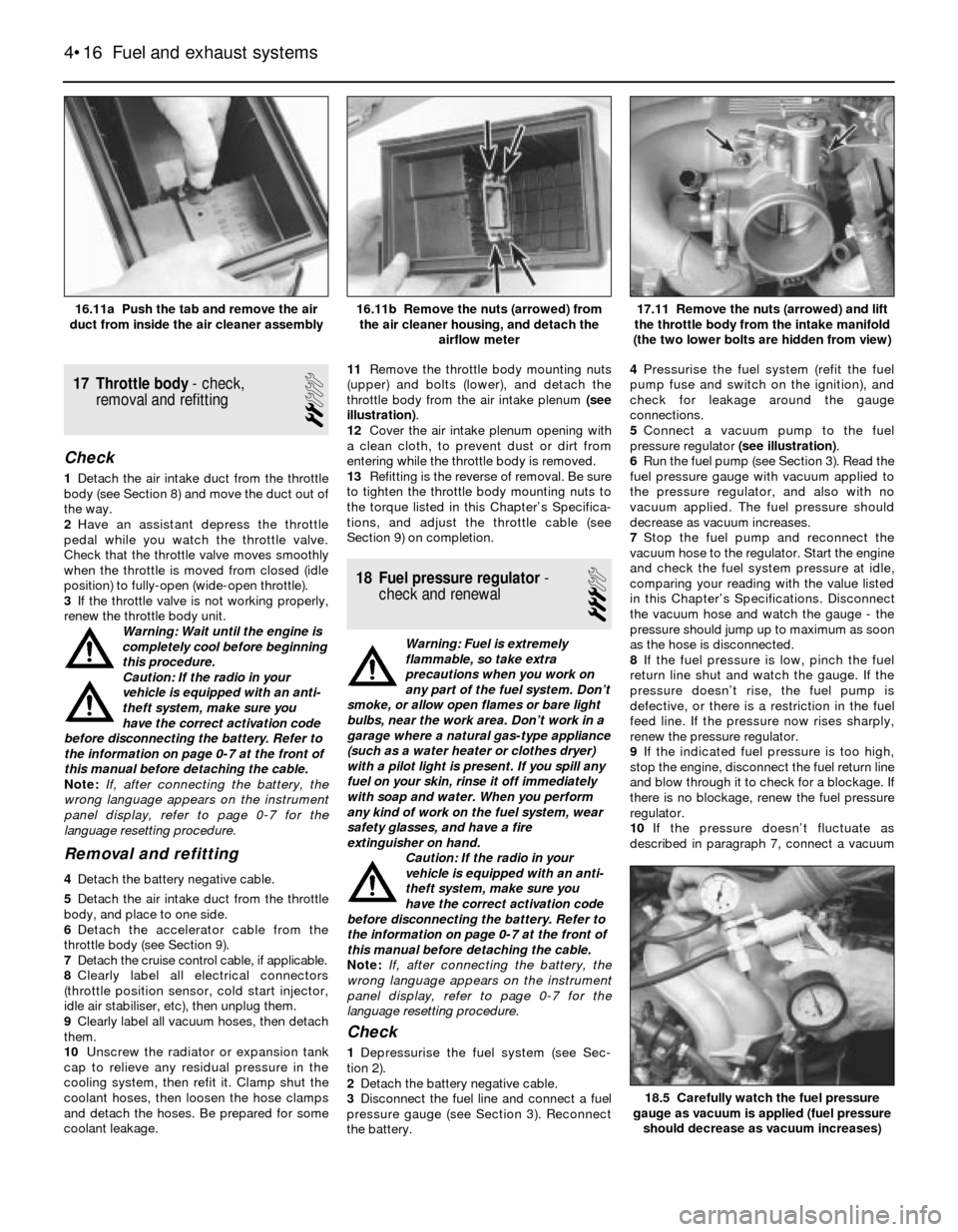
coolant leakage.11Remove the throttle body mounting nuts
(upper) and bolts (lower), and detach the
throttle body from the air intake plenum (see
illustration).
12Cover the air intake plenum opening with
a clean cloth, to prevent dust or dirt from
entering while the throttle body is removed.
13Refitting is the reverse of removal. Be sure
to tighten the throttle body mounting nuts to
the torque listed in this Chapter’s Specifica-
tions, and adjust the throttle cable (see
Section 9) on completion.
18 Fuel pressure regulator-
check and renewal
3
Warning: Fuel is extremely
flammable, so take extra
precautions when you work on
any part of the fuel system. Don’t
smoke, or allow open flames or bare light
bulbs, near the work area. Don’t work in a
garage where a natural gas-type appliance
(such as a water heater or clothes dryer)
with a pilot light is present. If you spill any
fuel on your skin, rinse it off immediately
with soap and water. When you perform
any kind of work on the fuel system, wear
safety glasses, and have a fire
extinguisher on hand.
Caution: If the radio in your
vehicle is equipped with an anti-
theft system, make sure you
have the correct activation code
before disconnecting the battery. Refer to
the information on page 0-7 at the front of
this manual before detaching the cable.
Note: If, after connecting the battery, the
wrong language appears on the instrument
panel display, refer to page 0-7 for the
language resetting procedure.
Check
1Depressurise the fuel system (see Sec-
tion 2).
2Detach the battery negative cable.
3Disconnect the fuel line and connect a fuel
pressure gauge (see Section 3). Reconnect
the battery.4Pressurise the fuel system (refit the fuel
pump fuse and switch on the ignition), and
check for leakage around the gauge
connections.
5Connect a vacuum pump to the fuel
pressure regulator (see illustration).
6Run the fuel pump (see Section 3). Read the
fuel pressure gauge with vacuum applied to
the pressure regulator, and also with no
vacuum applied. The fuel pressure should
decrease as vacuum increases.
7Stop the fuel pump and reconnect the
vacuum hose to the regulator. Start the engine
and check the fuel system pressure at idle,
comparing your reading with the value listed
in this Chapter’s Specifications. Disconnect
the vacuum hose and watch the gauge - the
pressure should jump up to maximum as soon
as the hose is disconnected.
8If the fuel pressure is low, pinch the fuel
return line shut and watch the gauge. If the
pressure doesn’t rise, the fuel pump is
defective, or there is a restriction in the fuel
feed line. If the pressure now rises sharply,
renew the pressure regulator.
9If the indicated fuel pressure is too high,
stop the engine, disconnect the fuel return line
and blow through it to check for a blockage. If
there is no blockage, renew the fuel pressure
regulator.
10If the pressure doesn’t fluctuate as
described in paragraph 7, connect a vacuum
4•16 Fuel and exhaust systems
18.5 Carefully watch the fuel pressure
gauge as vacuum is applied (fuel pressure
should decrease as vacuum increases)
17.11 Remove the nuts (arrowed) and lift
the throttle body from the intake manifold
(the two lower bolts are hidden from view)16.11b Remove the nuts (arrowed) from
the air cleaner housing, and detach the
airflow meter16.11a Push the tab and remove the air
duct from inside the air cleaner assembly
Page 106 of 228
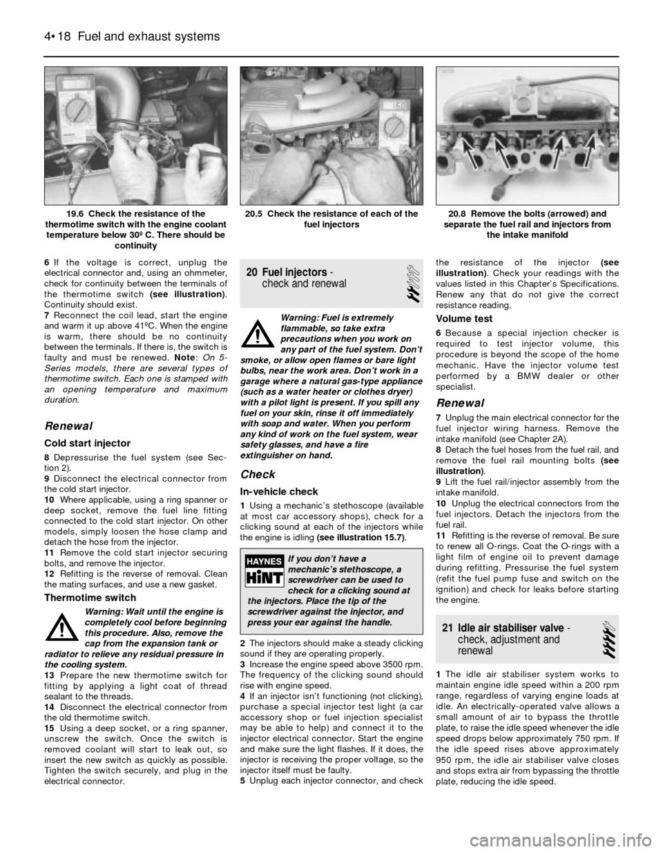
6If the voltage is correct, unplug the
electrical connector and, using an ohmmeter,
check for continuity between the terminals of
the thermotime switch (see illustration).
Continuity should exist.
7Reconnect the coil lead, start the engine
and warm it up above 41ºC. When the engine
is warm, there should be no continuity
between the terminals. If there is, the switch is
faulty and must be renewed. Note: On 5-
Series models, there are several types of
thermotime switch. Each one is stamped with
an opening temperature and maximum
duration.
Renewal
Cold start injector
8Depressurise the fuel system (see Sec-
tion 2).
9Disconnect the electrical connector from
the cold start injector.
10Where applicable, using a ring spanner or
deep socket, remove the fuel line fitting
connected to the cold start injector. On other
models, simply loosen the hose clamp and
detach the hose from the injector.
11Remove the cold start injector securing
bolts, and remove the injector.
12Refitting is the reverse of removal. Clean
the mating surfaces, and use a new gasket.
Thermotime switch
Warning: Wait until the engine is
completely cool before beginning
this procedure. Also, remove the
cap from the expansion tank or
radiator to relieve any residual pressure in
the cooling system.
13Prepare the new thermotime switch for
fitting by applying a light coat of thread
sealant to the threads.
14Disconnect the electrical connector from
the old thermotime switch.
15Using a deep socket, or a ring spanner,
unscrew the switch. Once the switch is
removed coolant will start to leak out, so
insert the new switch as quickly as possible.
Tighten the switch securely, and plug in the
electrical connector.
20 Fuel injectors-
check and renewal
2
Warning: Fuel is extremely
flammable, so take extra
precautions when you work on
any part of the fuel system. Don’t
smoke, or allow open flames or bare light
bulbs, near the work area. Don’t work in a
garage where a natural gas-type appliance
(such as a water heater or clothes dryer)
with a pilot light is present. If you spill any
fuel on your skin, rinse it off immediately
with soap and water. When you perform
any kind of work on the fuel system, wear
safety glasses, and have a fire
extinguisher on hand.
Check
In-vehicle check
1Using a mechanic’s stethoscope (available
at most car accessory shops), check for a
clicking sound at each of the injectors while
the engine is idling (see illustration 15.7).
2The injectors should make a steady clicking
sound if they are operating properly.
3Increase the engine speed above 3500 rpm.
The frequency of the clicking sound should
rise with engine speed.
4If an injector isn’t functioning (not clicking),
purchase a special injector test light (a car
accessory shop or fuel injection specialist
may be able to help) and connect it to the
injector electrical connector. Start the engine
and make sure the light flashes. If it does, the
injector is receiving the proper voltage, so the
injector itself must be faulty.
5Unplug each injector connector, and checkthe resistance of the injector (see
illustration). Check your readings with the
values listed in this Chapter’s Specifications.
Renew any that do not give the correct
resistance reading.
Volume test
6Because a special injection checker is
required to test injector volume, this
procedure is beyond the scope of the home
mechanic. Have the injector volume test
performed by a BMW dealer or other
specialist.
Renewal
7Unplug the main electrical connector for the
fuel injector wiring harness. Remove the
intake manifold (see Chapter 2A).
8Detach the fuel hoses from the fuel rail, and
remove the fuel rail mounting bolts (see
illustration).
9Lift the fuel rail/injector assembly from the
intake manifold.
10Unplug the electrical connectors from the
fuel injectors. Detach the injectors from the
fuel rail.
11Refitting is the reverse of removal. Be sure
to renew all O-rings. Coat the O-rings with a
light film of engine oil to prevent damage
during refitting. Pressurise the fuel system
(refit the fuel pump fuse and switch on the
ignition) and check for leaks before starting
the engine.
21 Idle air stabiliser valve-
check, adjustment and
renewal
4
1The idle air stabiliser system works to
maintain engine idle speed within a 200 rpm
range, regardless of varying engine loads at
idle. An electrically-operated valve allows a
small amount of air to bypass the throttle
plate, to raise the idle speed whenever the idle
speed drops below approximately 750 rpm. If
the idle speed rises above approximately
950 rpm, the idle air stabiliser valve closes
and stops extra air from bypassing the throttle
plate, reducing the idle speed.
4•18 Fuel and exhaust systems
20.8 Remove the bolts (arrowed) and
separate the fuel rail and injectors from
the intake manifold20.5 Check the resistance of each of the
fuel injectors19.6 Check the resistance of the
thermotime switch with the engine coolant
temperature below 30º C. There should be
continuity
If you don’t have a
mechanic’s stethoscope, a
screwdriver can be used to
check for a clicking sound at
the injectors. Place the tip of the
screwdriver against the injector, and
press your ear against the handle.
Page 117 of 228
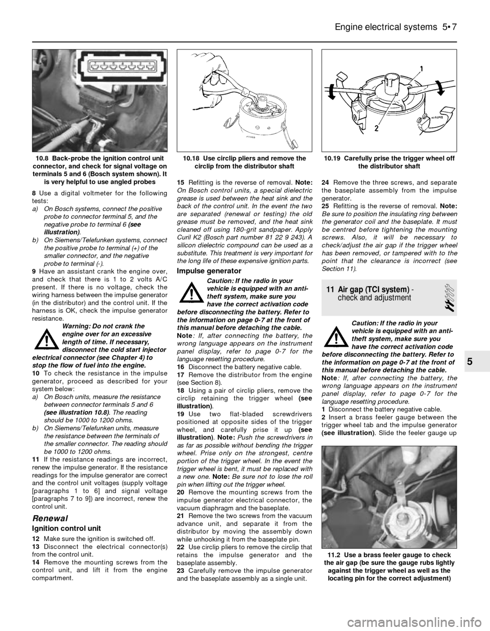
8Use a digital voltmeter for the following
tests:
a) On Bosch systems, connect the positive
probe to connector terminal 5, and the
negative probe to terminal 6 (see
illustration).
b) On Siemens/Telefunken systems, connect
the positive probe to terminal (+) of the
smaller connector, and the negative
probe to terminal (-).
9Have an assistant crank the engine over,
and check that there is 1 to 2 volts A/C
present. If there is no voltage, check the
wiring harness between the impulse generator
(in the distributor) and the control unit. If the
harness is OK, check the impulse generator
resistance.
Warning: Do not crank the
engine over for an excessive
length of time. If necessary,
disconnect the cold start injector
electrical connector (see Chapter 4) to
stop the flow of fuel into the engine.
10To check the resistance in the impulse
generator, proceed as described for your
system below:
a) On Bosch units, measure the resistance
between connector terminals 5 and 6
(see illustration 10.8). The reading
should be 1000 to 1200 ohms.
b) On Siemens/Telefunken units, measure
the resistance between the terminals of
the smaller connector. The reading should
be 1000 to 1200 ohms.
11If the resistance readings are incorrect,
renew the impulse generator. If the resistance
readings for the impulse generator are correct
and the control unit voltages (supply voltage
[paragraphs 1 to 6] and signal voltage
[paragraphs 7 to 9]) are incorrect, renew the
control unit.
Renewal
Ignition control unit
12Make sure the ignition is switched off.
13Disconnect the electrical connector(s)
from the control unit.
14Remove the mounting screws from the
control unit, and lift it from the engine
compartment.15Refitting is the reverse of removal. Note:
On Bosch control units, a special dielectric
grease is used between the heat sink and the
back of the control unit. In the event the two
are separated (renewal or testing) the old
grease must be removed, and the heat sink
cleaned off using 180-grit sandpaper. Apply
Curil K2 (Bosch part number 81 22 9 243). A
silicon dielectric compound can be used as a
substitute. This treatment is very important for
the long life of these expensive ignition parts.
Impulse generator
Caution: If the radio in your
vehicle is equipped with an anti-
theft system, make sure you
have the correct activation code
before disconnecting the battery. Refer to
the information on page 0-7 at the front of
this manual before detaching the cable.
Note: If, after connecting the battery, the
wrong language appears on the instrument
panel display, refer to page 0-7 for the
language resetting procedure.
16Disconnect the battery negative cable.
17Remove the distributor from the engine
(see Section 8).
18Using a pair of circlip pliers, remove the
circlip retaining the trigger wheel (see
illustration).
19Use two flat-bladed screwdrivers
positioned at opposite sides of the trigger
wheel, and carefully prise it up (see
illustration). Note: Push the screwdrivers in
as far as possible without bending the trigger
wheel. Prise only on the strongest, centre
portion of the trigger wheel. In the event the
trigger wheel is bent, it must be replaced with
a new one. Note:Be sure not to lose the roll
pin when lifting out the trigger wheel.
20Remove the mounting screws from the
impulse generator electrical connector, the
vacuum diaphragm and the baseplate.
21Remove the two screws from the vacuum
advance unit, and separate it from the
distributor by moving the assembly down
while unhooking it from the baseplate pin.
22Use circlip pliers to remove the circlip that
retains the impulse generator and the
baseplate assembly.
23Carefully remove the impulse generator
and the baseplate assembly as a single unit.24Remove the three screws, and separate
the baseplate assembly from the impulse
generator.
25Refitting is the reverse of removal. Note:
Be sure to position the insulating ring between
the generator coil and the baseplate. It must
be centred before tightening the mounting
screws. Also, it will be necessary to
check/adjust the air gap if the trigger wheel
has been removed, or tampered with to the
point that the clearance is incorrect (see
Section 11).
11 Air gap (TCI system)-
check and adjustment
2
Caution: If the radio in your
vehicle is equipped with an anti-
theft system, make sure you
have the correct activation code
before disconnecting the battery. Refer to
the information on page 0-7 at the front of
this manual before detaching the cable.
Note: If, after connecting the battery, the
wrong language appears on the instrument
panel display, refer to page 0-7 for the
language resetting procedure.
1Disconnect the battery negative cable.
2Insert a brass feeler gauge between the
trigger wheel tab and the impulse generator
(see illustration). Slide the feeler gauge up
Engine electrical systems 5•7
10.19 Carefully prise the trigger wheel off
the distributor shaft10.18 Use circlip pliers and remove the
circlip from the distributor shaft10.8 Back-probe the ignition control unit
connector, and check for signal voltage on
terminals 5 and 6 (Bosch system shown). It
is very helpful to use angled probes
11.2 Use a brass feeler gauge to check
the air gap (be sure the gauge rubs lightly
against the trigger wheel as well as the
locating pin for the correct adjustment)
5