wheel BMW 318i 1997 E36 Workshop Manual
[x] Cancel search | Manufacturer: BMW, Model Year: 1997, Model line: 318i, Model: BMW 318i 1997 E36Pages: 759
Page 438 of 759
620-2
INSTRUMENTS
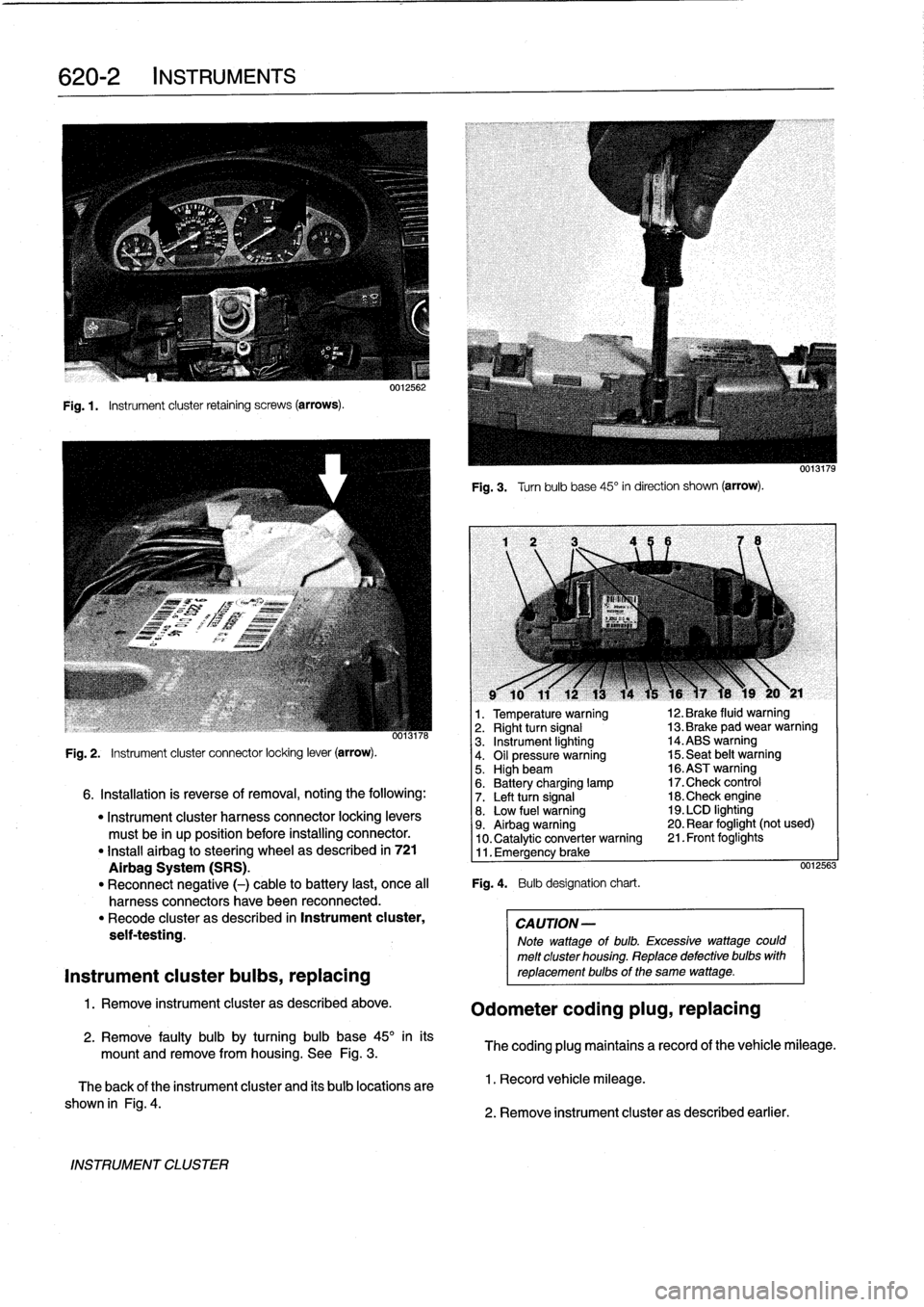
Fig
.1.
Instrument
cluster
retaining
screws
(arrows)
.
INSTRUMENT
CLUSTER
0012562
Fig
.
3
.
Turnbulb
base
45°
in
direction
shown
(arrow)
.
l
v
w
r
v
9
10
11
12
13
14
15
16
)7
18
19
20
y
21
1
.
Temperature
warning
12
.
Brake
fluid
warning
oo13n6
2
.
Right
turn
signal
13
.
Brake
pad
wear
warning
3
.
Instrument
lighting
14
.ABS
warning
Fig
.
2
.
Instrument
cluster
connector
locking
lever
(arrow)
.
4
.
Oil
pressure
warning
15
.
Seat
belt
warning5
.
Highbeam
16
.ASTwarning
6
.
Battery
charging
lamp
17
.Check
control
6
.
Installation
is
reverse
of
removal,
noting
the
following
:
7
.
Left
turn
signal
18
.Check
engine
"
Instrument
cluster
harness
connector
locking
levers
8
.
Low
fuel
warning
19
.
LCD
lighting
must
be
in
up
position
before
installing
connector
.
9
.
Airbag
warning
20
.
Rear
foglight
(not
used)
10
.
Catalytic
converter
warning
21
.
Front
foglights
"
Install
airbag
to
steering
wheel
as
described
in
721
11
.
Emergency
brake
Airbag
System
(SRS)
.
0012563
"
Reconnect
negative
(-)
cable
to
battery
last,
once
al¡
Fig
.
4
.
Bulb
designation
chart
.
harness
connectors
have
been
reconnected
.
"
Recode
cluster
as
described
in
Instrument
cluster,
CAUTION-
seif-testing
.
Note
wattage
of
bulb
.
Excessive
wattage
could
melt
cluster
housing
.
Replace
defective
bulbs
with
Instrument
cluster
bulbs,
replacing
reptacementbulbs
of
the
same
wattage
.
1
.
Remove
instrument
cluster
as
described
above
.
Odometer
coding
plug,
replacing
2
.
Remove
faulty
bulb
by
turning
bulb
base
45°
inits
mount
and
remove
from
housing
.
See
Fig
.
3
.
The
coding
plug
maintains
a
record
of
thevehicle
mileage
.
The
back
of
the
instrument
cluster
and
its
bulb
locations
are
1
.
Record
vehicle
mileage
.
shown
in
Fig
.
4
.
2
.
Remove
instrument
cluster
as
described
earlier
.
Page 449 of 759
9
.
Release
blower
motor
retaining
strap
andremove
blow-
er
motor
and
fans
fromcowl
opening
.
NOTE-
Twist
and
rotate
blowermotor
assembly
to
facilítate
re-
moval
from
opening
.
If
the
blower
motor
is
to
be
rein-stafled,
use
care
not
to
damage
fan
wheels
during
removal
.
ff
the
blower
motor
fs
to
be
replaced,
cut
offfan
wheels
at
center
to
aid
in
removal
.
10
.
Installation
is
reverse
of
removal
.
When
installing
a
re-
placement
blower
motor,
instan
motor
into
cowlarea
before
installing
fan
wheels
.
Blower
motor
test
specifi-
cations
are
listed
in
Table
a
.
NOTE
-
On
replacementblowermotors
from
BMW,
thefan
wheels
come
unattached
to
aid
in
installation
.
Locatearrow
on
blower
motor
and
instan
fan
wheels
atthis
po-
sition
.
Be
sure
color
coolng
matches
.
Retain
fan
wheels
using
the
new
clips
.
See
an
authorized
BMW
parts
de-
partment
for
the
latest
parts
information
.
Table
a
.
Blower
Motor
Test
Values
Testingvoltage
13
VDC
Operating
voltage
9-15
VDC
Max
.
current
consumption
(approx
.)
12
amps
Maximum
speed
3,600-4,000rpm
Axialplay
(max
.
allowable)
1
.0
mm
(0
.04
in
.)
Blower
motor
resistor
pack,
replacing
The
blower
resistor
pack
is
clipped
into
the
upper
left
side
of
theheater
box
.
1
.
Remove
lower
left
dash
trim
panel
.
See513
Interior
Trim
.
2
.
Working
under
left
(driver's)
side
of
dash,
unclip
and
pulí
out
resistor
pack
from
sideof
heater
box
.
Remove
harness
connector
from
resistor
pack
.
See
Fig
.
7
.
3
.
Installation
is
reverse
of
removal
.
Heater
valve,
replacing
The
two-way
heater
valve
is
located
in
the
rear
of
the
engine
compartment
on
the
driver
side
.
The
solenoid
operated
valves
control
the
coolant
flow
through
the
dual-chamber
heater
core
.
1
.
Drain
engine
coolant
.
See
170
Radiator
and
Cooling
System
.
HEATING
AND
AIR
CONDITIONING
640-
3
uuiGO4I
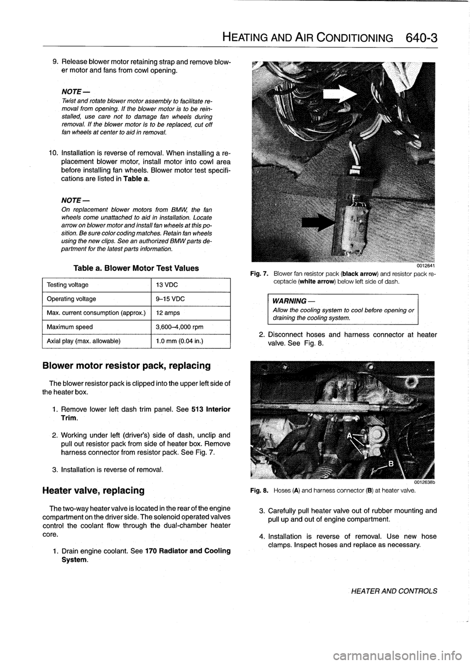
Fig
.
7
.
Blower
fan
resistor
pack
(black
arrow)
and
resistor
pack
re-
ceptacle
(white
arrow)
below
left
sideof
dash
.
WARNING
-
Allow
the
cooling
system
to
cool
before
opening
ordraining
the
cooling
system
.
2
.
Disconnect
hoses
and
harness
connector
at
heater
valve
.
See
Fig
.
8
.
001[ó38b
Fig
.
S
.
Hoses
(A)
and
harnessconnector
(B)
at
heatervalve
.
3
.
Carefully
pull
heater
valve
out
of
rubber
mounting
and
pull
up
and
out
of
engine
compartment
.
4
.
Installation
is
reverse
of
removal
.
Use
new
hose
clamps
.
Inspect
hoses
and
replace
asnecessary
.
HEATER
AND
CONTROLS
Page 477 of 759
721
Airbag
System
(SRS)
Airbag
Systems
.......
.
...
.
.
.
.
.
....
.
.
.
.
721-1
AIRBAG
SENSORS
AND
ELECTRONICS
721-2
SRS
Warning
Light
and
Fault
Display
.
.
.
.
.
..
721-2
Airbagcontact
ring,
replacing
........
.
.
.
.
.
721-3
Airbag
crash
sensor,replacing
..
.
....
.
...
.
721-4
ZAE
control
module,
replacing
.
.
.
.........
721-5
GENERAL
This
repair
group
covers
only
removal
and
installation
of
air-
bag
components
.
Airbag
system
repair
and
fault
diagnosis
is
not
covered
here
.
Diagnostics,
component
testing,
and
airbag
system
repair
should
be
carried
out
by
trained
BMW
service
technicians
.
NOTE-
Special
test
equipment
is
required
to
retrieve
SRS
fault
codes,
diagnose
system
faults,
and
resetltum
off
the
SRS
indicator
light
.
The
SRS
indicator
light
will
remain
on
until
any
problem
has
been
corrected
and
the
fault
memory
has
been
cleared
.
When
servicing
cars
equipped
with
SRS,
the
precautions
on
this
page
mustbeobserved
to
prevent
personal
injury
.
Airbag
Systems
The
airbag
system
installed
on
E36
cars
through
the
1993
model
year
consisted
of
a
single
airbag
in
the
steering
wheel
.
This
systemcan
be
identified
by
the
orange
crash
sensors
lo-
cated
on
the
front
wheel
wells
and
the
absence
of
a
passenger
side
airbag
.
The
ZAE
airbag
system,
starting
in
model
year
1994
(pro-
duction
date9/93
and
later),
provides
both
a
driver
side
and
a
passenger
sideairbag
.
On
ZAE
vehicles,
the
crash
sensorsare
integrated
into
the
airbag
control
module,
located
under
thecenter
of
the
rear
seat
.
The
ZAE
control
module
triggers
deployment
of
the
airbags
When
it
sensos
the
vehicle
deceler-
ating
at
a
rate
equivalent
to
a
head-on
collisionof
at
least
13
mph
(18
km/h)
.
In
some
1997
4-door
models
and
all
1998
models,
side-impact
airbags
were
installed
in
the
front
doors
.
The
airbag
units
are
mounted
behindthe
door
trim
panels
.
Caution
mustbeused
when
working
on
vehicle
systems
in
the
proximity
of
air
bags,
such
as
the
steering
column,
the
dashboard,
or
the
doors
.
AIRBAG
SYSTEM
(SRS)
721-1
GENERAL
.
.
.
.
.
.
.
.
.
.
.......
.
......
.
.
.
.
721-1
Front
side-impact
airbag
crash
sensor,
removing
and
installing
....
.
.....
.
.....
.
721-5
AIRBAGS
..............
.
.
.
.
.
.
.
.
.
.
.
.
.
.
.
721-5
Driver
side
airbag,
removing
and
installing
.
.
.
721-5
Passenger
side
airbag,
removing
and
installing
..............
.
.
.721-6
Front
side-impact
airbag,
removing
and
installing
.
.
.
.
.
.
.
.
.
.
......
.721-7
WARNING
-
"
Airbag(s)
are
inflated
byan
explosive
device
.
Handled
improperly
or
without
adequate
safe-
guards,
the
System
can
be
very
dangerous
.
Spe-
cial
precautions
must
be
observed
prior
to
any
work
ator
near
the
driverside
airbag,
the
passen-
ger
side
airbag
(where
applicable)
or
the
side-im-
pact
airbags
(where
applicable)
.
"
The
airbag
is
a
vehicle
safety
system
.
Serious
in-
jury
may
result
if
System
service
is
attempted
by
persons
unfamiliar
with
the
BMW
SRS
and
its
ap-
proved
service
procedures
.
BMW
advises
that
all
inspection
and
service
be
performed
by
an
autho-
rized
BMW
dealer
.
"
Always
disconnect
the
battery
and
cover
the
neg-
ative
()
battery
terminal
with
an
insulator
before
startingdiagnostic,
troubleshooting
or
service
worknot
associated
with
SRS,
and
before
doing
any
welding
on
the
car
.
"
If
an
airbag
has
been
activated
due
to
an
acci-dent,
BMW
specifies
that
SRS
components
be
replaced
.
For
more
information
on
post-collision
SRS
service,
see
an
authorized
BMW
dealer
.
"
Do
not
allow
the
airbag
unit
to
come
in
contact
with
cleaning
solutions
orgrease
.
Never
subject
an
airbag
unit
to
temperatures
aboye
212°F
(100°C)
.
When
reconnecting
the
battery,
no
per-
son
should
be
inside
the
vehicle
.
"
Always
place
an
airbag
unitthat
has
been
re-
moved
from
its
packaging
with
the
padded
sidefacing
upward
.
Do
not
leave
an
airbag
unlt
unat-
tended
.
"
!f
the
airbag
unit
or
airbag
control
modulehas
been
dropped
froma
height
of
!
1
2
meter
(1
Y2
ft.)
ormore,
theairbag
unit
should
not
be
installed
.
Aírbag
system
components
are
shown
in
Fig
.
1.
GENERAL
Page 478 of 759
721-2
AIRBAG
SYSTEM
(SRS)
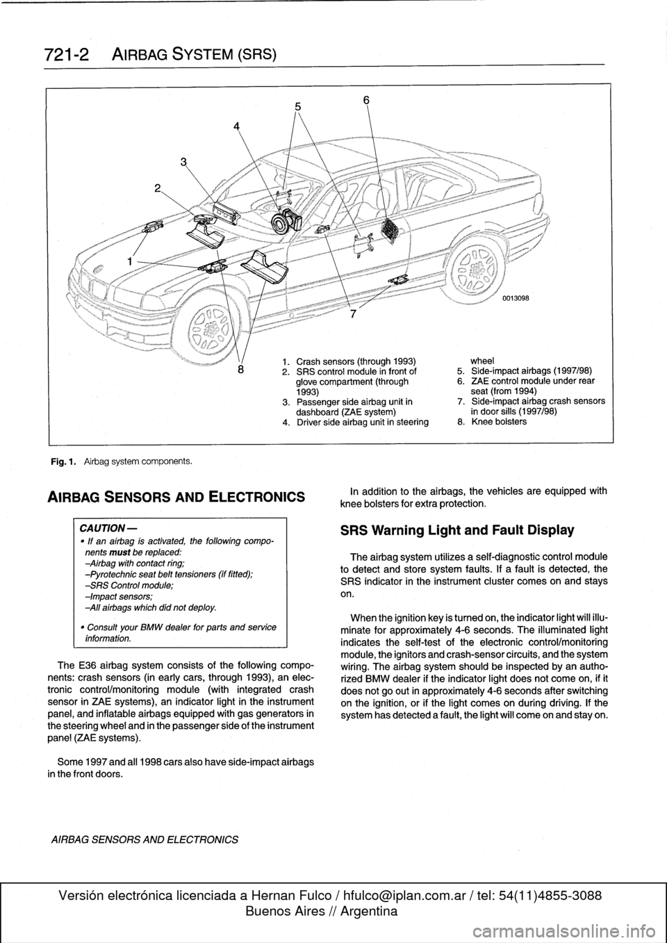
Fig
.
1
.
Airbag
system
components
.
AIRBAG
SENSORSAND
ELECTRONICS
CA
UTION-
"
If
an
airbag
is
activated,
the
following
compo-
nents
must
be
replaced
:
Airbag
with
contact
ring
;
-Pyrotechnic
seat
belt
tensioners
(if
fitted)
;
-SRS
Control
module
;
-Impact
sensors
;
All
airbags
which
did
not
deploy
.
"
Consult
your
BMW
dealer
for
parts
and
service
information
.
TheE36
airbag
system
consists
of
the
following
compo-
nents
:
crash
sensors
(in
earlycars,
through
1993),
an
elec-
tronic
control/monitoring
module
(with
integrated
crash
sensor
in
ZAE
systems),
an
indicator
light
in
the
instrument
panel,
and
inflatable
airbags
equipped
with
gas
generators
in
the
steering
wheel
and
in
the
passenger
side
of
the
instrument
panel
(ZAE
systems)
.
Some
1997
and
al¡
1998
carsalso
have
side-impact
airbags
in
the
front
doors
.
AIRBAG
SENSORS
AND
ELECTRONICS
1.
Crash
sensors
(through
1993)
wheel
2
.
SRS
control
module
in
front
of
5
.
Side-impact
airbags
(1997/98)
glove
compartment
(through
6
.
ZAE
control
module
under
rear
1993)
seat
(from
1994)
3
.
Passenger
side
airbag
unit
in
7
.
Side-impact
airbag
crash
sensors
dashboard
(ZAE
system)
in
door
silis
(1997/98)
4
.
Driver
side
airbag
unitin
steering
8
.
Knee
bolsters
In
addition
to
the
airbags,
the
vehicles
are
equipped
wíth
knee
bolsters
for
extra
protection
.
SRS
Warning
Light
and
Fault
Display
The
airbag
system
utilizes
a
self-diagnostic
control
module
to
detect
and
store
system
faults
.
If
a
fault
is
detected,
the
SRS
indicator
in
the
instrument
cluster
comes
on
and
stays
on
.
When
the
ignition
key
is
tumed
on,
the
indicator
light
will
illu-
minate
for
approximately
4-6
seconds
.
The
illuminated
light
indicates
the
self-testof
the
electronic
control/monitoring
module,
the
ignítors
and
crash-sensorcircuits,
and
the
system
wiring
.
The
airbag
system
should
be
inspected
byan
autho-
rized
BMW
dealer
if
the
indicator
light
does
not
come
on,
ifit
does
not
go
out
in
approximately
4-6
seconds
after
switching
onthe
ignition,
or
if
the
light
comes
on
during
driving
.
If
the
system
has
detected
a
fault,
the
light
will
come
on
and
stay
on
.
Page 479 of 759
1
.
Disconnect
negative
(-)
cable
from
battery
and
cover
negative
terminal
with
insulating
material
.
CA
UTION-
Prior
to
disconnectiog
the
battery,
read
the
battery
disconnection
cautions
given
at
the
front
of
this
manual
on
page
viii
.
2
.
Remove
driver
sideairbag
from
steering
wheel
.
See
Driver
side
airbag,
removing
and
installing
in
this
repair
group
.
3
.
With
wheels
facing
straight
ahead
and
steering
wheel
centered,
remove
steering
wheel
.
See320
Steering
and
Wheel
Alignment
.
4
.
Remove
contact
ring
cover
(flat
plastic
ring
containing
warning
text)
from
steering
wheel,
íf
applicable
.
5
.
Disconnect
ground
wire,
if
applicable
6
.
Lift
out
plastic
lock
from
steering
wheel,
if
applicable
.
See
Fig
.
2
.
0011903
Fig
.
2
.
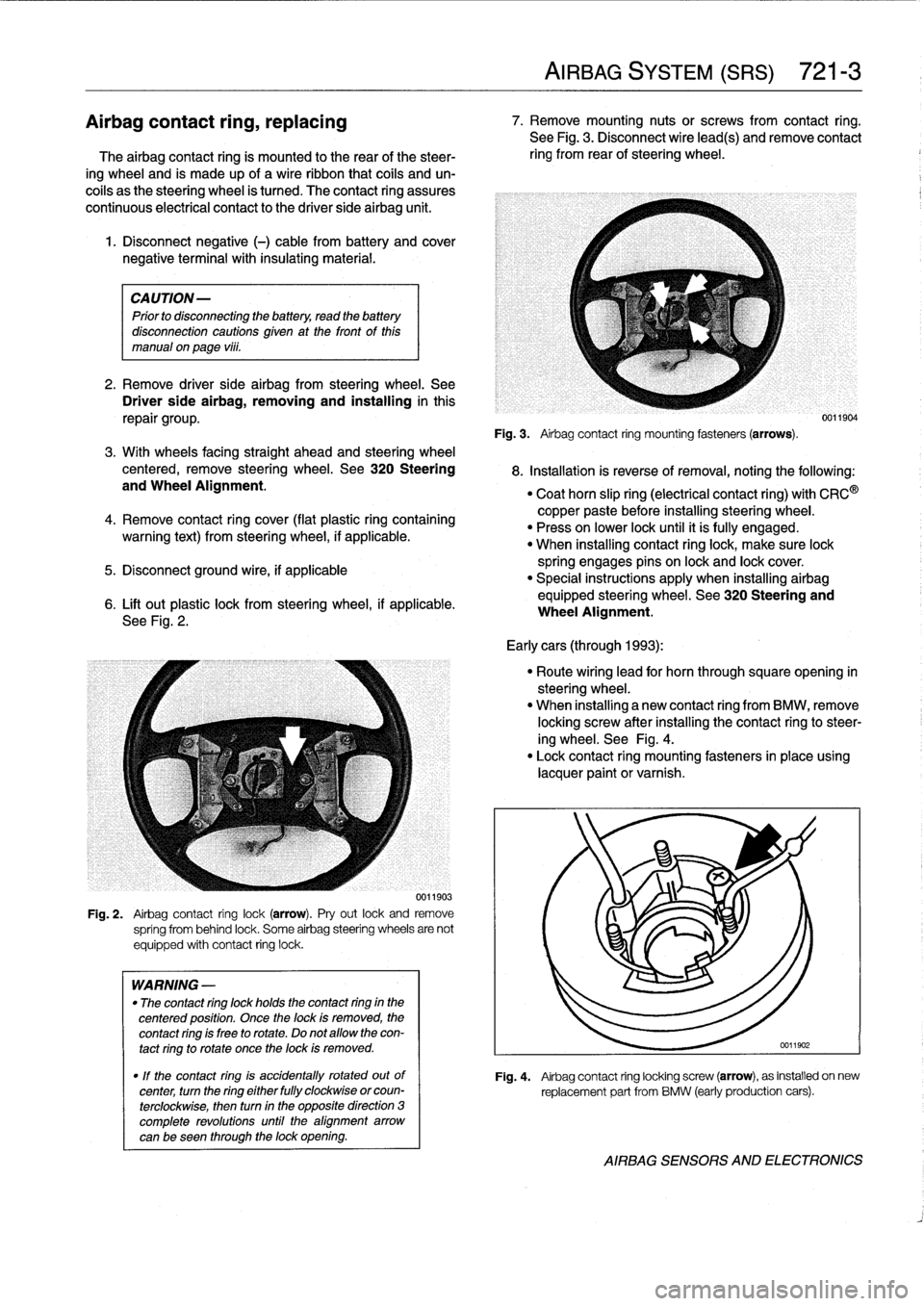
Airbag
contact
ring
lock(arrow)
.
Pry
out
lock
and
remove
spríng
from
behind
lock
.
Some
airbag
steering
wheels
are
not
equipped
with
contact
ring
lock
.
WARNING
-
"
The
contact
ring
lock
holds
the
contact
ring
in
the
centered
position
.
Once
the
lock
is
removed,
the
contact
ring
is
free
to
rotate
.
Do
not
allow
the
con-
tact
ring
to
rotate
once
the
lock
is
removed
.
"
If
the
contact
ring
is
accidentally
rotated
outof
center,
turn
the
ring
either
fully
clockwise
orcoun-
terclockwise,
then
turn
in
the
opposite
direction
3
complete
revolutions
until
the
alignment
arrow
canbe
seen
through
the
lock
opening
.
AIRBAG
SYSTEM
(SRS)
721-
3
Airbagcontact
ring,
replacing
7
.
Remove
mounting
nutsor
screws
from
contact
ring
.
See
Fig
.
3
.
Disconnect
wire
lead(s)
andremove
contact
The
airbag
contact
ring
is
mounted
to
the
rear
of
the
steer-
ring
from
rear
of
steering
wheel
.
ing
wheel
and
is
made
up
of
a
wireribbon
that
cofs
and
un-
coils
as
the
steering
wheel
is
tumed
.
The
contact
ring
assures
continuous
electrical
contact
to
the
driver
side
airbag
unit
.
Fig
.
3
.
Airbag
contact
ring
mounting
fasteners(arrows)
.
8
.
Installation
is
reverse
ofremoval,noting
the
following
:
"
Coat
horn
slip
ring
(electrical
contact
ring)
with
CRC
®
copper
paste
before
installing
steering
wheel
.
"
Press
on
lower
lock
until
it
ís
fully
engaged
.
"
When
installing
contact
ringlock,
make
sure
lock
spring
engages
pins
on
lock
and
lock
cover
.
"
Special
instructions
apply
when
installing
airbag
equipped
steering
wheel
.
See320
Steering
and
Wheel
Alignment
.
Early
cars
(through
1993)
:
"
Route
wiring
lead
for
horn
through
squareopening
in
steering
wheel
.
"
When
installing
a
new
contact
ring
from
BMW,
remove
locking
screw
after
installing
the
contact
ringto
steer-
ing
wheel
.
See
Fig
.
4
.
"
Lock
contact
ring
mounting
fasteners
in
place
using
lacquer
paint
or
varnish
.
0011904
Fig
.
4
.
Airbag
contact
ring
locking
screw
(arrow),
as
installed
on
new
replacement
part
from
BMW
(early
production
cars)
.
AIRBAG
SENSORS
AND
ELECTRONICS
Page 480 of 759
721-
4
AIRBAG
SYSTEM
(SRS)
CAUTION-
A
new
contact
ring
is
held
in
center
position
with
a
screw
.
This
locking
device
must
be
removed
after
contact
ring
is
installed
on
steering
wheel
.
See
Fig
.
4
.
Latercars
(1994
on)
:
"
Connect
ground
lead
at
contact
ring
.
"
When
installing
a
new
contact
ring
from
BMW,
remove
locking
pin
after
installing
contact
ring
to
steering
wheel
.
See
Fig
.
5
.
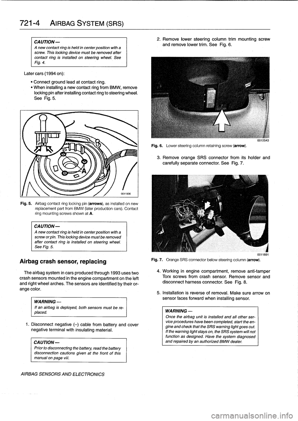
Airbag
crash
sensor,
replacing
Fig
.
5
.
Airbag
contact
ring
locking
pin
(arrows),
as
installed
on
new
replacement
part
from
BMW
(later
production
cars)
.
Contact
ring
mountíng
screws
shown
at
A
.
CAUTION-
Anew
contact
ring
is
held
in
center
position
with
a
screw
or
pin
.
This
locking
device
mustbe
removed
after
contact
ring
is
installed
on
steering
wheel
.
See
Fig
.
5
.
The
airbag
system
in
cars
produced
through
1993
uses
two
crash
sensors
mounted
in
the
engine
compartment
on
the
left
and
right
wheel
arches
.
The
sensors
are
identified
by
their
or-
ange
color
.
WARNING
-
If
en
airbag
is
deployed,
both
sensors
must
be
re-
placed
.
1
.
Disconnect
negative
(-)
cable
from
battery
and
cover
negative
terminal
with
insulating
material
.
CAUTION-
Prior
to
disconnectiog
the
battery,
read
the
battery
disconnection
cautíons
given
at
the
front
of
thls
manual
on
page
viii
.
AIRBAG
SENSORS
AND
ELECTRONICS
2
.
Remove
lower
steering
column
trim
mounting
screw
and
remove
lower
trim
.
See
Fig
.
6
.
Fig
.
6
.
Lower
steering
column
retaining
screw
(arrow)
.
3
.
Remove
orange
SRS
connector
from
its
holder
and
carefully
separate
connector
.
See
Fig
.
7
.
Fig
.
7
.
Orange
SRS
connector
below
steering
column
(arrow)
.
4
.
Working
in
engine
compartment,
remove
anti-tamper
Torx
screwsfrom
crash
sensor
.
Remove
sensor
and
disconnect
harness
connector
.
See
Fig
.
8
.
5
.
Installation
is
reverse
of
removal
.
Make
sure
arrow
on
sensor
faces
forward
when
installing
sensor
.
WARNING
-
Once
the
airbag
unit
is
installed
and
all
other
ser-vice
procedures
have
been
completed,
start
the
en-
gine
and
check
that
the
SRS
warning
light
goes
out
.
If
the
warning
light
stays
on,the
SRS
system
will
not
function
as
designed
.
Have
the
system
diagnosed
and
repaired
byen
authorized
BMW
dealer
.
0012543
0011891
Page 481 of 759
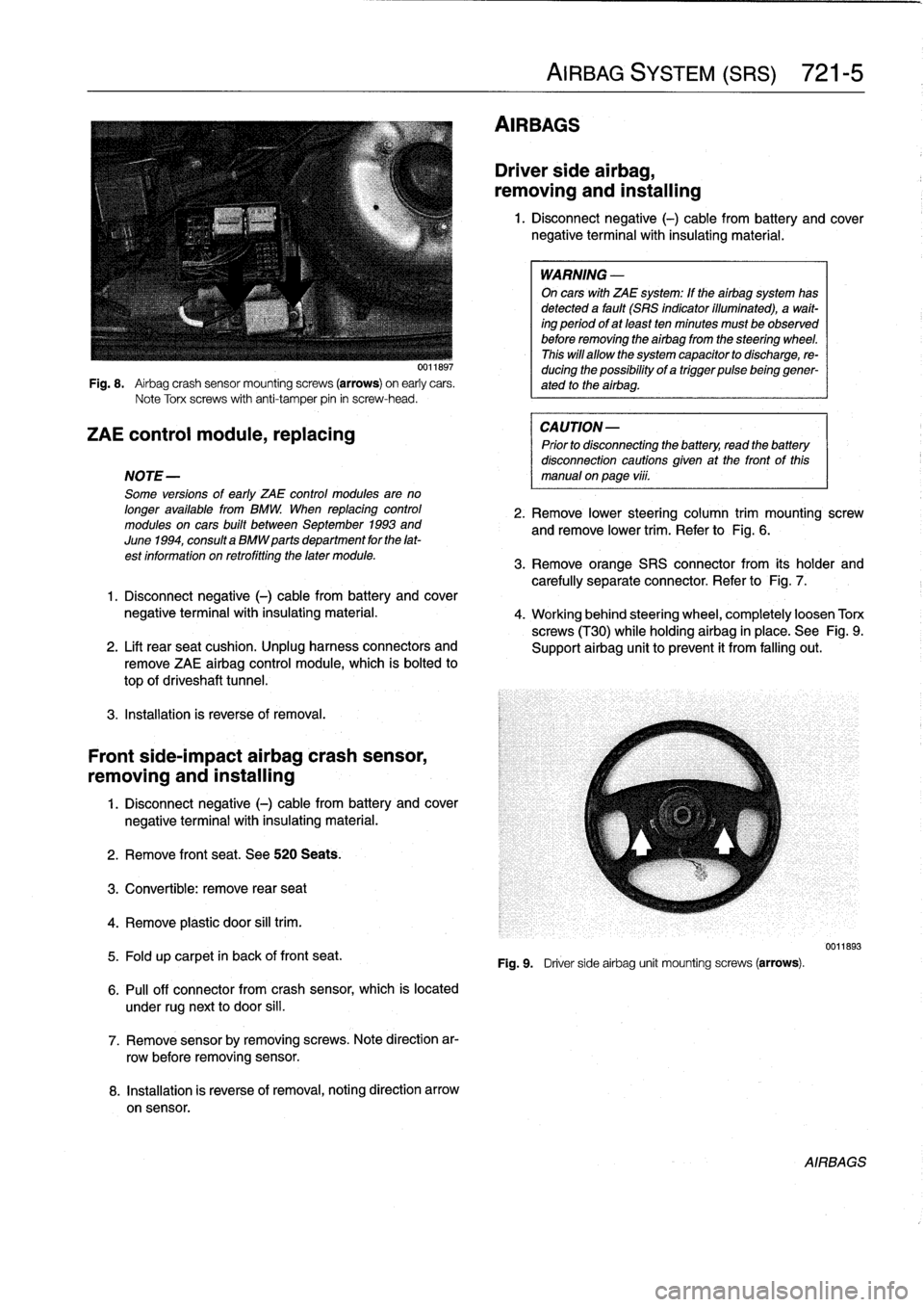
Fig
.
8
.
Airbag
crash
sensor
mountingscrews
(arrows)
on
early
cars
.
Note
Torx
screws
with
anti-tamper
pin
in
screw-head
.
ZAE
control
module,
replacing
NOTE-
Some
versions
of
early
ZAE
control
modules
are
no
longer
available
from
BMW
.
When
replacing
control
modules
on
cars
built
between
September
1993
and
June
1994,
consulta
BMW
parts
department
for
the
lat-
est
information
on
retrofitting
the
later
module
.
3
.
Remove
orange
SRS
connector
from
its
holder
and
carefully
separate
connector
.
Refer
to
Fig
.
7
.
1
.
Disconnect
negative
(-)
cable
from
battery
and
cover
negative
terminalwith
insulating
material
.
4
.
Working
behind
steering
wheel,
completely
loosen
Torx
screws
(T30)
while
holdingairbag
in
place
.
See
Fig
.
9
.
2
.
Lift
rearseat
cushion
.
Unplug
harness
connectors
and
Support
airbag
unit
toprevent
it
from
falling
out
.
remove
ZAE
airbag
control
module,
which
is
bolted
to
top
of
driveshaft
tunnel
.
3
.
Installation
is
reverse
of
removal
.
Front
side-impact
airbag
crash
sensor,
removing
and
installing
1
.
Disconnect
negative
(-)
cable
from
battery
and
cover
negative
terminal
with
insulating
material
.
2
.
Remove
front
seat
.
See520
Seats
.
3
.
Convertible
:
remove
rear
seat
4
.
Remove
plastic
door
sill
trim
.
5
.
Fold
up
carpet
in
back
of
front
seat
.
6
.
Pull
off
connector
from
crash
sensor,
which
is
located
under
rugnext
to
door
si¡¡
.
7
.
Remove
sensorby
removing
screws
.
Note
direction
ar-
row
before
removing
sensor
.
8
.
Installation
is
reverse
of
removal,noting
direction
arrow
on
sensor
.
AIRBAGS
AIRBAG
SYSTEM
(SRS)
721-
5
Driver
side
airbag,
removing
and
installing
1
.
Disconnect
negative
(-)
cable
from
battery
and
cover
negative
terminal
with
insulating
material
.
WARNING
-
On
cars
with
ZAE
system
:
If
theairbag
system
has
detected
a
fault
(SRS
indicator
illuminated),
a
wait-
ing
period
ofat
least
ten
minutes
must
be
observed
before
removing
the
airbag
from
the
steering
wheel
.
This
will
allow
the
system
capacitor
to
discharge,
re-
ducing
the
possibility
of
a
trigger
pulsebeinggener-
ated
to
the
airbag
.
CAUTION-
Prior
to
disconnecting
the
battery,
read
the
battery
disconnection
cautions
given
at
the
front
of
this
manual
on
page
vi¡¡
.
2
.
Remove
lower
steering
column
trim
mounting
screw
andremove
lower
trim
.
Refer
to
Fig
.
6
.
Fig
.
9
.
Driver
sideairbag
unit
mounting
screws
(arrows)
.
0011893
AIRBAGS
Page 482 of 759
721-
6
AIRBAG
SYSTEM
(SRS)
5
.
Carefully
lift
airbag
unit
off
steering
wheel
and
discon-
6
.
Installation
is
reverse
of
removal
.
Tighten
right
side
nect
orange
harness
connector
from
rear
of
airbag
unit
.
screw
on
airbag
first
(as
viewedfrom
driver's
seat),
See
Fig
.
10
.
then
left
side
screw
.
NOTE-
NOTE-
In
some
models,
theairbag
electrical
connection
to
the
If
there
is
no
electrical
harness
connector
between
the
steering
wheel
isvia
aplug
in
back
of
the
airbag
unit
.
airbag
and
the
steering
wheel,
be
sure
to
fit
the
push
There
is
no
wire
harness
to
disconnect
.
in
electrical
plug
in
back
of
the
airbag
finto
the
proper
re-
ceptacle
in
the
steering
wheel
.
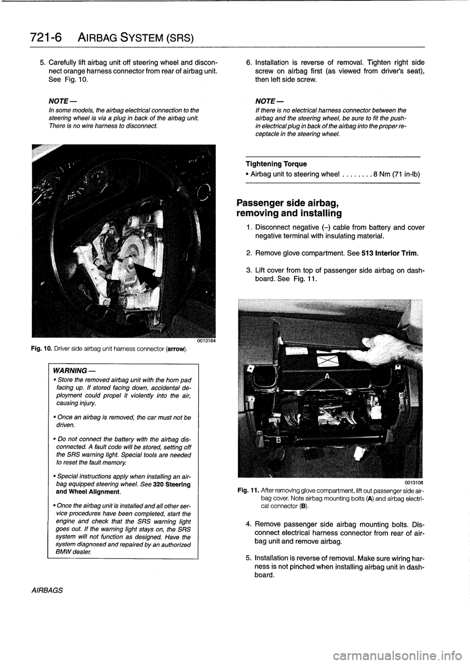
Fig
.
10
.
Driver
sideairbag
unit
harness
connector
(arrow)
.
AIRBAGS
WARNING
-
"
Store
the
removed
airbag
unit
with
the
horn
pad
facing
up
.
If
stored
facing
down,
accidental
de-
ployment
couldpropel
it
violently
into
the
air,
causing
injury
.
"
Once
an
airbag
is
removed,
the
car
must
not
be
driven
.
"
Do
not
connect
the
battery
with
the
airbag
dis-
connected
.
A
fault
code
will
be
stored,
setting
off
the
SRS
warning
light
.
Special
tools
are
needed
to
reset
the
fault
memory
.
"
Special
instructions
apply
when
installing
an
air-
bag
equipped
steering
wheel
.
See
320
Steering
and
Wheel
Alignment
.
"
Once
the
airbag
unit
is
installnd
and
all
other
ser-vice
procedureshave
been
completed,
start
the
engíne
and
check
that
the
SRS
warning
light
goes
out
.
If
the
warning
light
stays
on,
the
SRS
system
will
not
function
as
designed
.
Have
the
system
diagnosed
and
repaired
by
an
authorized
BMW
dealer
.
0013184
Tightening
Torque
"
Airbag
unitto
steering
wheel
........
8
Nm
(71
in-lb)
Passenger
side
airbag,
removing
and
installing
1
.
Disconnect
negative
(-)
cable
from
battery
and
cover
negative
terminal
with
insulating
material
.
2
.
Remove
glove
compartment
.
See
513
Interior
Trim
.
3
.
Lift
cover
from
topof
passenger
sideairbag
on
dash-
board
.
See
Fig
.
11
.
0013108
Fig
.
11
.
After
removing
glove
compartment,
lift
out
passenger
side
air-
bag
cover
.
Note
airbag
mounting
bolts
(A)
and
airbag
electri-
cal
connector
(B)
.
4
.
Remove
passenger
sideairbag
mounting
bolts
.
Dis-
connect
electrical
harness
connector
from
rear
of
air-
bag
unit
and
remove
airbag
.
5
.
Installation
is
reverse
of
removal
.
Make
sure
wiring
har-
ness
is
not
pínched
when
installing
airbag
unit
in
dash-board
.
Page 539 of 759
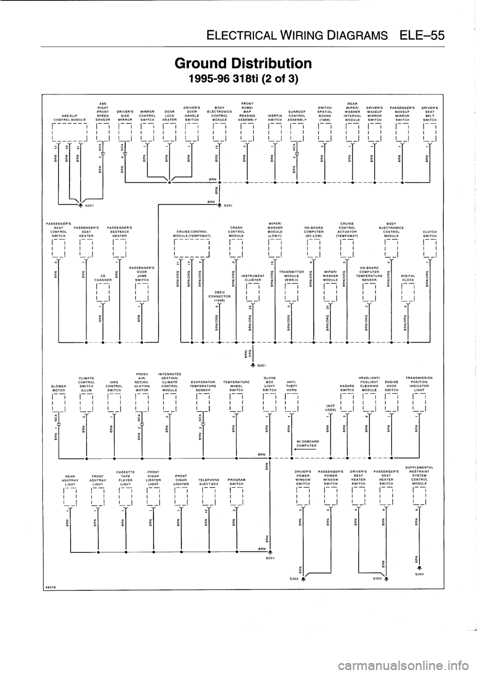
84318
ASS
FRONT
REAR
RIGHT
DRIVER'S
BODY
DOME/
SWITCH
WIPER/DRIVER'S
PASSENGER'S
DRIVER'S
FRONT
DRIVER'S
MIRROR
DOORDOOR
ELECTRONICS
MAP
SUNROOF
SPATIAL
WASHER
MAKEUP
MAKEUP
SEAT
ASSSLIP
SPEED
SIDE
CONTROL
LOCK
HANDLE
CONTROLREADING
INERTIA
CONTROL
SOUND
INTERVAL
MIRROR
MIRROR
BELTCO
.TPOLMOOULESENSOR
MIRRORSWITCHHEATER
SWITCH
MODULE
ASSEMBLY
SWITCH
ASSEMBLY
(1996)
MODULE
SWITCH
SWITCH
SWITCH
r
i
F-
,1
-
7
F
-
,
F-
,
F
-
,
F
-
,
F-
,
F-
,
F-
,
F-
,
F
-
,
F-
,I
i
I
i
I
I
I
I
I
I
I
I
I
I
I
I
I
I
I
I
,
,
I
I
I
I
,
I
I
I
I
I
I
v
I
J
!
._I
L-1
L-1
L-1
L-1
L-1
I
_I
L-1
L-1
L-1
L-1
L-1
J
/-
4L
PASSENGER'S
DOOR
CD
JAMB
CHANGER
m
I
SWITCH
v
I
IIIII
F-
,
F-
,
F-
,I
I
I
I
I
I
I
I
I
I
I
I
I
I
I
I
ELECTRICAL
WIRING
DIAGRAMS
ELE-55
Ground
Distribution
1995-96
318ti
(2of3)
BE
.
PASSENGER'S
WIPER/
CRUISE
BODY
SEAT
PASSENGER'S
PASSENGER'S
CRASH
WASHER
ON-BOARD
CONTROL
ELECTRONICS
CONTROL
SEAT
SEATBACK
CRUIBECONTROL
CONTROL
MODULE
COMPUTER
ACTUATOR
CONTROL
CLUTCH
SWITCH
HEATER
HEATER
I
MODULE
(TEMPOMAT)
MODULE
(LOW
11)
(BC-LOW)
(TEMPOMAT)
MODULE
SWITCH
I
i
I
i
I
i
I
F
i
I
i
I
i
I
i
F-
,
I
i
F-
L
I
I
I
I
I
I
I
I
I
I
I
I
I
I
I
I
I
I
I
II
_I
!
_I
!
_I
I
_____J
_I
!
_I
!
_I
L-1
L-1
!
_I
12
INCLUS
ERT
ZI
TR(
WS11)
0
1
MODULE
2I
T
MSENSORURE
2I
CLOCK
I
I~
I
I
mm
m
m~
I
I
M~
I
I
m~
I
I~
I
I
m~
I
I
I
_
I
I
I
-)
I
I
I
CONNECTOR
I
,
-
I
I
I
-
I
I
_I
I
I
_I
I
I
_I
(1996)
FRESH
INTEGRATED
CLIMATE
AIR/
HEATING/
GLOVE
HEADLIGHT/
TRANSMISSION
CONTROL
IRKS
RECIRC-
CLIMATE
EVAPORATORTEMPERATURE
BOX
ANTI-
FOGLIGHT
ENGINE
POSITION
BLOWER
SWITCH
CONTROL
ULATION
CONTROLTEMPERATUREWHEEL
LIGHTTHEFT
HAZARD
CLEANING
HOOD
INDICATOR
MOTOR
ILLUM
SWITCH
MOTOR
MODULE
SENSOR
SWITCHSWITCH
HORN
SWITCH
MODULE
SWITCH
LIGHT
I
1
I
1
I
1
I
i
I
i
I
1
I
1
I
i
I
i
I
-
i
I
-
i
I
i
I
1
I
I
I
I
I
I
I
I
I
I
I
I
I
I
I
I
I
I
I
I
I
I
I
I
I
I
I
!
I
!
iI
_I
!
I
INOT
!
_I
I
I
I
I
!
I
USED)
I
!
I
!
I
!
I
=1
-
Y
-Y
Y
=1
Y
=Y
Y
~r
Y
YY
-Y
BEN
SUPPLEMENTAL
CASSETTE
FRONT
DRIVER'S
PASSENGER'S
DRIVER'S
PASSENGER'S
RESTRAINT
REARFRONTTAPE
CIGAR
FRONT
POWERPOWER
SEATSEAT
SYSTEM
ASHTRAY
ASHTRAY
PLAYER
LIGHTER
CIGAR
TELEPHONE
PROGRAM
WINDOW
WINDOW
HEATERHEATER
CONTROL
LIGHT
LIGHT
LIGHTLIGHT
LIGHTER
EJECTBOX
SWITCH
SWITCH
SWITCHSWITCH
SWITCH
MODULE
BEN
-1
G201
7
G302
1
W/ONBOARDCOMPUTER
II
F
-,
I
I1
-
7
F-
1
I
I
I
I
I
I
I
I
I
_I
L
-I
L
-I
L
_I
L
I
1
G303
Page 542 of 759
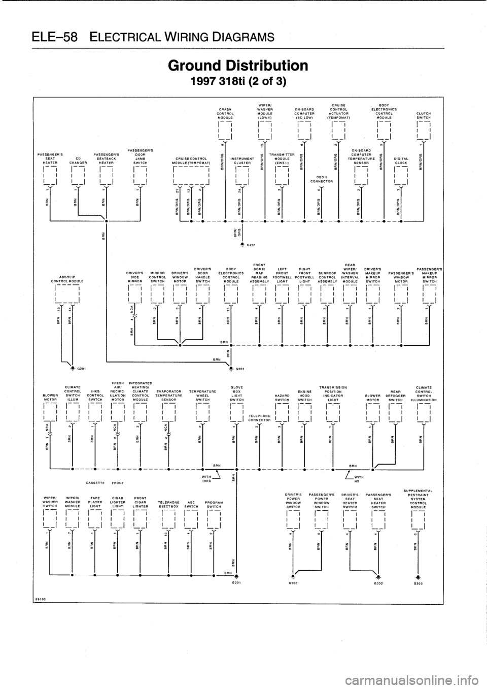
ELE-58
ELECTRICAL
WIRING
DIAGRAMS
1
8916
0
BRN
BRN
m
G201
>-
G201
I
I
I
I
I
I
,
I
I
I
,
I
I
I
_I
!
_I
I
I
!
_I
CASSETTE
FRONT
Ground
Distribution
1997
318ti
(2
of
3)
WIPER/
CRUISE
BODYCRASH
WASHER
ON-BOARD
CONTROL
ELECTRONICS
CONTROLMODULECOMPUTER
ACTUATOR
CONTROL
CLUTCHMODULE
LOW
I])
(BC-LOW)
ITEMPOMAT)
MODULE
SWITCH
I
I
I
I
I
I
I
I
I
I
(
II
I
I
I
I
I
I
I
I
I
I
I
_I
L_IL_IL_IL_I
L_I
PASSENGER'S
ON-BOARD
PASSENGER'S
PASSENGER'S
DOOR
(7
°
TRANSMITTER
°
OCOMPUTER°
SEAT
CD
SEATBgCK
JAMB
CRUISE
CONTROL
INSTRUMENT
MODULE
TEMPERATURE
DIGITAL
HEATER
CHANGER
HEATER
SWITCH
MODULE
(TEMPOMAT)
~
CLUSTER
~
(EWSII)
~
~
SENSOR
~
CLOCK
I
I
I
I
I
I
I
I
I
I
I
I
I
I
DBDII
I
I
I
I
_I
!
_I
!
_I
!
_I
!
_____J
I
_I
I
_I
CONNECTOR
,
-
I
,
-1
FRONT
REAR
DRIVER'S
BODY
DOME/
LEFT
RIGHT
WIPER/DRIVER'S
PASSENGER'S
DRIVER'S
MIRROR
DRIVER'S
DOOR
ELECTRONICS
MAP
FRONTFRONT
SUNROOF
WASHER
MAKEUP
PASSENGER'S
MAKEUP
ABSSIIP
SIDE
CONTROL
WINDOW
HANDLE
CONTROL
READING
FOOTWELL
FOOTWELL
CONTROL
INTERVAL
MIRROR
WINDOW
MIRROR
CONTROL
MODULE
MIRROR
SWITCH
MOTOR
SWITCH
MODULE
ASSEMBLY
LIGHT
LIGHT
ASSEMBLY
MODULE
SWITCH
MOTOR
SWITCH
I
i
F-
,
I
i
F
-
,
F-
,
F
-
,
I
i
I
i
I
i
I
i
I
i
I
-
i
I
i
I
-
i
I
I
I
I
I
I
I
I
I
I
I
I
I
I
I
I
I
I
I
I
I
I
I
I
I
1
I
I
I
---I
I
~
_I
L
-I
L-1
L-1
L-1
L-1
L-1
L-1
L-1
!
_I
L-1
L-1
L-1
rr
r
rr
r
r
r
Y
r
v
.
.
~
.
FRESH
INTEGRATED
CLIMATE
AIRI
HEATING/
GLOVE
TRANSMISSION
CLIMATE
CONTROL
INKS
RECIRC-
CLIMATE
EVAPORATOR
TEMPERATURE
BOX
ENGINE
POSITION
PEARCONTROLBLOWER
SWITCH
CONTROL
ULATION
CONTROL
TEMPERATURE
WHEEL
LIGHT
HAZARD
H000
INDICATOR
BLOWERDEFOGGER
SWITCH
MOTOR
ILLUM
SWITCH
MOTORMODULESENSOR
SWITCHSWITCH
SWITCHSWITCH
LIGHT
MOTOR
SWITCH
ILLUMINATION
F-
1
F-
1
F-
1
1
--
i
F-
1
F
-
,
F-
I
F
-
1
F-
1
1
-
1
F
-
1
I
-
i
I
i
(-
i
I
I
,
I
I
I
I
I
,
I
I
I
I
I
TELEPHONE
CONNECTOR
I
I
I
_I
!
_I
YY
Y
Y
.
.Y
Y
Y
Y
BEN
1
I
I
I
1
eRN
WITH
WITH
IHKSHS
SUPPLEMENTAL
DRIVER'S
PASSENGER'S
DRIVER'S
PASSENGER'S
RESTRAINT
WIPER/WIPER/
TAPE
CIGAR
FRONT
POWERPOWER
SEATSEAT
SYSTEM
WASHERWASHER
PLAYER
LIGHTER
CIGAR
TELEPHONE
ABC
PROGRAM
I
WINDOWWINDOW
HEATERNEATER
CONTROL
SWITCH
MODULE
LIGHT
LIGHT
LIGHTER
EJECT
BOX
SWITCH
SWITCH
SWITCH
SWITCH
SWITCH
SWITCH
MODULE
I
v
I
i
1
-
7
1
i
I
i
1
i
I
i
I
-
(-
i
1
-
7
I
I
I
I
I
I
,
I
I
I
I
I
I
I
,
I
I
I
I
I
I
I
I
I
-r
lY_Y
Y
_Y
Y
Y
Y
A
-
G302
G302
.303