Hood BMW 318i 1997 E36 Owner's Manual
[x] Cancel search | Manufacturer: BMW, Model Year: 1997, Model line: 318i, Model: BMW 318i 1997 E36Pages: 759
Page 419 of 759
611
Wipers
and
Washers
GENERAL
..
.
.
.
.
.
.
.
.
.
.
.
.
.
.....
.
......
.
611-1
Windshield
wiper
motor,
removing
and
installing
.
...............
.611-8
WIPER
BLADES
.
.
.
.....
.
.
.
.
.
.
...
....
.611-1
Wiper
Blade
Cleaning
Problems
.
.
.
.
.
.
.....
611-1
Wiper
blades,replacing
...
.
.
.
.
.
.
.
.
.
.....
611-1
Wiper
blade
inserts,
replacing
.
.
.
.
.
.
.
.
.....
611-2
Wiper
arms,
removing
and
installing
.
.
.
.....
611-2
WINDSHIELD
WIPER
ASSEMBLY
.
.
.....
611-3
Windshield
wiper
assembly,
removing
and
installing
(4-door
models)
.
.
.
.
.
.
.....
611-3
Windshield
wiper
assembly,
removing
and
installing
(2-door
models)
.
.
.
.
.
.
.....
611-5
GENERAL
This
repair
group
covers
windshield
wiper
and
washer
sys-
tem
repair
information
.
Please
note
that
some
procedures
are
different
for
2-
and
4-door
models
.
The
windshield
wiper/washer
stalk
switch
assembly
is
cov-
ered
in
612
Switches
and
Electrical
Accessories
.
Electrical
NOTE-
wiring
diagrams
and
relays
for
the
wiper/washer
system
are
BMwhas
available
a
special
toollgauge
(BMWspecial
covered
in
Electrical
Wiring
Diagrams
.
tool
no
.
00
9210)
to
align
the
angle
of
the
wiper
arm
to
the
windshield
glass
.
WIPERBLADES
CA
UTION-
Never
turn
on
the
wiper
blades
while
the
hood
is
open
.
Damage
to
the
wiper
system
and
hood
may
occur
.
Toensure
safetyduring
wiper
biade
system
procedures,
remove
the
windshieldwiper
fuse
.
See
610
Electrical
Component
Locations
.
Wiper
Blade
Cleaning
Problems
Common
cleaning
problems
with
thewipers
includestreak-
ing
or
sheeting,
waterdrops
after
wiping,
and
blade
chatter
.
Streaking
is
usually
caused
when
wiper
blades
are
coated
with
road
film
or
car
wash
wax
.
Clean
the
blades
using
soapy
water
.
If
cleaning
does
not
cure
the
problem,
the
blades
should
be
replaced
.
BMW
recommends
replacing
the
wiper
blades
twice
a
year,
before
and
after
the
cold
season
.
WIPERS
AND
WASHERS
611-1
WINDSHIELD
CLEANING
SYSTEM
......
611-9
Windshield
spray
nozzle,
removing
and
installing
.......
.
........
.611-9
Washer
fluid
reservoir,
replacing
.........
.611-9
Windshield
washer
fluid
pump,
replacing
..
.
......
.
........
.611-9
Washer
fluid
level
sensor,
replacing
(models
with
check
control)
.
.
.
.
........
611-10
Wiper
blade
chatter
may
be
caused
by
dirty
or
worn
blades,
or
by
wiper
arms
that
areout
of
alignment
.
Clean
the
blades
and
windshield
as
described
above
.
Adjust
the
wiper
arm
so
that
there
is
even
pressure
along
the
blade,
and
so
that
the
blade
at
rest
is
perpendicular
to
the
windshield
.
If
problems
persist,
theblades
and
wiper
arms
should
be
replaced
.
The
wiper
blades
can
be
renewed
in
one
of
two
ways
:
either
by
replacing
the
complete
blade
or
by
replacing
just
therubber
insert
.
Insert
replacement
is
the
mosteconomicalmethod,
al-
though
overtime
the
wiperblade
itselfwill
become
worn
.
One
ruleof
thumb
wouldbe
to
replace
just
the
inserts
every
second
time
.
Wiper
blades,
replacing
1
.
Pivot
wiper
arm
off
windshield
.
2
.
Position
wiperblade
approximately
perpendicular
to
wiper
arm
.
3
.
Remove
wiperblade
from
wiper
arm
by
depressing
re-
taining
tab
and
sliding
blade
out
of
arm
.
See
Fig
.
1
.
Drops
that
remain
behind
after
wiping
are
usually
caused
by
NOTE-
oil,
road
film,
or
diesel
exhaust
residue
onthe
glass
.
Use
an
Some
wiperblade
versions
may
havetwo
retaining
alcohol
or
ammonia
solution
or
a
non-abrasive
cleaner
(such
tabs
.
a
s
Bon-Ami
to
clean
the
windshield
.
GENERAL
Page 420 of 759
611-2
WIPERS
AND
WASHERS
5
.
Slide
new
insert
through
wiperblade
guides
.
Lock
in-
sert
m
place
at
end
gudes
.
.,
\
-
-
--
,
1
Wiper
arms,
removing
and
installing
Fig
.
1
.
Windshield
wiper
biade
retaining
tab
.
Press
in
on
tab
(arrow)
to
release
bfade
from
arm
.
4
.
Installation
is
reverse
of
removal
.
Instan
wiperblade
to
wiper
arm
until
retaining
tab
can
be
heard
toclickinto
position
.
Wiper
biade
inserts,
replacing
1
.
Remove
wiper
blade
as
described
earlier
.
2
.
Unhook
end
of
wiper
blade
insert
fromwiper
arm
guides
.
See
Fig
.
2
.
0011784
Fig
.
2
.
Unhook
wiperbiade
insert
from
wiper
arm
guide
.
If
necessary,
guide
slightly
usingneed1e
nose
pliers
.
3
.
Pull
old
insert
fromwiper
arm
guides,
noting
installation
position
.
4
.
Remove
metal
support
strips
from
old
insert
and
instan
intoslots
in
new
insert,
noting
installation
direction
of
cutouts
in
support
strips
.
GENERAL
NOTE
-
The
notched
cutouts
in
the
retaining
strips
should
en-
gage
the
molded
notches
in
the
inserts
.
NOTE-
On
2-door
models
it
may
be
necessary
to
raise
the
hood
to
the
service
position
.
See
410
Fenders,
Engine
Hood
.
CAUTION-
"
Use
fender
cover
to
protect
windshield
.
"
Remove
windshield
wiper
fuse
to
prevent
acci-
dents
.
1.
With
engine
hood
in
closed
position,
remove
both
wiper
blades
.
2
.
Open
hood
.
Remove
cap
covering
wiper
arm
retaining
nutsby
inserting
anarrow
screwdriver
biade
in
slot
be-
low
capand
prying
upward
.
NOTE
-
Marking
position
of
wiper
arm
on
shaft
will
aid
installa-tion
.
3
.
Using
a13
mm
socket,
remove
wiper
arm
retaining
nut
andremove
wiper
arm
.
See
Fig
.
3
.
Fig
.
3
.
Wiper
arm
retaining
nut
.
(arrow)
.
,
NOTE
-
ft
may
benecessary
to
gently
rock
wiper
arm
back
and
forth
to
loosen
arm
from
shaft
.
Page 422 of 759
611-
4
WIPERS
AND
WASHERS
2
.
Remove
wiper
arms
as
described
earlier
.
3
.
Place
engine
hood
in
service
position
.
See
410
Fend-
ers,
Engine
Hood
.
4
.
Unclip
engine
bulkhead
plenum
grille
at
base
of
wind-
shield
and
pulí
it
away
from
rubbergasket
.
See
Fig
.
5
.
Fig
.
5
.
Detach
grill
clips
(arrows)
and
pull
upward
.
0012527
5
.
Remove
wiring
harness
retaining
clip
frombulkhead
in
rear
of
engine
bay
.
Remove
screws
retaining
wiring
harness
protective
cover
.
See
Fig
.
6
.
0012529
Fig
.
6
.
Engine
bulkhead
wiring
harness
cover
screws
(arrows)
.
WINDSHIELD
WIPER
ASSEMBLY
Fig
.
7
.
Right
side
plenum
retaining
screws
(arrows)
.
7
.
On
driver's
side
of
air
plenum,
push
aside
wiring
har-
ness
and
remove
screw
retaining
plenum
.
Pull
plenum
up
andremove
from
engine
compartment
.
See
Fig
.
8
.
001¿534
Fig
.
8
.
Remove
screw
at
A
and
pull
plenum
housing
upward
.
8
.
On
6-cylinder
models
:
Remove
plastic
top
engine
cov-
ers
.
See
110Engine
Removal
and
Installation
.
NOTE-
Cover
ínside
edges
of
cowlpanelsheet
metal
with
thick
tape
to
prevent
damage
during
wiper
assembly
remov-
al
.
9
.
Remove
large
nut
and
washer
at
base
of
wiper
arm
shafts
cowi
panel
.
See
Fig
.
9
.
10
.
Remove
wiper
assembly
support
.
See
Fig
.
10
.
6
.
On
passenger
side
of
air
plenum,
push
aside
wiring
11
.
Separateharness
at
bulkhead
connector
.
See
Fig
.
11
.
harness
and
remove
twoscrews
retaining
plenum
housing
.
See
Fig
.
7
.
12
.
Wrap
protective
tape
around
wiper
shaft
on
driver's
side
to
prevent
damaging
painted
metal
during
remov-
al
.
Page 423 of 759
Fig
.
9
.
Wiper
shaft
nut
at
cowl
(arrow)
.
Fig
.
10
.
Wiper
assembly
support
bolts
(arrows)
.
0012533
0012535
Fig
.
11
.
Wiper
assembly
electrical
connector
(arrow)
.
0012536
13
.
Push
wiper
arm
shaft
down
into
cowl
area
and
maneu-
ver
wiper
assembly
out
of
cowl
.
WIPERS
AND
WASHERS
611-
5
14
.
Installation
is
reverse
of
removal,noting
the
following
:
"
Install
all
fasteners
finger-tight
first
.
"
Once
installed,
wiper
motor
should
first
be
run
to
parked
position
and
switched
off
.
"
Next,
instaf
wiper
arms
butnotblades
.
"
Close
hood
and
fit
wiper
blades
.
"
Check
all
electrical
harness
fittings
and
sealing
grom-
mets
for
correct
reinstallation
.
Replace
any
wire
ties
cut
off
during
removal
.
Tightening
Torques
"
Wiper
shaft
nut
at
cowl
.............
12
Nm
(9
ft-Ib)
"
Wiper
support
to
wiper
assembly
orto
body
..
..
..
.
...............
10
Nm
(89
in-lb)
"
Wiper
arm
to
wiper
shaft
..........
25
Nm
(18
ft-lb)
Windshieldwiper
assembly,
removing
and
installing
(2-door
modeis)
NOTE-
The
wiper
arms
should
be
in
the
parked
position
before
removing
the
wiper
assembly
.
To
avoid
damaging
the
wiper
arms
and
pivots,
donotmanually
sidde
or
force
the
wiper
arm
across
the
windshield
.
1
.
Disconnect
negative
(-)cablefrom
battery
.
CAUTION-
"
Prior
to
disconnectiog
the
battery,
read
the
bat-
tery
disconnection
cautionsgiven
at
the
front
of
this
manual
on
page
viii
.
"
Use
fendercover
to
protect
windshield
.
2
.
Remove
wiper
arms
as
described
earlier
.
3
.
Place
engine
hood
in
service
position
.
See410
Fend-
ers,
Engine
Hood
.
4
.
Remove
trim
retainers
at
left
and
right
side
and
remove
air
plenum
grill
.
See
Fig
.
12
.
5
.
Remove
screws
retaining
wiring
harness
protective
cover
.
See
Fig
.
13
.
6
.
On
passenger
side
of
air
plenum,push
aside
wiring
harness
and
remove
two
screws
retaining
plenum
housing
.
See
Fig
.
14
.
WINDSHIELD
WIPER
ASSEMBLY
Page 425 of 759
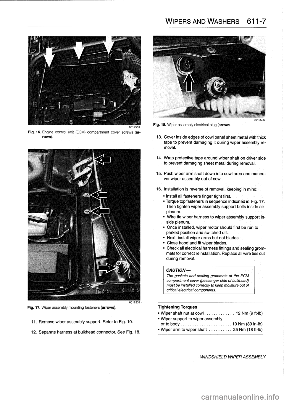
0012531Fig
.
16
.
Engine
control
unit
(ECM)
compartment
cover
screws
(ar-
rows)
.
WIPERS
AND
WASHERS
611-
7
Fig
.
18
.
Wiper
assembly
electrical
plug
(arrow)
.
uu1zbs6
13
.
Cover
inside
edges
of
cowi
panelsheet
metal
with
thick
tape
to
prevent
damaging
it
during
wiper
assembly
re-
moval
.
14
.
Wrap
protective
tape
around
wiper
shaft
on
driver
side
to
prevent
damaging
sheet
metal
during
removal
.
15
.
Push
wiper
arm
shaft
down
into
cowiarea
and
maneu-
ver
wiper
assembly
outof
cowi
.
16
.
Installation
is
reverse
of
removal,
keeping
in
mind
:
"
Install
all
fasteners
finger
tight
first
.
"
Torque
topfasteners
in
sequence
indicated
in
Fig
.
17
.
Then
tighten
wiper
assembly
support
bolts
inside
air
plenum
.
"
Wire
tie
wiper
harness
lo
wiper
assembly
support
in-
side
plenum
.
"
Once
installed
;
wiper
motor
should
first
be
run
to
parked
position
and
switched
off
.
"
Next,
insta¡¡
wiper
arms
butnot
blades
.
"
Close
hood
and
fit
wiper
blades
:
"
Check
all
electrical
harness
fittings
and
sealing
grom-
mets
for
correct
reinstallation
.
Replace
al]
wire
ties
cut
during
removal
.
CAUTION-
The
gaskets
and
sealing
grommets
at
the
ECM
compartment
cover
(passenger
sideof
bulkhead)
must
be
installed
correctly
to
keep
moisture
out
of
critica¡
electrical
componente
.
Fig
.
17
.
Wiper
assembly
mounting
fasteners
(arrows)
.
Tightening
Torques
"
Wiper
shaft
nut
at
cowi
..
.
.
..
.......
12
Nm
(9
ft-Ib)
11
.
Remove
wiper
assembly
support
.
Refer
to
Fig
.
10
.
"
Wiper
support
to
wiper
assembly
or
to
body
.........
...
..........
10
Nm
(89
in-lb)
12
.
Separate
harness
at
bulkhead
connector
.
See
Fig
.
18
.
-
Wiper
arm
to
wiper
shaft
..........
25
Nm
(18
ft-Ib)
WINDSHIELD
WIPER
ASSEMBLY
Page 427 of 759
WINDSHIELD
CLEANING
SYSTEM
Washer
f
luid
reservoir,
replacing
1
.
Open
hood
and
siphon
out
washer
fluid
reservoir
.
The
windshieldcleaning
system
includes
the
spray
nozzles
in
the
engine
hood,
the
washer
fluid
pump,
and
the
washer
flu-
id
reservoir
in
the
front
passenger
side
of
the
engine
compart-
ment
.
The
windshield
spray
nozzles
can
be
aimed
by
using
asew-
ing
need1e
or
a
similar
diameter
stiff
piece
of
wire
.
Windshield
spray
nozzle,
removing
and
installing
1
.
Open
hood
andremove
hood
insulating
pad
retaining
clips
until
bottom
of
nozzle
canbe
fully
accessed
.
See
410
Fenders,
Engine
Hood
.
2
.
Carefully
disconnect
hose
from
nozzle
.
Disconnect
har-
ness
connectors
for
nozzleheater
.
3
.
Push
nozzleout
of
hood
.
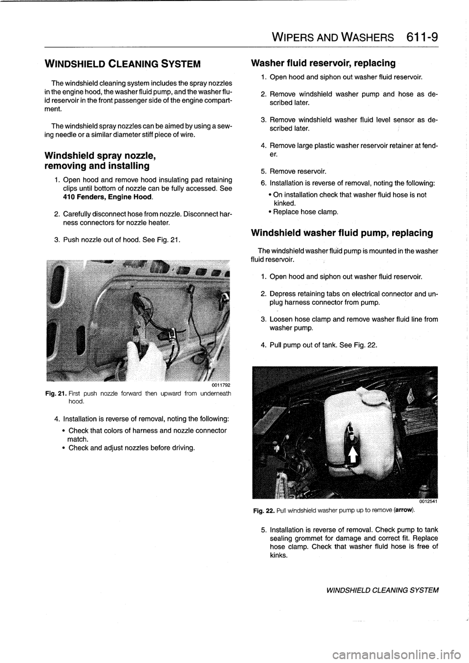
See
Fig
.
21
.
Fig
.
21
.
First
push
nozzle
forward
then
upward
from
underneath
hood
.
4
.
Installation
is
reverse
of
removal,
noting
the
following
:
"
Check
that
colors
of
harness
and
nozzle
connector
match
.
"
Check
and
adjust
nozzles
before
driving
.
WIPERSAND
WASHERS
611-
9
2
.
Remove
windshield
washer
pump
and
hose
as
de-
scribed
later
.
3
.
Remove
windshield
washer
fluid
level
sensor
as
de-
scribed
later
.
4
.
Remove
large
plastic
washer
reservoir
retainer
at
fend-
e
r
.
5
.
Remove
reservoir
.
6
.
Installation
is
reverse
of
removal,
noting
the
following
:
"
On
installation
check
that
washer
fluid
hose
is
not
kinked
.
"
Replacehose
clamp
.
Windshield
washer
fluid
pump,
replacing
The
windshield
washer
fluid
pump
ís
mounted
in
the
washer
fluid
reservoir
.
1
.
Open
hood
and
siphon
out
washer
fluid
reservoir
.
2
.
Depress
retaining
tabs
on
electrical
connector
and
un-
plug
harness
connector
from
pump
.
3
.
Loosen
hose
clamp
and
remove
washer
fluidline
from
washer
pump
.
4
.
PA
pump
out
of
tank
.
See
Fig
.
22
.
Fig
.
22
.
Pull
windshield
washer
pump
up
to
remove
(arrow)
.
5
.
Installation
is
reverse
of
removal
.
Check
pump
to
tank
sealing
grommet
for
damage
and
correct
fit
.
Replace
hose
clamp
.
Check
that
washer
fluid
hose
is
free
of
kinks
.
WINDSHIELD
CLEANING
SYSTEM
Page 428 of 759
611-
1
0
WIPERS
AND
WASHERS
Washer
fluidleve¡
sensor,
replacing
(modeis
with
check
control)
The
washer
fluid
level
sensor
is
mounted
in
the
fluid
reser-
voir,
near
the
bottom
of
thecontainer
.
NOTE-
Check
wire
leads
at
sensor
for
worn
insulation
and
cor-
rosion
.
Check
electrical
contacts
in
harness
connector
for
corrosion
.
1
.
Open
hood
and
siphon
out
washer
fluid
reservoir
.
2
.
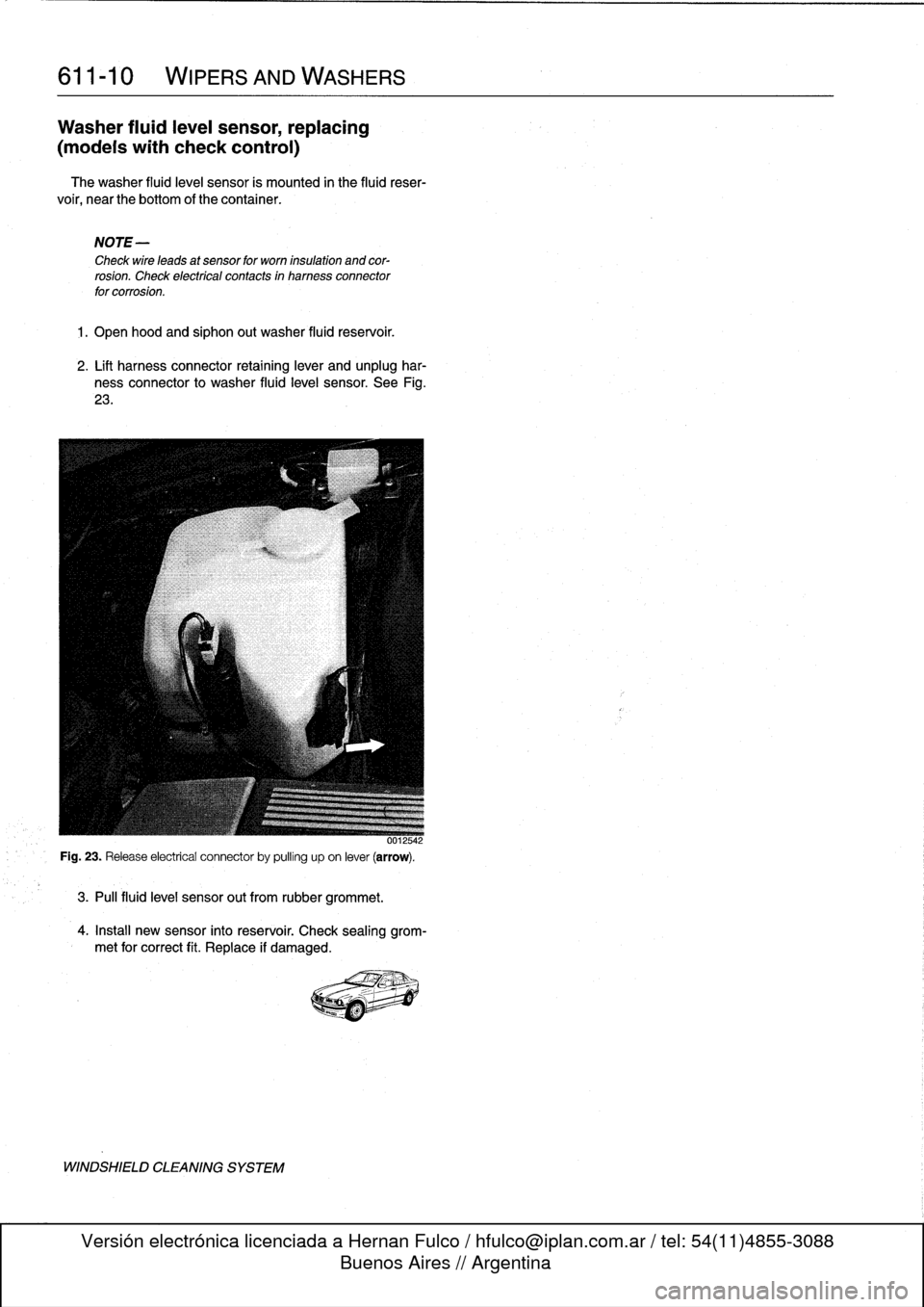
Lift
harness
connector
retaining
lever
and
unplug
har-
ness
connector
to
washer
fluid
level
sensor
.
See
Fig
.
23
.
3
.
Pul¡
fluid
leve¡
sensor
out
from
rubber
grommet
.
4
.
Install
new
sensor
into
reservoir
.
Check
sealing
grom-
met
for
correct
fit
.
Replace
if
damaged
.
WINDSHIELD
CLEANING
SYSTEM
Page 441 of 759
FRONT
LIGHTING
.
...........
.
....
.
.
.
.
630-1
Headlight
buib,
replacing
............
.
.
.
.
630-1
Headlight
assembly,
removing
and
installing
.......
.
....
.
.
.
.
630-2
Foglight
assembly,
removing
and
installing
..
630-3
Front
turn
signal
assembly,
removing
and
installing
.....
.
.
.
........
630-4
GENERAL
The
headlight
and
foglight
assemblies
usehalogen
bulbs
.
To
ensure
the
longevity
of
halogen
bulbs,
the
bulb
glass
should
not
be
handied
.
Dirt
and
skin
oíls
may
cause
a
bulbto
fail
prematurely
.
If
necessarywipe
bulb
using
a
clean
cloth
dampened
with
rubbing
alcohol
.
NOTE-
Use
only
original
equipment
replacement
bulbs
.
Non-
original
equipment
bulbs
may
cause
false
failure
read-
ings
on
the
check
control
display
(where
applicable)
.
WARNING
-
INhenworking
on
electrical
systems,
remove
the
fuse
protecting
the
circuit
under
repair
.
See
610
Electrical
Component
Locations
.
FRONT
LIGHTING
Headlight
bulb,
replacing
1
.
Open
engine
hood
.
2
.
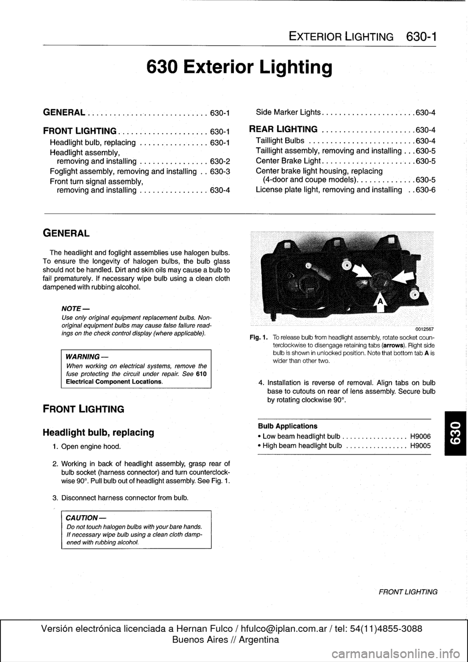
Working
in
back
of
headlight
assembly,grasp
rear
of
bulbsocket
(harnessconnector)
and
turn
counterclock-
wise
90°
.
Pull
bulb
out
of
headlight
assembly
.
See
Fig
.
1
.
3
.
Disconnect
harness
connector
from
bulb
.
CA
UTION-
Do
not
touch
halogen
bubs
with
yourbare
hands
.
If
necessary
wipe
bulb
using
a
clean
cloth
damp-
ened
with
rubbing
alcohol
.
630
Exterior
Lighting
EXTERIOR
LIGHTING
630-1
GENERAL
.
.
.
.
...
.
................
.
.
.
.
630-1
Side
Marker
Lights
.......
.
.
.
.
.
.......
.
..
630-4
REAR
LIGHTING
.
......
.
.
.
.
.
.
.
...
.
.
.
..
630-4
Taillight
Bulbs
..........
.
.
.
.
.
.....
.
.
.
.
.
630-4
Taillight
assembly,
removing
and
installing
.
.
.
630-5
CenterBrake
Light
.......
.
.
.
.
.
.
.
.
.
.
.
.
.
.
.
630-5
Center
brake
light
housing,
replacing
(4-door
and
coupe
models)
.
.
.
.
.......
.
.
.630-5
License
plate
light,
removingand
installing
.
.630-6
0012567
Fig
.1.
Torelease
bulbfrom
headlight
assembly,
rotate
socket
coun-
terclockwise
to
disengage
retaining
tabs
(arrows)
.
Right
side
bulb
is
shown
in
unlocked
position
.
Note
that
bottom
tab
A
is
wider
than
other
two
.
4
.
Installation
is
reverse
of
removal
.
Align
tabs
on
bulb
base
to
cutouts
on
rear
of
lens
assembly
.
Secure
bulb
by
rotating
clockwise
90°
.
Bulb
Applications
"
Low
beam
headlight
bulb
...
.
..
..
.........
H9006
"
High
beam
headlight
bulb
..
.
..
..
.........
H9005
FRONT
LIGHTING
Page 442 of 759
630-2
EXTERIOR
LIGHTING
Headlight
assembly,
removing
and
installing
CAUTION-
Followingheadlight
assembly
work
headlight
beam
aim
must
be
adjusted
using
special
equip-
ment
.
1
.
Left
side
:
Remove
air
filter
housing,
air
intake
duct,
and
air
mass
meter
.
See
100
Engine-General
.
2
.
Disconnect
harness
connectors
from
headlight
bulbs
.
3
.
Remove
front
turn
signal
.
See
Front
turn
signal
as-
sembly,
removingand
installing
later
in
this
repair
group
.
4
.
Remove
radiator
cover
.
See
Fig
.
2
.
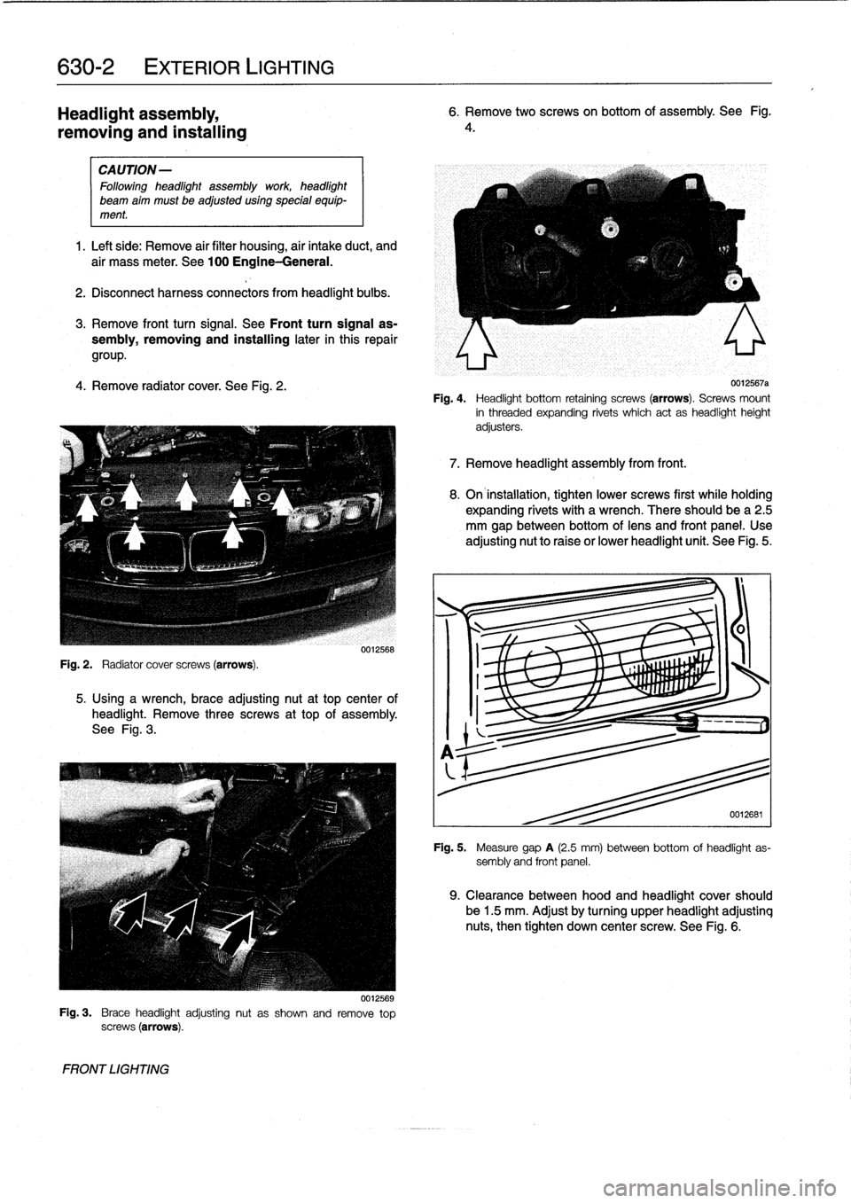
5
.
Using
a
wrench,
brace
adjusting
nut
at
top
center
of
headlight
.
Remove
three
screws
at
top
of
assembly
.
See
Fig
.
3
.
Fig
.
3
.
Brace
headlightadjustingnut
as
shown
and
remove
top
screws
(arrows)
.
FRONT
LIGHTING
0012568
0012569
6
.
Remove
two
screwson
bottom
of
assembly
.
See
Fig
.
4
.
0012567a
Fig
.
4
.
Headlight
bottom
retaining
screws
(arrows)
.
Screws
mount
in
threaded
expanding
rivets
which
act
as
headlightheight
adjusters
.
7
.
Remove
headlight
assembly
from
front
.
8
.
On
installation,
tighten
lower
screws
first
while
holding
expanding
rivets
with
a
wrench
.
There
should
be
a
2
.5
mm
gap
between
bottom
oflens
and
front
panel
.
Use
adjusting
nut
to
raise
or
lower
headlight
unit
.
See
Fig
.
5
.
0012681
Fig
.
5
.
Measure
gap
A
(2.5
mm)
between
bottom
of
headlight
as-
sembly
and
front
panel
.
9
.
Clearance
between
hood
and
headlight
cover
should
be
1
.5
mm
.
Adjust
by
turning
upper
headlight
adjustinq
nuts,
then
tighten
down
center
screw
.
See
Fig
.
6
.
Page 443 of 759
4
Foglight
assembly,
removing
and
installing
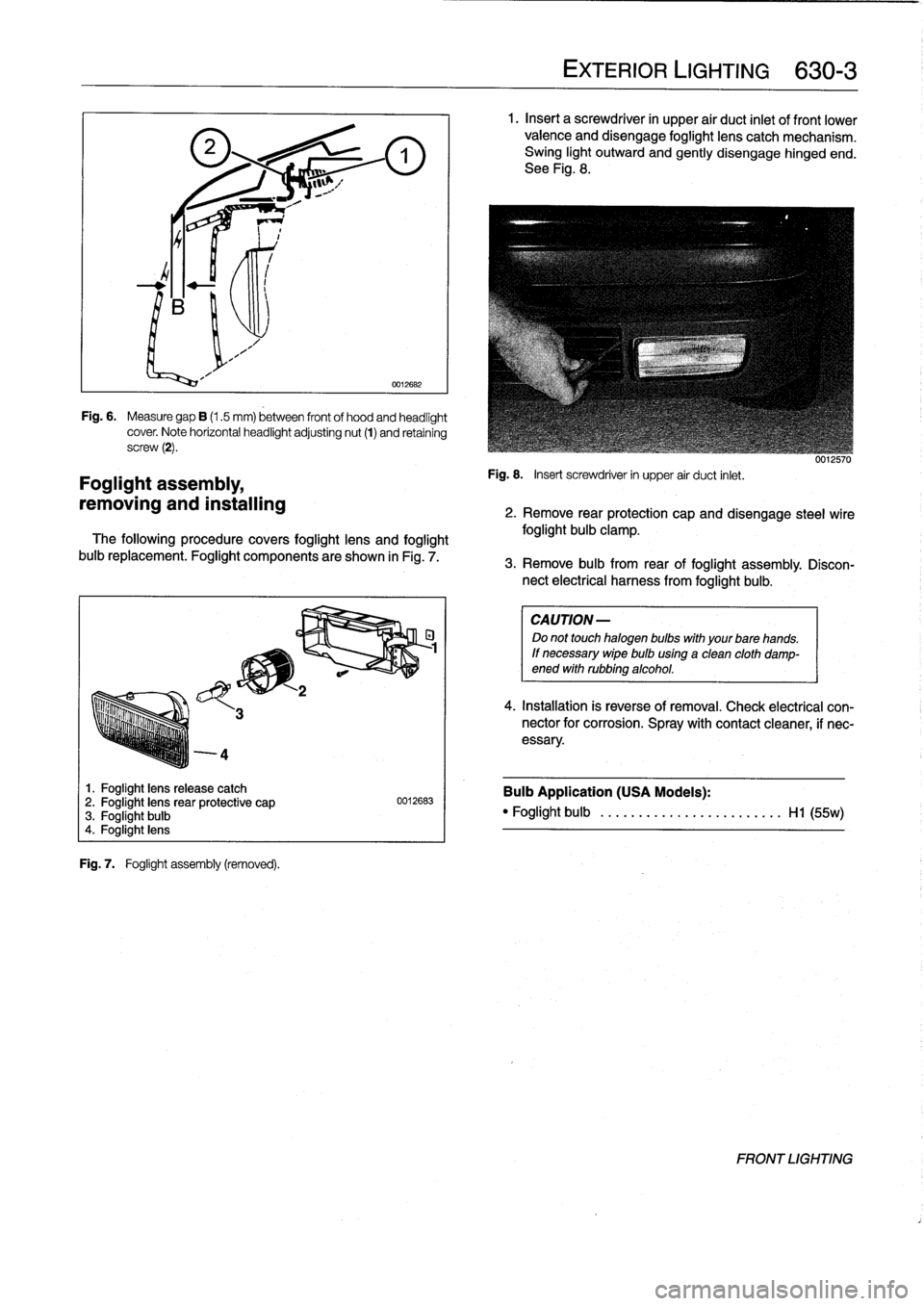
1
.
Foglight
lens
release
catch
2
.
Foglight
lensrear
protective
cap
3
.
Foglight
bulb
4
.
Foglight
lens
Fig
.
7
.
Foglight
assembly
(removed)
.
0012682
Fig
.
6
.
Measure
gap
B
(1.5
mm)
between
front
of
hood
and
headlight
cover
.
Note
horizontal
headlightadjusting
nut
(1)
and
retaining
screw
(2)
.
The
following
procedure
covers
foglight
lens
and
foglight
buib
replacement
.
Foglight
components
are
shown
in
Fig
.
7
.
0012683
EXTERIOR
LIGHTING
630-
3
1
.
Insert
a
screwdriver
in
upper
air
duct
inlet
of
front
lower
valence
and
disengage
foglight
lens
catch
mechanism
.
Swing
light
outward
and
gently
disengage
hinged
end
.
See
Fig
.
8
.
Fig
.
8
.
Insert
screwdriver
in
upper
air
duct
inlet
.
uu¡¿biu
2
.
Remove
rear
protection
capand
disengage
steel
wire
foglight
bulb
clamp
.
3
.
Remove
bulb
from
rear
of
foglight
assembly
.
Discon-
nect
electrical
harness
from
foglight
bulb
.
CAUTION
-
Do
not
touch
halogen
bulbs
with
yourbare
hands
.
If
necessary
wipe
buib
using
a
clean
cloth
damp-ened
withrubbing
alcohol
.
4
.
Installation
is
reverse
of
removal
.
Check
electrical
con-nector
for
corrosion
.
Spray
with
contact
cleaner,
if
nec-
essary
.
Bulb
Application
(USA
Models)
:
"
Foglight
bulb
......
...
..
...
..........
Hl
(55w)
FRONT
LIGHTING