seat BMW 325i 1993 E36 Workshop Manual
[x] Cancel search | Manufacturer: BMW, Model Year: 1993, Model line: 325i, Model: BMW 325i 1993 E36Pages: 759
Page 3 of 759
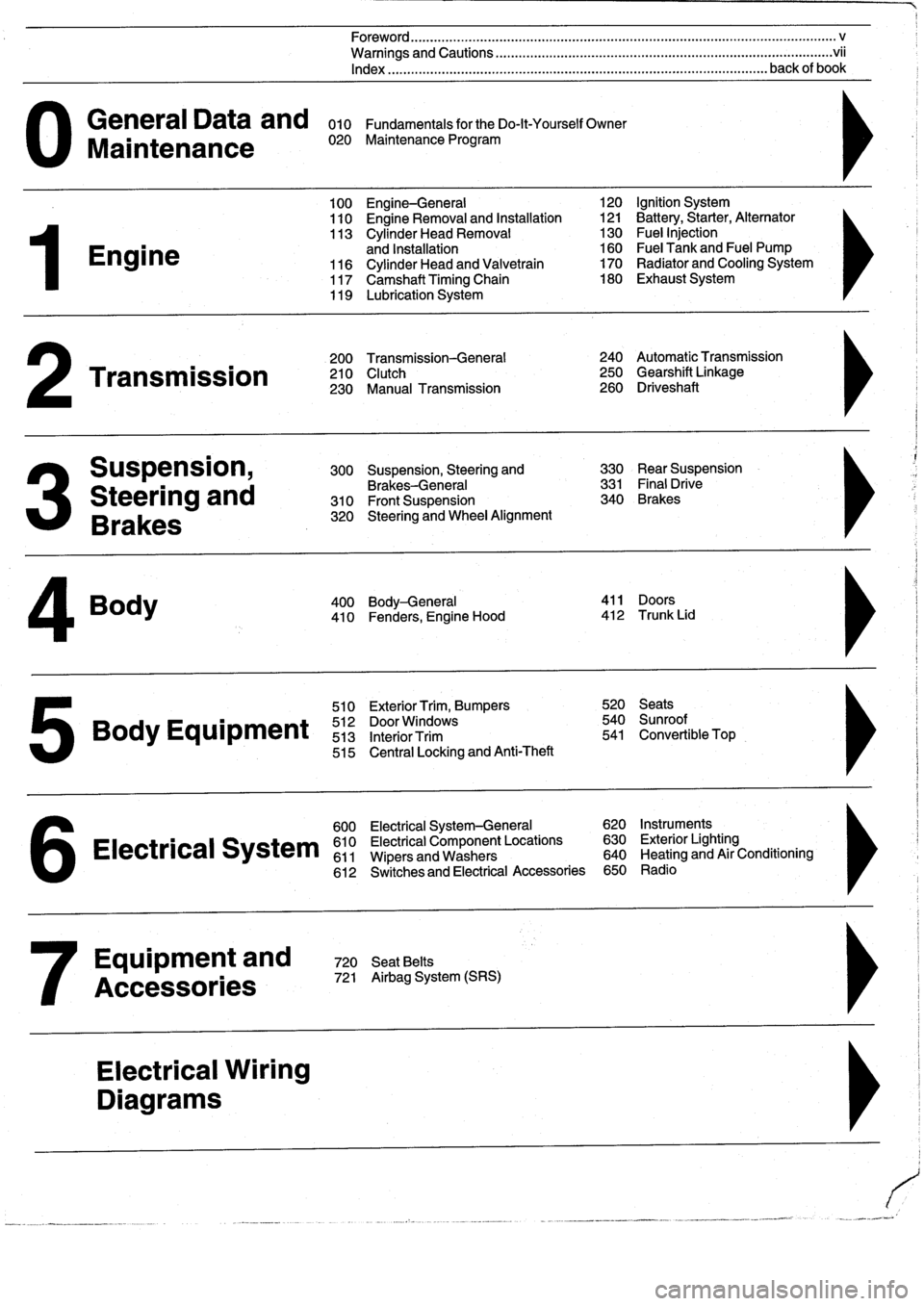
General
Data
and
010
FundamentalsfortheDo-lt-YourselfOwner
Maintenance
020
Maintenance
Program
Engine
Transmission
Suspension,
Steering
and
Brakes
4
Body
100
Engine-General
110
Engine
Removal
and
Installation
113
Cylinder
Head
Removal
and
Installation
116
Cylinder
Head
and
Valvetrain
117
Camshaft
Timing
Chain
119
Lubrication
System
200
Transmission-General
210
Clutch
230
Manual
Transmission
510
Exterior
Trim,
Bumpers
520
Seats
Bo
y
Equipment
512
DoorWTdws
540
nr
t
513
InteriorTrim
541
Convertible
Top
515
Central
Locking
and
Anti-Theft
600
Electrical
System-General
620
Instruments
Electrical
S
stem
610
Electrical
Component
Locations
630
Exterior
Lighting
611
Wipers
and
Washers
640
Heating
and
Air
Conditioning
6
612
Switches
and
Electrical
Accessories
650
Radio
Equipment
and
720
SeatBelts
Accessories
721
Airbag
System
(SRS)
Electrical
Wiring
Diagrams
Foreword
.
...
.
.
.
..................
.
.
.
.....
.
............
.
...
.
.
.
.
.
................
.
.
.
.....
.
......
.
................
.
.
.
.....
v
Warnings
and
Cautions
.....
.
...
.
.
.
.
.
..........
.
...
.
.
.
.
.
......
.
.........
.
.
.
...
.
.
.
......
.
.
.
.
.
............
.
.
.
.
.
.
.vii
Index
..............
.
.
.
.....
.
............
.
...
.
.
.
.
.
........
.
...
.
.
.
.
.
.......
.
......
.
...
.
.
.
.
.
.
.
........
.
.
.
..
back
of
book
300
Suspension,
Steering
and
330
RearSuspension
Brakes-General
331
Final
Drive
310
Front
Suspension
340
Brakes
320
Steering
and
Wheel
Alignment
400
Body-General
411
Doors
410
Fenders,
Engine
Hood
412
Trunk
Lid
120
Ignition
System
121
Battery,Starter,
Alternator
130
Fue¡
Injection
160
Fuel
Tank
and
Fuel
Pump
170
Radiator
and
Cooling
System180
Exhaust
System
240
Automatic
Transmission
250
Gearshift
Linkage
260
Driveshaft
Page 23 of 759
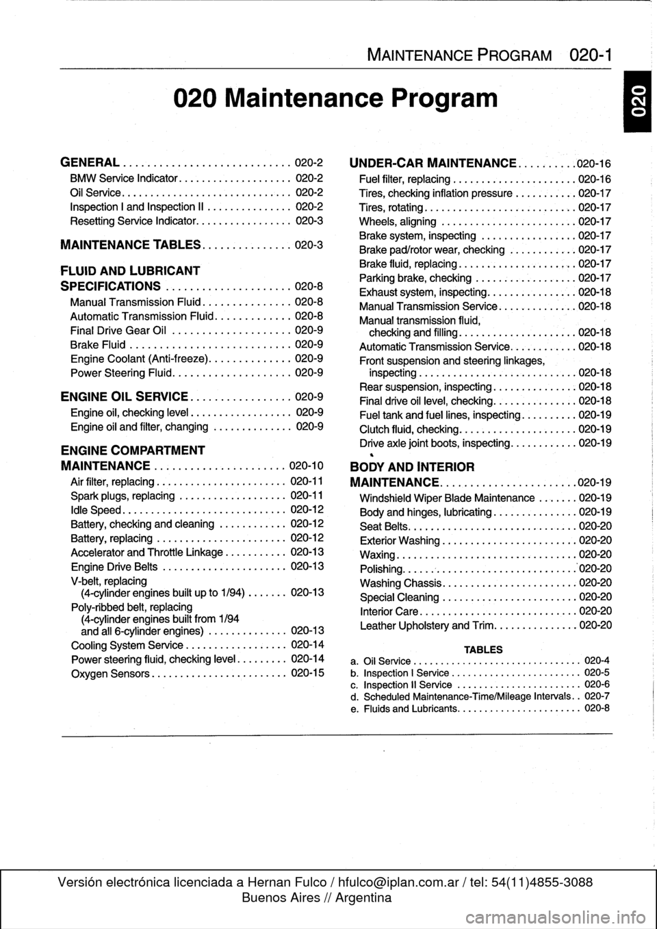
020
Maintenance
Program
GENERAL
.
.
...
.
.
.
...
.
.
.
.
.
.
.
.
.
.
.
...
.
..
020-2
BMW
Service
Indicator
......
..
....
..
...
..
.
020-2
Oil
Service
.....
.
..........
..
...
...
...
..
.
020-2
Inspection
I
and
Inspection
II
.
..
....
..
...
..
.
020-2
Resetting
Service
Indicator
....
.
....
..
...
..
.
020-3
MAINTENANCE
TABLES
..
.
.
.
.
.
........
020-3
FLUID
AND
LUBRICANT
SPECIFICATIONS
.
.
.
.
.
.
.
...
.
.
.
....
.
...
020-8
Manual
Transmission
Fluid
..
.
.
.
.
.
....
.
.
.
.
020-8
Automatic
Transmission
Fluid
.
.
.
.
.
....
.
.
.
.
020-8
Final
Drive
Gear
Oil
................
.
.
.
.
020-9
Brake
Fluid
.
.
.
.
.
................
.
.
.
.
020-9
Engine
Coolant
(Anti-freeze)
.
.
...
.
....
.
.
.
.
020-9
Power
Steering
Fluid
........
..
......
.
.
.
.
020-9
ENGINE
OIL
SERVICE
.
.
...
.
.
.
...
.
.
.
.
.
.
020-9
Engine
oil,
checking
leve¡
..
...
...
..
........
020-9
Engine
oil
and
filter,
changing
....
.
......
.
..
020-9
ENGINE
COMPARTMENT
MAINTENANCE
...
.
.
.
.
.
.
.
.
.
.
.
.
.
......
020-10
Air
filter,
replacing
.
...
...
.
.....
.
.....
.
...
020-11
Spark
plugs,
replacing
...
.
......
.
...
..
...
020-11
¡dle
Speed
.
..
...
...
....
.
......
.
...
..
...
020-12
Battery,
checking
and
cleaning
.......
..
...
020-12
Battery,
replacing
.
.....
.
.....
.
.....
..
...
020-12
Accelerator
and
Throttle
Linkage
.
.....
..
...
020-13
Engine
DriveBelts
.....
.
....
..
...
...
...
.
020-13
V-belt,
replacing
(4-cylinder
engines
built
up
to
1/94)
..
....
.
020-13
Poly-ribbed
belt,
replacing
(4-cylinder
engines
built
from
1194
and
all
6-cylinder
engines)
.
.
....
..
......
020-13
Cooling
System
Service
.
...
..
....
..
....
..
020-14
Power
steering
fluid,
checking
leve¡
.
..
....
.
.
020-14
Oxygen
Sensors
....
...
..
..
....
.
.....
.
.
020-15
MAINTENANCE
PROGRAM
020-1
UNDER-CAR
MAINTENANCE
.
..
.
...
.
.
.020-16
'
Fuel
filter,
replacing
...
.
.....
..
.....
..
..
.020-16
Tires,
checking
inflation
pressure
.
.....
.
....
020-17
Tires,
rotating
...
..
.....
..
....
..
....
.
....
020-17
Wheels,
aligning
..
.....
.
...........
.
....
'020-17
Brake
system,
inspecting
.
.
....
.
.....
..
...
020-17
Brake
pad/rotor
wear,checking
.
......
.
....
020-17
Brake
fluid,
replacing
.........
..
.
..
..
.
020-17
Parking
brake,
checking
......
.
.....
..
....
020-17
Exhaust
system,
inspecting
....
..
.....
.
...
.020-18
Manual
Transmission
Senrice
..
..
.....
.
....
020-18
Manual
transmission
fluida
checking
and
filling
..
.
....
..
.
.
..
..
....
020-18
AutomaticTransmission
Service
.
....
...
....
020-18
Front
suspension
and
steeringlinkages,
inspecting
..
.
:.....
.
....
..
.....
..
...
.
.020-18
Rear
suspension,
inspecting
.
..
...
...
....
..
020-18
Final
drive
oil
leve¡,
checking
.
.
.
...
....
...
..
020-18
Fuel
tank
and
fuel
lines,
inspecting
.
.....
....
020-19
Clutch
fluid,
checking
...
...
...
...
....
.....
020-19
Drive
axle
joint
boots,
inspecting
...
..
.....
..
020-19
BODY
AND
INTERIOR
MAINTENANCE
.
.
.
.
.
.
.
.
.
.
.
.
.
.
.
.
.
.
...
.
.020-19
Windshield
Wiper
Blade
Maintenance
....
.
.
020-19
Body
and
hinges,
lubricating
.
.....
..
......
.
020-19
Seat
Belts
...
..
...
...
...
..
.....
..
.....
.
.
020-20
Exterior
Washing
..
...
...
..
.
.
...
..
......
.020-20
Waxing
.....
..
...
...
...
..
.....
..
.......
020-20
Polishing
..
...
...
...
....
..
..........
..
.
.'020-20
Washing
Chassis
.
...
....
.
....
..
.....
.
...
020-20
Special
Cleaning
.
.
.....
..
...
.
.....
..
..
.020-20
Interior
Care
.
....
..
....
..
..
.
.
......
.
...
020-20
Leather
Upholstery
and
Trim
...
..
....
...
...
020-20
TABLES
a
.
Oil
Service
......
...
.
..
.............
...
---
020-4
b
.
Inspection
1
Service
..
.
.
.............
....
...
020-5
c
.
Inspection
11
Service
.
.
...
...........
..
.
..
..
020-6
d
.
Scheduled
Maintenance-Time/Mileage
Intervals
..
020-7
e
.
Fluids
and
Lubricants
..
...
...........
.....
..
020-8
Page 26 of 759
020-
4
MAINTENANCE
PROGRAM
L
~
~
c
.c
a
a>
mL
~
~L
L
w
a
£
'S
d
E
Maintenance
ítem
z
3
c
Engine
compartment
maintenance
Change
oil
and
oil
filter
Check
fluid
levels
(coolant,steering,
brake/clutch,
ATF)
Under
car
maintenance
Check
steeringrack
and
steeringlinkages
for
leaks
andexcess
play
.
Repair
Group
320
Inspect
brake
system
.
Check
brake
calipers,
rotors,
and
brake
pad
thíckness
.
Inspect
for
dam-
aged
hoses
and
lines,
leaks
or
damage
.
Check
hand
brake,adjust
cable
if
necessary
.
Repair
Group
340
Check
and
adjust
tire
pressures,
including
spare
Body
and
interior
maintenance
Check
operation
of
exterior
and
interior
lights,
including
glove
box
light,
engine
compartment
light,
trunk
light,
instrument
panel
lights,
horns,
headlight
flasher
anddimmer
switch
.
Check
headlight
and
driving
light
aiming
.
6
Electrical
System
Check
function/condition
of
seat
belts
.
Repair
Group
720
Check
windshield
washer
fluid
level
and
concentration,
add
as
necessary
.
Check
operation
of
washer
system
.
Check
condition
of
wiper
blades
.
Repair
Group
611
Road
Test
Check
braking
performance,
steering,
heating
and
ventilation,
manual
or
automatic
transmis-
sion,
and
mirrors
Service
Interval
Reset
Reset
service
indicator
using
specialreset
tool
.
MAINTENANCE
TABLES
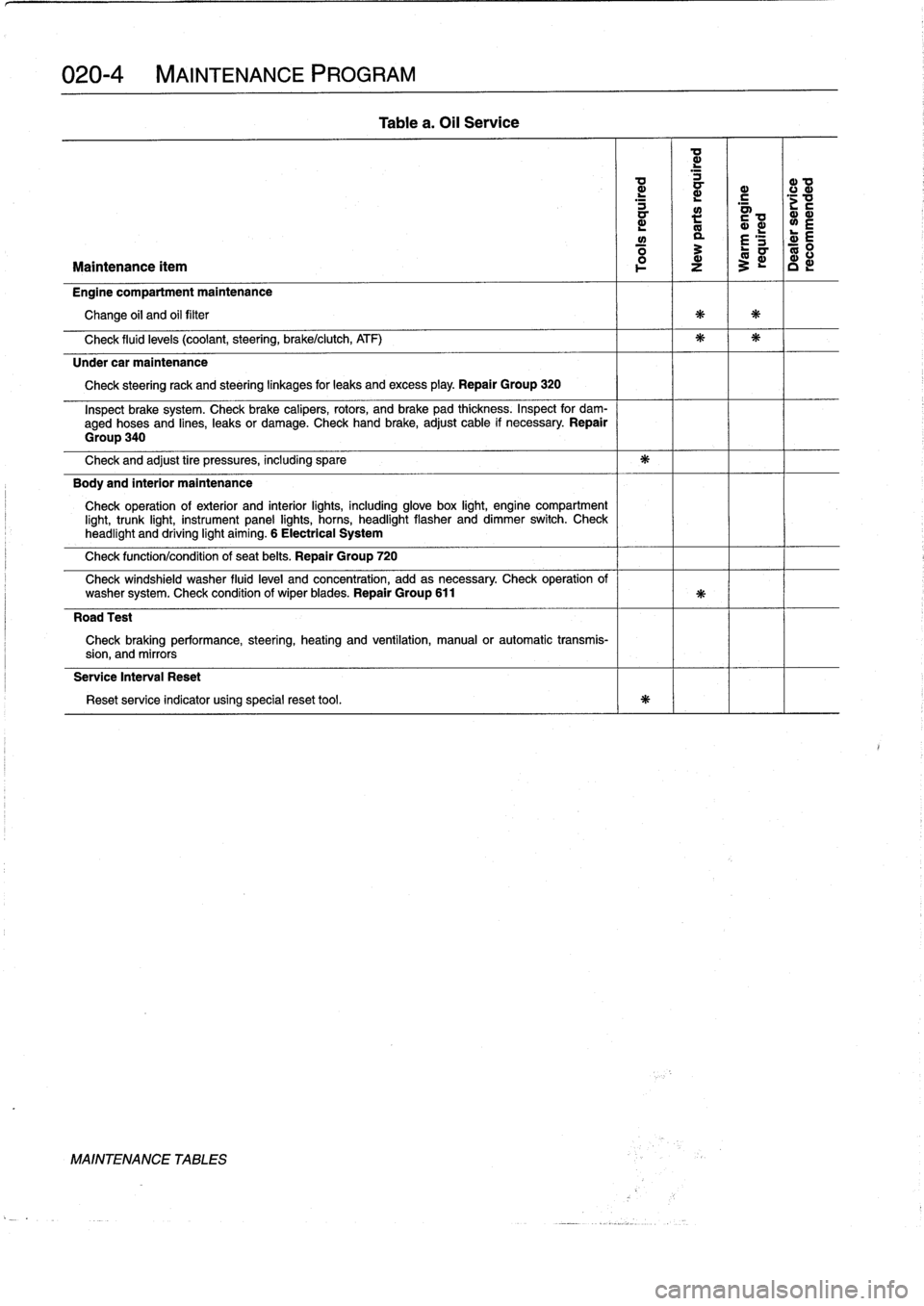
Table
a
.
Oil
Service
Page 27 of 759
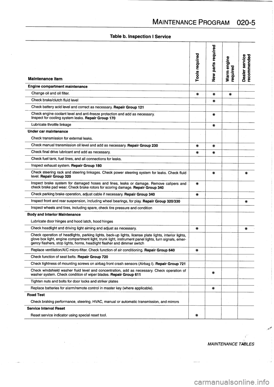
Table
b
.
Inspection
I
Service
MAINTENANCE
PROGRAM
020-5
ad
d
d
ID
a
r
c
d
a~
;v
a
:
Q~
wE
y
a
r
E
R
:
L-
0
Maintenance
ítem
1
z
3
~
c
d
Engine
compartment
maintenance
Change
oil
and
oil
filter
.
Check
brake/clutch
fluid
leve¡
Check
battery
acid
leve¡
and
correct
asnecessary
.
Repair
Group
121
Check
engine
coolant
level
and
anti-freeze
protection
and
addasnecessary
.
Inspect
for
cooling
system
leaks
.
Repair
Group
170
Lubricate
throttie
linkage
Under
car
maintenance
Check
transmission
for
externa¡
leaks
.
Check
manual
transmission
oil
leve¡
andadd
asnecessary
.
Repair
Group
230
Check
final
drive
lubricant
and
addasnecessary
.
Check
fue¡
tank,
fuel
lines,
and
all
connections
for
leaks
.
Inspect
exhaust
system
.
Repair
Group
180
Check
steeringrack
and
steeringlinkages
.
Check
power
steering
system
for
leaks
.
Check
(luid
leve¡
.
Repair
Group
320
Inspect
brake
system
for
damaged
hoses
and
fines,
leaks
or
damage
.
Remove
calipers
and
check
brake
pad
wear
.
Check
brake
rotors
for
scoring
damage
.
Repair
Group
340
Check
parking
brake
operation,
adjust
cable
if
necessary
Repair
Group
340
Inspect
front
and
rear
suspension,
including
wheel
bearings,
for
play
.
Repair
Group
320/330
Inspect
wheelsand
tires,
including
spare,
check
tire
pressure
and
condition
Body
and
Interior
Maintenance
Lubricate
door
hinges
and
hood
latch,
hood
hinges
Check
headlight
and
driving
light
aiming
and
adjust
as
necessary
.
Check
operation
of
headlights,
parking
lights,
back-up
fights,
licenseplate
lights,
interior
lights,
glove
box
light,
engine
compartment
light,
trunk
light,
instrument
panel
lights,
turnsignals,
emer-gency
flashers,
stop
fights,
horas,
headlight
flasher
and
dimmer
switch
Replace
ventilation/A/C
micro-filter
.
Check
functionof
air
conditioning
.
Repair
Group
640
Check
function
of
seat
belts
.
Repair
Group
720
Check
tightness
of
mountfng
screws
on
airbag
front
crash
sensors
(Airbag
I)
.
Repair
Group
721
Check
windshield
washer
fluid
leve¡
and
concentration,
add
as
necessary
Check
operation
of
washer
system
.
Check
condition
of
wiperblades
.
Repair
Group
611
Tighten
nuts
and
bolts
for
door
locks
and
striker
plates
Replace
batteries
for
alarm/remote
control
in
masterkey(where
applicable)
.
Road
Test
Check
braking
performance,
steering,
HVAC,
manual
or
automatic
transmission,
and
mirrors
Service
Interval
Reset
Reset
service
indicator
using
specialreset
tool
.
MAINTENANCE
TALES
Page 29 of 759
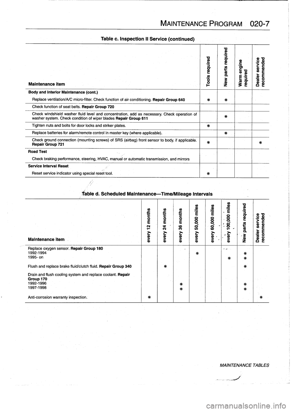
d
a
d
_
L
G>
G1
a
N
.
G1
Ñ
N
N
O
.
r
d
Maintenance
ítem
°
~
Z
~
i
I
D
i
Body
and
Interior
Maintenance
(cont
.)
Replace
ventilation/A/C
micro-filter
.
Check
function
of
air
conditioning
.
Repair
Group
640
Check
function
of
seat
belts
.
Repair
Group
720
Check
windshield
washer
fluid
level
and
concentration,
add
asnecessary
.
Check
operation
of
washer
system
.
Check
condition
of
wiperblades
Repair
Group
611
Tighten
nuts
and
belts
for
door
locks
and
striker
plates
.
Replace
batteries
for
alarm/remote
control
in
masterkey
(where
applicable)
.
Check
ground
connection
(mounting
screws)
of
SRS
(airbag)
front
sensor
to
body,
if
applicable
.
Repair
Group
721
Road
Test
Check
braking
performance,
steering,
HVAC,
manual
or
automatic
transmission,
and
mirrors
Service
Interval
Reset
Reset
service
indicator
using
specialreset
tool
.
Maintenance
ítem
Replace
oxygen
sensor
.
Repair
Group
180
1992-1994
1995-
on
Flush
and
replace
brake
fluid/clutch
fluid
.
Repair
Group
340
Drain
and
flush
cooling
system
and
replace
coolant
.
Repair
Group
170
1992-19961997-1998
Anti-corrosion
warranty
inspection
.
Tablec
.
Inspection
II
Service
(continued)
Cabled
.
Scheduled
Maintenance-Time/Mileage
Intervais
MAINTENANCE
PROGRAM
020-7
e
~
e
e
i
:
l=
N
l
"
NM
I
«)
al
aN
-
11
>
O
Ó
I
Ó
I`
Ó
d
Ny
.
0
°
_
VÑ
Ñ
Ñ
1
ZG
NN
MAÍNTENANCE
TABLES
Page 38 of 759

\
Catalytic
Oxygen
sensor
convertor
(monitoring)
Fig
.
21
.
Typical
1996
and
later
exhaust
system
showing
ox")
020-
1
6
MAINTENANCE
PROGRAM
Fuel
filter,
replacing
Oxygen
sensor
(regulating)
\
Catalytic
Oxygen
sensor
convertor
(monitoring)
Fig
.
21
.
Typical
1996
and
later
exhaust
system
showing
oxygen
sensor
locations
.
UNDER-CAR
MAINTENANCE
convertor
On
early
4-cylínder
cars,
the
fuel
filter
is
mounted
under
the
caron
the
left
front
bulkhead
.
On
early
6-cylínder
cars,
the
fuel
filter
is
mounted
to
the
front
left
motor
mount
in
theengine
com-
partment
.
See
Fig
.
22
.
0013139
Fig
.
22
.
Fuel
filter
location
(arrow)
on
bulkheadunder
left
side
of
vehi-
cle
.
Filter
for
M42
engine
shown
.
On
later
cars,
the
fuel
filter
is
located
beneath
the
centerof
the
car,
approximately
under
the
driver's
seat
.
See
Fig
.
23
.
A
protective
cover
is
installed
overthe
fuel
filter,
which
must
be
re-
moved
to
access
the
filter
.
UNDER-CAR
MAINTENANCE
Exhaust
flap
actuator
(monitoring)
NOTE-
Drain
the
fuel
filter
trom
the
inlet
side
into
a
container
and
inspect
the
drained
fuel
.
Check
for
rust,
moisture
and
contamination
.
WARNING
-
Fuel
will
be
expelled
when
the
filter
is
removed
.
Do
not
smoke
or
worknear
heaters
or'other
fire
haz-ards
.
Keep
a
tire
extinguisher
handy
.
CAUTION-
Clean
thoroughly
around
the
filter
connections
be-
fore
removing
them
.
0012726
Fig
.
23
.
Fuel
filter
location
under
center
of
car
(arrow)
.
Filter
for
M52
engine
shown
.
Catálytic
\
Oxygen
sensor
When
replacing
the
fuel
filter,
disconnect
the
battery
negative
(-)
cable
and
clamp
the
filter
inlet
and
outlet
hoses
to
lessen
fuel
spillage
.
Loosen
thecenter
clamping
bracket
and
the
two
hoseclampson
either
end
of
the
filter
.
Note
the
arrow
or
mark-
ings
indicating
direction
of
flow
on
the
new
filter
.
Install
the
filter
anduse
new
hose
clamps
.
Page 41 of 759
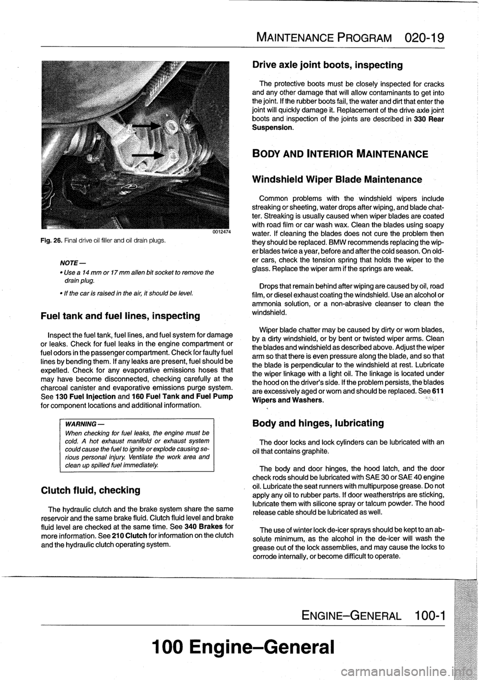
NOTE-
Use
a14
mm
or17
mm
alíen
bit
socket
to
remove
the
drain
plug
.
"
If
thecar
is
raised
in
the
air,
it
shouldbe
leve¡
.
Fuel
tank
and
fuel
fines,
inspecting
0012474
Inspect
the
fuel
tank,
fuel
lines,
and
fuel
system
for
damage
or
leaks
.
Check
for
fuel
leaks
in
the
engine
compartment
or
fuel
odors
in
the
passenger
compartment
.
Check
for
faultyfuel
lines
bybending
them
.
If
any
leaks
are
present,
fuel
should
be
expelled
.
Check
for
any
evaporative
emissions
hoses
that
may
have
become
disconnected,
checking
carefully
at
the
charcoal
canister
and
evaporative
emissionspurge
system
.
See130
Fuel
Injection
and
160
Fuel
Tank
and
Fuel
Pump
for
component
locations
and
additional
information
.
WARNING
-
When
checking
for
fuel
leaks,
the
engine
must
be
cold
.
A
hot
exhaust
manifold
or
exhaust
system
could
cause
the
fuel
to
ignite
or
explode
causing
se-
rious
personal
injury
.
Uentilate
the
workarea
and
clean
up
spilled
fuel
immediately
.
Clutch
fluid,
checking
The
hydraulic
clutch
and
the
brake
system
share
the
same
reservoir
and
the
same
brake
fluid
.
Clutch
fluid
leve¡
and
brake
fluid
level
are
checked
at
the
same
time
.
See340
Brakes
for
more
information
.
See210
Clutch
for
information
on
the
clutch
and
the
hydraulic
clutch
operating
system
.
MAINTENANCE
PROGRAM
020-19
Drive
axie
joint
boots,
inspecting
100
Engine-General
The
protective
boots
must
be
closely
inspected
for
cracks
andany
other
damage
that
will
allow
contaminants
to
get
ínto
the
joint
.
If
the
rubber
boots
faf
,
the
water
and
dirt
that
enter
the
joint
will
quickly
damage
¡t
.
Replacement
of
the
drive
axle
joint
boots
and
inspection
of
the
joints
are
described
in
330
Rear
Suspension
.
BODY
AND
INTERIOR
MAINTENANCE
Windshield
Wiper
Biade
Maintenance
Common
problems
with
the
windshield
wipers
include
streaking
or
sheeting,
water
drops
after
wiping,
and
blade
chat-
ter
.
Streaking
is
usually
caused
when
wiper
blades
are
coated
with
road
film
or
car
wash
wax
.
Clean
the
blades
using
soapy
water
.
If
cleaning
theblades
does
not
cure
the
problem
then
they
should
be
replaced
.
BMW
recommends
replacing
the
wip-
er
blades
twice
a
year,
before
and
after
the
cold
season
.
Onold-
er
cars,
check
the
tension
spring
that
holds
the
wiper
to
the
glass
.
Replace
the
wiper
arm
if
the
springs
are
weak
.
Drops
that
remainbehind
after
wipingare
caused
by
oil,
road
film,
or
diesel
exhaust
coating
the
windshield
.
Use
an
alcohol
or
ammonia
solution,
or
a
non-abrasive
cleanser
to
clean
the
windshield
.
Wiper
blade
chatter
may
be
caused
by
dirty
or
worn
blades,
bya
dirty
windshield,
or
by
bentor
twisted
wiper
arms
.
Clean
the
blades
and
windshield
as
described
above
.
Adjust
the
wiper
arm
so
that
there
is
even
pressure
along
the
blade,
and
so
that
the
blade
is
perpendicular
to
the
windshield
atrest
.
Lubricate
the
wiper
linkage
with
a
light
oil
.
The
linkage
is
located
under
the
hood
on
the
drivers
side
.
If
the
problem
persists,
theblades
are
excessively
aged
or
worn
and
should
be
replaced
.
See
611
Wipers
and
Washers
.
Body
and
hinges,
lubricating
The
door
locks
and
lock
cylinders
canbe
lubricated
with
an
oil
that
contains
graphite
.
The
body
and
door
hinges,
the
hood
latch,
and
the
door
check
rods
should
be
lubricated
with
SAE
30
or
SAE
40
engine
oil
.
Lubricate
the
seat
runners
with
multipurpose
grease
.
Do
not
apply
any
oil
to
rubber
parts
.
If
door
weatherstrips
are
sticking,
lubricate
them
with
silicone
spray
or
talcum
powder
.
The
hood
release
cable
should
be
lubricated
as
well
.
The
use
of
winter
lock
de-icer
spraysshould
be
kept
to
an
ab-
solute
minimum,
as
the
alcohol
in
the
de-icer
will
wash
the
grease
out
of
the
lock
assemblies,
and
may
cause
the
locks
to
corrode
internally,
or
become
difficult
to
operate
.
ENGINE-GENERAL
100-1
Page 42 of 759
020-20
MAINTENANCE
PROGRAM
Seat
Belts
Washing
Chassis
Dirt
and
other
abrasive
particles
will
damage
seat
belt
web-
Periodic
washing
of
the
underside
of
the
car,
especially
in
bing
.
If¡t
is
necessary
to
clean
seat
belts,
use
a
mild
soap
solu-
winter,
will
help
prevent
accumulation
of
road
salt
and
rust
.
The
tion
.
Bleach
and
other
strong
cleaning
agents
may
weaken
the
besttime
to
wash
the
underside
is
just
after
the
car
has
been
belt
webbing
and
should
be
avoided
.
driven
in
wet
conditions
.
Spray
the
chassis
with
a
powerful
jet
of
water
.
Commercial
or
self-service
car
washes
may
not
be
best
WARNING-
for
this,
as
they
may
recycle
the
salt-contaminated
water
.
Do
not
clean
the
seat
belt
webbing
using
dry
clean-
ing
or
other
chemicals
.
Allow
wet
belts
to
dry
before
allowing
them
to
retract
.
Speeial
Cleaning
The
condition
of
the
belt
webbing
and
the
function
of
the
re-
tractor
mechanisms
should
be
inspected
.
See720
Seat
Belts
for
seat
belt
inspection
information
.
Exterior
Washing
The
longer
dirt
isleft
on
the
paint,
the
greater
the
risk
of
dam-
aging
the
glossy
finish,
either
by
scratching
or
by
the
chemical
effect
dirt
particles
may
have
on
the
paintedsurface
.
Do
not
wash
the
car
in
direct
sunlight
.
If
the
engine
hood
is
warm,
allow
it
to
cool
.
Beads
of
water
not
only
leavespots
when
dried
rapidly
by
the
sun
or
heat
from
the
engine,
but
also
can
act
as
small
magnifyingglasses
and
burn
spots
into
the
finish
.
Wash
thecar
with
a
mixture
of
lukewarmwater
and
a
car
wash
product
.
Rinse
using
plenty
of
clear
water
.
Wipe
the
body
dry
witha
soft
cloth
towel
or
chamois
to
prevent
water-spotting
.
Waxing
For
a
long-lasting,protective,
and
glossy
finish,
apply
a
hard
wax
after
thecar
has
been
washed
and
dried
.
Use
carnauba
or
synthetic
based
products
.
Waxing
is
not
needed
after
every
washing
.
You
can
tell
when
waxing
is
required
by
looking
at
the
finísh
when
it
is
wet
.
If
the
water
coats
the
paint
in
smooth
sheets
instead
of
forming
beads
that
rol¡
off,
a
new
coat
of
wax
is
needed
.
Wax
shouldnot
be
applied
to
black
trim
pieces,
rub-
ber,or
other
plastic
parts
.
Polishing
Use
paintpolish
only
if
the
finish
assumes
a
dull
lock
after
long
service
.
Polish
can
beused
to
remove
tar
spots
and
tar-
nish,
but
afterwards
a
coat
of
wax
should
be
applied
to
protect
the
clean
finish
.
Do
not
use
abrasive
polish
or
cleaners
on
alu-
minum
trimor
accessories
.
BODYAND
INTERIOR
MAINTENANCE
Cylinder
Head
and
Valvetrain
The
aluminum
cylinder
head
uses
chain-driven
double
overhead
camshafts
and
four
valves
per
cylinder
.
See
Fig
.
1
.
Tha
rvfinriar
hand
nmnlnve
n
ernceflnier
rineinn
fnr
nronter
Tar
spots
canbe
removed
with
a
bugand
tar
remover
.
Never
use
gasoline,
kerosene,
nail
polish
remover,
or
other
unsuitable
solvents
.
Insect
spots
also
respond
to
tar
remover
.
A
bit
of
bak-
ing
soda
dissolved
in
the
wash
water
will
facilitate
their
removal
.
This
method
can
also
beused
to
remove
spotting
from
tree
sap
.
Interior
Care
Dirt
spots
can
usually
be
removed
with
lukewarm
soapy
wa-
ter
or
a
dry
foam
cleaner
.
Use
spot
remover
for
grease
and
o¡I
spots
.
Do
not
pour
the
(quid
directly
on
the
carpetor
fabric,
but
dampen
a
clean
cloth
and
rub
carefully,starting
at
the
edge
of
the
spot
and
working
inward
.
Do
not
use
gasoline,
naptha,
or
other
flammable
substances
.
Leather
Upholstery
and
Trim
Leather
upholstery
and
trim
should
be
periodically
cleaned
using
a
slightly
damp
cotton
or
wool
cloth
.
The
idea
is
to
get
rid
of
the
dirtin
the
creases
and
pores
that
can
cause
brittleness
and
premature
aging
.
On
heavily
soiled
areas,
usea
mild
deter-
gent
(such
as
Woolite®)
or
other
specially
formulated
leather
r
cleaners
.
Use
two
tablespoons
to
one
quart
of
cold
water
.
Dry
the
trim
and
upholstery
completely
using
a
soft
cloth
.
Regular
use
of
agood
quality
leather
conditioner
will
reduce
drying
and
crackingof
the
leather
.
1
.
Camshafts
2
.
Rocker
arms
3
.
Hydraulic
valve
adjusters
(HVA)
4
.
Valve
and
conical
valve
spring
Page 70 of 759
113-4
CYLINDER
HEAD
REMOVAL
AND
INSTALLATION
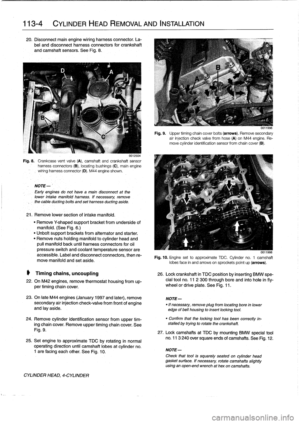
20
.
Disconnect
main
engine
wiring
harness
connector
.
La-
bel
and
disconnect
harness
connectors
for
crankshaft
and
camshaft
sensors
.
See
Fig
.
8
.
0012504
Fig
..
Crankcase
vent
valve
(A),
camshaft
and
crankshaft
sensor
harness
connectors
(B),
locating
bushings
(C),
main
engine
wiring
harnessconnector
(D)
.
M44
engine
shown
.
NOTE-
Early
engines
do
not
havea
maín
disconnect
at
the
lower
intake
manifold
harness
.
lf
necessary,
remove
the
cable
ducting
bolts
and
set
harness
ducting
aside
.
21
.
Remové
lower
section
of
intake
manifold
.
"
Remove
Y
shaped
supportbracket
from
underside
of
manifold
.
(See
Fig
.
6
.)
"
Unbolt
support
brackets
from
alternator
and
starter
.
"
Remove
nuts
holding
manifold
to
cylinder
head
and
pull
manifold
back
until
harness
connectors
for
oil
pressure
switch
and
coolant
temperature
sensorare
accessible
.
Label
and
disconnect
connectors,
then
re-
move
manifold
and
set
aside
.
Timing
chains,
uncoupling
26
.
Lock
crankshaft
in
TDC
position
by
insertíng
BMW
spe-
22
.
On
M42
engines,
remove
thermostat
housing
from
up-
cial
tool
no
.
11
2
300
through
bore
and
into
hole
infly-
per
timing
chaincover
.
wheel
or
driveplate
.
See
Fig
.
11
.
23
.
On
late
M44
engines
(January
1997
and
later),
remove
NOTE-
secondary
air
injection
check-valve
from
front
of
engine
"
If
necessary,
remove
plug
from
locating
bore
in
lower
and
lay
aside
.
edge
of
bell
housing
to
insert
locking
tool
.
24
.
Remove
cylinder
identification
sensor
from
upper
tim-
ing
chaincover
.
Remove
upper
timing
chaincover
.
See
Fig
.
9
.
25
.
Set
engine
to
approximate
TDC
by
rotating
in
normal
operating
direction
until
camshaft
lobes
at
cylinder
no
.
1
are
facing
each
other
.
See
Fig
.
10
.
CYLINDER
HEAD,
4-CYLINDER
Fig
.
9
.
Upper
timing
chain
cover
bolts
(arrows)
.
Remove
secondary
air
injection
check
valve
fromhose
(A)
on
M44
engine
.
Re-
move
cylinder
identification
sensor
from
chaincover
(B)
.
0011998
Fig
.
10
.
Engine
set
to
approximate
TDC
.
Cylinder
no
.
1
camshaft
lobes
face
in
and
arrows
on
sprockets
poínt
up
(arrows)
.
"
Confirm
that
the
locking
tool
has
been
correctly
in-
stalled
by
trying
to
rotate
the
crankshaft
.
27
.
Lock
camshafts
at
TDC
by
mounting
BMW
specíal
tool
no
.
113
240
over
square
ends
of
camshafts
.
See
Fig
.
12
.
NOTE-
Check
that
tool
is
squarely
seated
on
cylinder
head
gasket
surface
.
If
necessary,
rotate
camshafts
slightly
using
an
open-end
wrench
at
hex
oncamshafts
.
Page 79 of 759
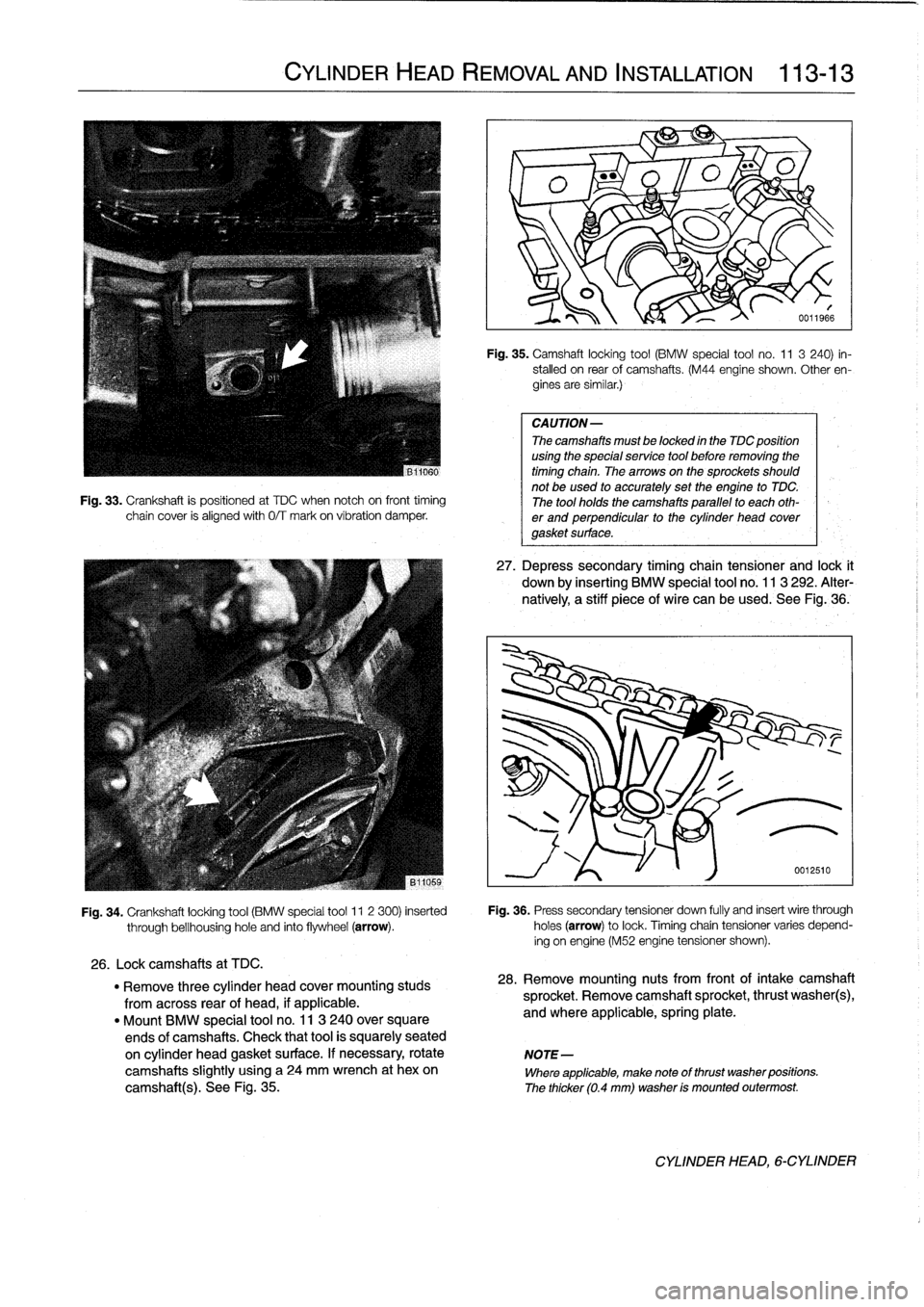
Fig
.
33
.
Crankshaft
is
positioned
at
TDC
when
notch
oh
front
timing
chain
cover
is
alignedwith
0/T
mark
on
víbration
damper
.
CYLINDER
HEAD
REMOVAL
AND
INSTALLATION
113-
1
3
Fig
.
35
.
Camshaft
locking
tool
(BMW
special
tool
no
.
11
3
240)
in-
stalled
on
rear
of
camshafts
.
(M44
engine
shown
.
Other
en-
gines
are
similar
.)
CAUTION-
The
camshafts
must
be
locked
in
the
TDC
position
using
the
special
service
tool
before
removing
the
timing
chain
.
Thearrowson
the
sprockets
should
not
be
used
to
accurately
set
the
engine
to
TDC
.
The
tool
holds
the
camshafts
parallel
to
each
oth-
er
and
perpendicular
to
the
cylinder
head
covergasket
surface
.
27
.
Depress
secondary
timing
chain
tensioner
and
lock
t
down
by
inserting
BMW
special
tool
no
.
113
292
.
Alter-
natively,
a
stiff
piece
of
wire
can
be
used
.
See
Fig
.,36
.
Fig
.
34
.
Crankshaft
locking
tool
(BMW
special
tool
11
2
300)
inserted
Fig
.
36
.
Press
secondary
tensioner
down
fully
and
insert
wire
through
through
bellhousinghole
and
finto
flywheel
(arrow)
.
holes
(arrow)
to
lock
.
Timingchain
tensioner
varies
depend-
ing
on
engine
(M52
engine
tensioner
shown)
.
26
.
Lockcamshafts
at
TDC
.
"
Remove
three
cylinder
head
cover
mounting
studs
28
.
Remove
mounting
nuts
from
front
of
intake
camshaft
from
across
rear
of
head,
if
applicable
.
sprocket
.
Remove
camshaft
sprocket,
thrust
washer(s),
"
Mount
BMW
special
tool
no
.
11
3
240
over
square
and
where
applicable,
spring
plate
.
ends
of
camshafts
.
Check
that
tool
is
squarely
seated
on
cylinder
head
gasket
surface
.
If
necessary,
rotate
NOTE-
camshafts
slightly
using
a
24
mm
wrench
at
hexon
Where
applicable,
make
note
of
thrust
washer
positions
.
camshaft(s)
.
See
Fig
.
35
.
The
thicker
(0
.4
mm)
washer
is
mounted
outermost
.
CYLINDER
HEAD,6-CYLINDER