wheel bolt torque BMW 328i 1995 E36 Owner's Guide
[x] Cancel search | Manufacturer: BMW, Model Year: 1995, Model line: 328i, Model: BMW 328i 1995 E36Pages: 759
Page 270 of 759
320-
4
STEERING
AND
WHEEL
ALIGNMENT
7
.
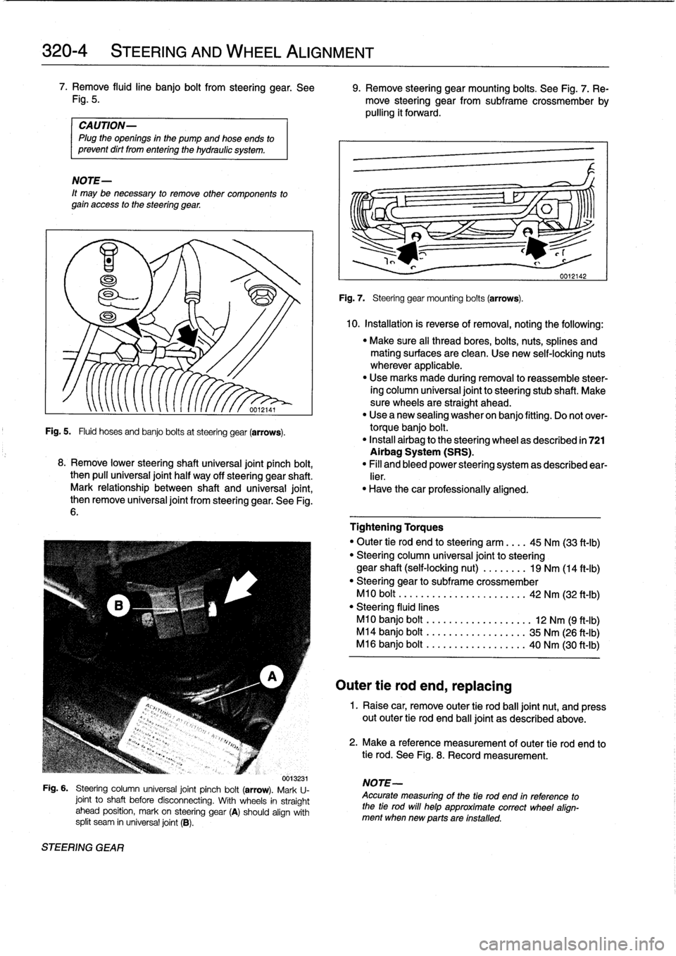
Remove
fluidline
banjo
bolt
from
steering
gear
.
See
9
.
Remove
steering
gearmounting
bolts
.
See
Fig
.
7
.
Re
Fig
.
5
.
move
steering
gear
from
subframe
crossmember
by
pulling
it
forward
.
CAUTION-
Plug
the
openings
in
the
pump
and
hoseends
to
prevent
dirt
from
entering
the
hydraulic
system
.
NOTE-
It
may
be
necessary
to
remove
other
components
to
gain
access
to
the
steering
gear
.
"
Make
sure
al¡
thread
bores,
bolts,
nuts,
splines
and
mating
surfaces
are
clean
.
Use
new
self-locking
nuts
wherever
applicable
.
"
Use
marks
made
during
removal
to
reassemble
steer-
ing
column
universal
jointto
steering
stub
shaft
.
Make
sure
wheels
are
straight
ahead
.
"
Use
a
new
sealing
washer
on
banjo
fitting
.
Do
not
over-
Fig
.
5
.
Fluid
hoses
and
banjo
bolts
at
steering
gear
(arrows)
.
torque
banjo
bolt
.
"
Install
airbag
to
the
steering
wheel
as
described
in
721
Airbag
System
(SRS)
.
8
.
Remove
lower
steeringshaft
universal
joint
pinch
bolt,
"
Fill
and
bleed
power
steering
system
as
described
ear-
then
pull
universal
joint
half
way
off
steering
gear
shaft
.
lier
.
Mark
relationship
between
shaft
and
universal
joint,
"
Have
thecar
professionally
aligned
.
then
remove
universal
joint
from
steering
gear
.
See
Fig
.
6
.
0013231
Fig
.
6
.
Steering
column
universal
joint
pinch
bolt
(arrow)
.
Mark
U-
joint
to
shaft
before
disconnecting
.
With
wheels
in
straight
ahead
position,
mark
on
steering
gear
(A)
should
align
with
split
seam
in
universal
joint
(B)
.
STEERING
GEAR
Fig
.
7
.
Steering
gear
mounting
bolts
(arrows)
.
Outer
tie
rod
end,
replacing
10
.
Installation
is
reverse
of
removal,
noting
the
following
:
Tightening
Torques
"
Outer
tie
rod
end
to
steering
arm
.
.
..
45
Nm
(33
ft-Ib)
"
Steering
column
universal
joint
to
steering
gear
shaft
(self-locking
nut)
....
..
..
19
Nm
(14
ft-Ib)
"
Steering
gear
to
subframe
crossmember
M10
bolt
..............
.
...
.....
42
Nm
(32
ft-Ib)
"
Steering
fluíd
lines
M10
banjo
bolt
..
..
..
........
.....
12
Nm
(9
ft-Ib)
M14
banjo
bolt
..
..
..
...
..
...
....
35
Nm
(26
ft-lb)
M16
banjo
bolt
..
.......
..
..
.....
40
Nm
(30
ft-Ib)
1
.
Raise
car,
remove
outer
tie
rod
ball
joint
nut,
and
press
out
outer
tie
rod
end
ball
joint
as
described
above
.
2
.
Make
a
reference
measurement
of
outer
tie
rod
end
to
tie
rod
.
See
Fig
.
8
.
Record
measurement
.
NOTE-
Accurate
measuring
of
the
tie
rod
end
in
reference
to
the
tie
rod
will
help
approximate
correct
wheel
align-
mentwhen
new
parts
are
installed
.
Page 274 of 759
330-2
REAR
SUSPENSION
Table
a
.
Rear
RideHeight
Specifications
Wheel
size
318,323,
325,
M3
modeis
328
modeis
17inch
std
.
suspension
546
mm
(21.69
in)
sport
suspension
~
535
mm
(21.06
in)
1
540
mm
(21
.26
in)
Maximum
variation
between
sides
:
10
mm
(0
.4in)
Maximum
deviation
from
specifications
:
10
mm
(0
.4in)
SHOCK
ABSORBERS
AND
SPRINGS
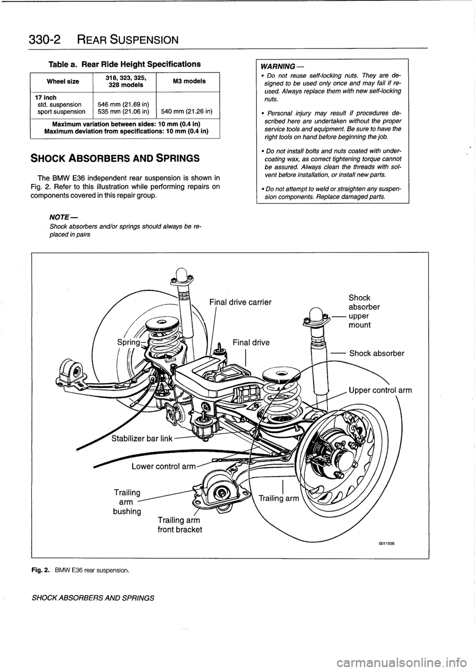
The
BMW
E36
independent
rear
suspension
is
shown
in
Fig
.
2
.
Refer
tothis
illustration
while
performing
repairs
on
components
covered
in
this
repair
group
.
NOTE-
Shock
absorbers
andlor
springs
shouldalways
be
re-
placed
in
pairs
i
Stabilizer
bar
link
Trailing
arm
-
bushing
Fig
.
2
.
BMW
E36
rear
suspension
.
SHOCK
ABSORBERS
AND
SPRINGS
Lower
control
arm
Trailing
arm
front
bracket
WARNING
-
"
Do
not
reuse
self-locking
nuts
.
They
arede-
signed
to
beused
only
once
and
may
fail
if
re-
used
.
Always
replace
them
with
new
self-locking
nuts
.
"
Personal
injury
may
result
if
procedures
de-
scribed
here
are
undertaken
without
the
proper
service
tools
and
equipment
.
Be
sure
to
have
the
right
tools
onhand
before
beginning
the
job
.
"
Do
not
install
bolts
and
nuts
coated
with
under-
coating
wax,
as
correct
tightening
torque
cannot
be
assured
.
Always
clean
the
threads
with
sol-
vent
before
installation,
or
ínstall
new
parts
.
"
Do
not
attempt
to
weld
or
straighten
any
suspen-
sion
components
.
Replace
damaged
parts
.
Page 276 of 759
330-
4
REAR
SUSPENSION
7
.
Installation
is
reverse
ofremoval,
noting
the
following
:
"
Make
sure
all
threaded
bolts,
nuts
and
makng
surfaces
are
clean
.
"
Instan
shock
absorber
finto
shock
tower
using
a
new
uppermounting
gasket
and
new
self-locking
nuts
.
"
Tighten
lower
boltto
its
final
torque
oncecar
is
on
ground
.
Tightening
Torques
"
Road
wheel
to
hub
.........
100±10
Nm
(74±7
ft-Ib)
"
Shock
absorber
to
trailing
arm
(car
in
normalloaded
position)
......
77
Nm
(57
ft-Ib)
"
Shock
absorber
to
upper
mount
.....
14
Nm
(10
ft-Ib)
"
Shock
absorber
upper
mount
to
body
(M8
self-locking
nuts)
.............
24
Nm
(17
ft-Ib)
Coil
spring,
removing
and
installing
WARNING
-
"
The
coil
spring
is
undercompressive
force
and
ís
extremely
dangerous
until
compression
isre-
moved
.
"
lt
is
recommended
that
a
restraining
chain
be
in-
stalled
between
the
bottomof
the
coil
spring
and
the
upper
control
arm
to
retain
the
spring
in
case
of
accidental
release
.
Personal
injury
can
result
if
the
compressed
coil
spring
is
not
released
slowly
and
carefully
.
"
Make
sure
that
the
car
is
firmly
supported
on
jack
standsdesigned
for
the
purpose
.
Place
the
jack
standsbeneatha
structural
chassis
point
.
Do
not
place
jack
stands
under
suspension
parts
.
1
.
Raise
car
and
remove
rear
wheel
.
2
.
Support
suspension
arm
from
below
using
a
transmis-
sion
jack
orequívalent
.
Tightening
Torques
3
.
Remove
drive
axle
from
final
drive
.
See
Fig
.
6
.
Suspend
"
Drive
axle
to
final
drive
flange
drive
axle
from
chassis
using
stiff
wire
.
M8
Torx
bolt
.
..
...
.
.............
64
Nm
(47
ft-Ib)
M10
Torx
bolt
...................
83
Nm
(62
ft-Ib)
4
.
Disconnect
shock
absorber
from
traíling
arm
.
"
Road
wheel
to
hub
.........
100±10
Nm
(74±7
ft-Ib)
"
Shock
absorber
to
trailing
arm
......
77
Nm
(57
ft-Ib)
5
.
Lower
suspension
slowly
and
carefully
until
the
com-
pressed
coil
spring
is
fully
unloaded
.
CAUTION
-
The
shock
absorber
prevents
the
drive
axle
and
trailíng
arm
from
drooping
too
far,
so
always
sup-port
the
trailing
arm
before
removing
the
shock
.
Damage
to
drive
axle
CV
joints
can
result
.
6
.
Remove
restraining
chain
and
remove
coi¡
spring
.
REAR
WHEEL
BEARINGS
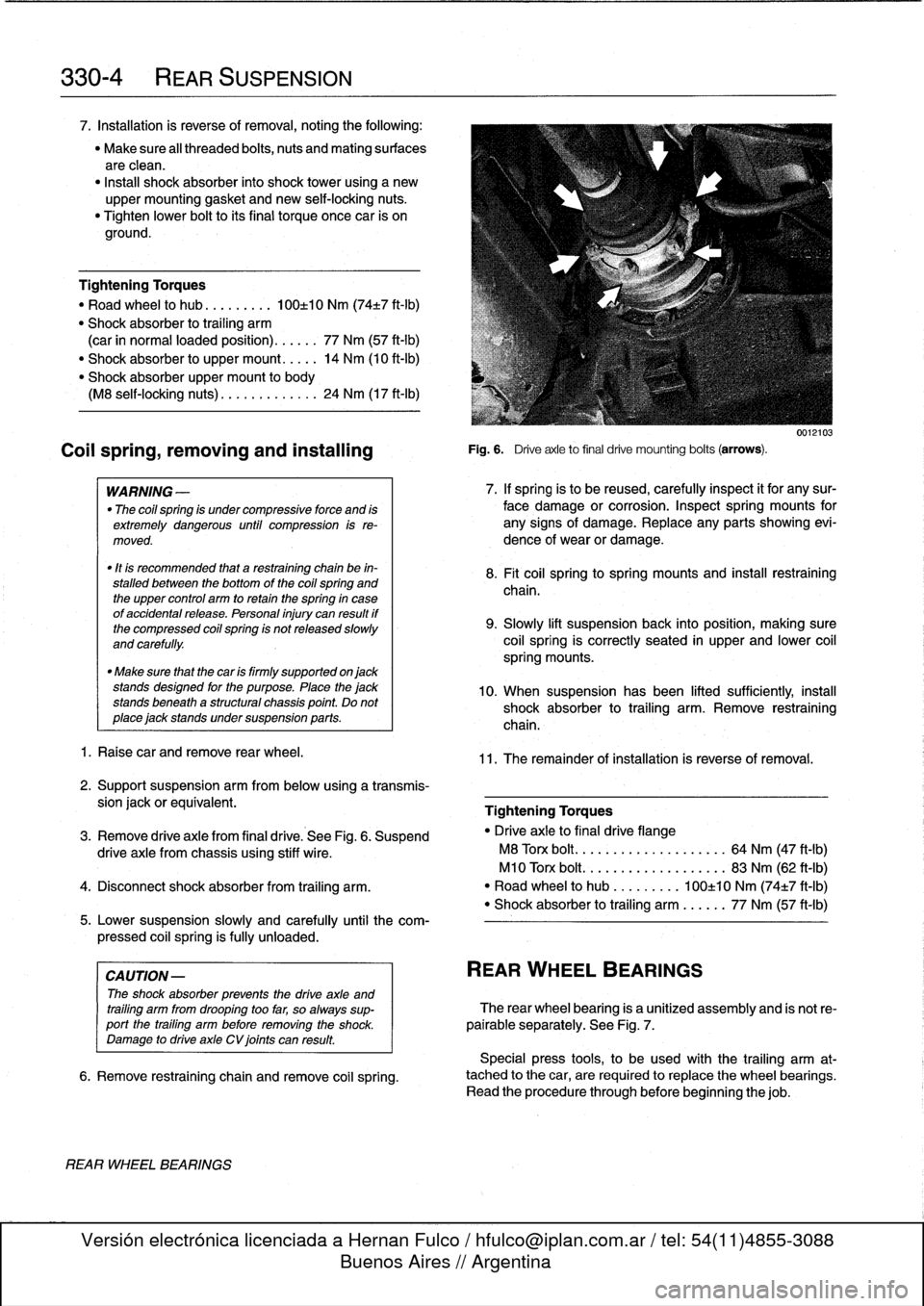
Fig
.
6
.
Driveaxle
to
final
drive
mounting
bolts
(arrows)
.
0012103
7
.
If
spring
is
to
be
reused,
carefully
inspect
it
for
any
sur-
face
damage
or
corrosion
.
Inspect
spring
mounts
for
any
signs
of
damage
.
Replace
any
parts
showing
evi-
dence
of
wear
or
damage
.
8
.
Fit
coil
springtospring
mountsand
insta¡¡
restraíning
chaina
9
.
Slowly
lift
suspensionback
into
position,
making
sure
coil
spring
is
correctly
seated
in
upper
and
lower
coil
spring
mounts
.
10
.
When
suspension
has
been
lifted
sufficiently,
instan
shock
absorber
to
trailing
arm
.
Remove
restraining
chain
.
11
.
The
remainder
of
installation
is
reverse
of
removal
.
REAR
WHEEL
BEARINGS
The
rear
wheel
bearing
is
a
unitized
assembly
and
is
not
re-
pairable
separately
.
See
Fig
.
7
.
Special
press
tools,
to
be
used
with
the
trailing
arm
at-
tached
to
the
car,
are
requiredto
replace
the
wheel
bearings
.
Read
the
procedure
through
before
beginning
thejob
.
Page 279 of 759
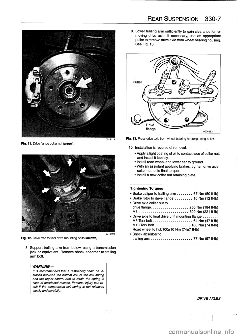
Fig
.
11
.
Drive
flange
collar
nut
(arrow)
.
0012111
8
.
Support
trailing
arm
from
below,
using
a
transmission
jackorequivalent
.
Remove
shock
absorber
to
trailing
arm
bolt
.
WARNING
-
It
is
recommended
that
a
restraining
chain
be
in-
stalled
between
the
bottom
coil
of
the
coil
spring
and
the
upper
control
arm
to
retain
thespring
in
case
of
accidental
release
.
Personal
injury
can
re-
sult
if
the
compressed
coil
spring
is
not
released
slowly
and
carefully
.
REAR
SUSPENSION
330-
7
9
.
Lower
trailing
arm
sufficiently
to
gain
clearance
for
re-
moving
drive
axle
.
If
necessary
use
an
appropriate
puller
to
Rmove
drive
axle
from
wheel
bearing
housing
.
See
Fig
.
13
.
10
.
Installation
is
reverse
of
removal
.
Fig
.
13
.
Press
drive
axle
from
wheel
bearing
housing
using
puller
.
"
Apply
a
light
coating
of
oil
to
contact
face
of
collar
nut,
and
install
it
loosely
.
"
Install
road
wheel
and
lower
car
to
ground
.
"
With
an
assistant
applying
brakes,
tighten
drive
axle
collar
nut
to
its
final
torque
.
"
Install
a
new
collar
nut
retaining
plate
.
Tightening
Torques
"
Brake
caliper
to
trailing
arm
........
67
Nm
(50
ft-Ib)
"
Brake
rotor
to
drive
flange
.........
16
Nm
(12
ft-Ib)
"
Drive
axle
collar
nut
to
drive
flange
.
.
....
..
.
..........
250
Nm
(184
ft-Ib)
M3
......
.
.
.....
.
.
..........
300
Nm
(221
ft-Ib)
"
Drive
axie
to
final
drive
unit
mounting
flange
.
.
.
.....
M8
Torx
bolt
.
...
...
.
............
64
Nm
(47
ft-Ib)
M10
Torx
bolt
...
...............
100
Nm
(74
ft-Ib)
Road
wheel
to
hub100±10
Nm
(74t7
ft-Ib)
0012103
"
Shock
absorber
to
Fig
.
12
.
Drive
axle
to
final
drive
mounting
bolts
(arrows)
.
trailing
arm
.
.
...
...
.
............
77
Nm
(57
ft-Ib)
DRIVE
AXLES
Page 283 of 759
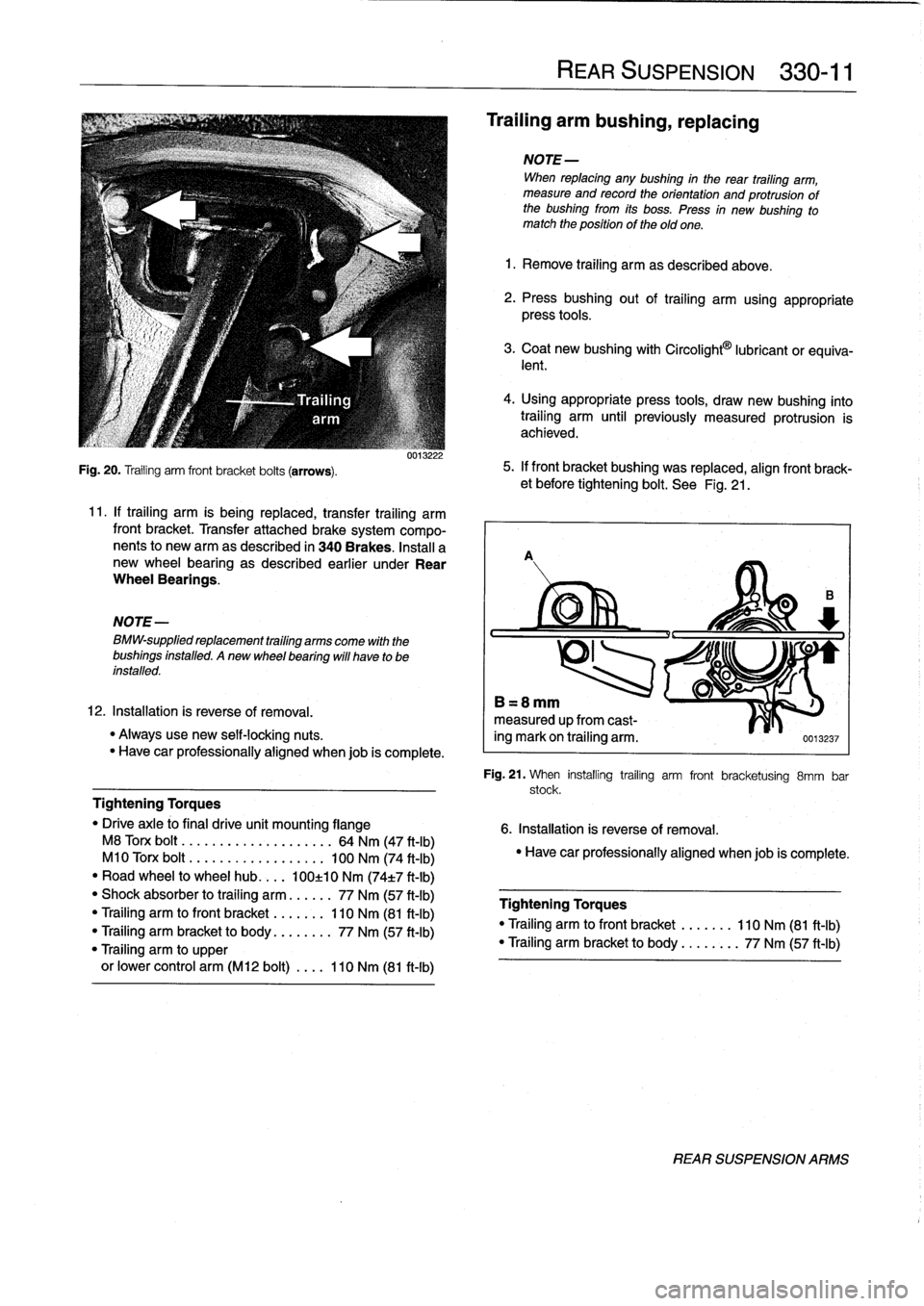
Fig
.
20
.
Trailing
arm
front
bracket
bolts
(arrows)
.
NOTE-
BMW-supplied
replacement
trailing
arms
come
with
the
bushings
installed
.
Anew
wheel
bearing
will
have
to
be
installed
.
0013222
11
.
If
trailing
arm
is
being
replaced,
transfer
trailing
arm
front
bracket
.
Transfer
attached
brake
system
compo-
nents
to
newarm
as
described
in
340Brakes
.
Insta¡¡
a
new
wheel
bearing
as
described
earlier
under
Rear
Wheel
Bearings
.
12
.
Installation
is
reverse
of
removal
.
"
Alwaysuse
new
self-locking
nuts
.
"
Have
car
professionally
aligned
when
job
is
complete
.
Tightening
Torques
"
Drive
axle
#o
final
drive
unit
mounting
flange
M8
Torx
bolt
......
.
...
.....
.
..
..
64
Nm
(47
ft-Ib)
M10
Torx
bolt
.....
...
.
....
.....
100
Nm
(74
ft-Ib)
"
Road
wheel
to
wheel
hub
.
...
100±10
Nm
(74t7
ft-Ib)
"
Shock
absorber
to
trailing
arm
......
77
Nm
(57
ft-Ib)
"
Trailing
arm
tofront
bracket
.......
110
Nm
(81
ft-Ib)
"
Trailing
arm
bracket
to
body
........
77
Nm
(57
ft-Ib)
"Trailing
arm
to
upper
or
lower
control
arm
(M12
bolt)
....
110
Nm
(81
ft-Ib)
REAR
SUSPENSION
330-
1
1
Trailing
arm
bushing,
replacing
NOTE-
When
replacing
any
bushing
in
the
rear
trailing
arm,
measure
and
recordthe
orientation
and
protrusion
of
the
bushing
from
its
boss
.
Press
in
new
bushing
to
match
the
positionof
theold
one
.
1
.
Remove
trailing
arm
as
described
above
.
2
.
Pressbushing
out
of
trailing
arm
using
appropriate
press
tools
.
3
.
Coat
new
bushing
with
Circolight
9
lubricant
or
equiva-
lent
.
4
.
Using
appropriate
press
tools,
draw
new
bushing
into
trailing
arm
until
previously
measured
protrusion
is
achieved
.
5
.
If
front
bracket
bushing
was
replaced,
alignfront
brack-
et
before
tightening
bolt
.
See
Fig
.
21
.
A
B=8mm
measured
upfrom
cast-
ing
mark
on
trailing
arm
.
0013237
Fig
.
21
.
When
installing
trailing
arm
front
bracketuising
8mm
bar
stock
.
6
.
Installation
is
reverse
of
removal
.
"
Have
car
professionally
aligned
when
job
is
complete
.
Tightening
Torques
"
Trailing
arm
tofront
bracket
.......
110
Nm
(81
ft-Ib)
"Trailing
arm
bracket
to
body
......
.
.
77
Nm
(57
ft-Ib)
REAR
SUSPENSION
ARMS
Page 284 of 759
330-
1
2
REAR
SUSPENSION
Upper
control
arm,
removing
and
installing
1.
Raise
rear
end
of
car
and
remove
wheel
.
WARNING
-
Make
sure
that
the
car
is
firmly
supportedon
jack
stands
designed
for
the
purpose
.
Place
the
jack
stands
beneatha
structural
chassis
point
.
Do
not
place
jack
stands
under
suspension
parts
.
2
.
Remove
drive
axle
as
described
earlier
.
3
.
Remove
stabilizer
bar
link
fromupper
control
arm
.
4
.
Support
trailing
arm
from
below
with
a
transmission
jackorequivalent
.
WARNING
-
It
is
recommended
that
a
retaining
chain
be
in-
stalled
between
the
bottom
coil
of
the
coil
spring
and
the
upper
control
arm
to
retain
thespring
in
case
of
accidental
release
.
Personal
injury
can
re-
sult
if
the
compressed
coil
spring
ís
not
released
slowly
and
carefully
.
5
.
Remove
lower
shock
absorber
bolt
.
Refer
to
Fig
.
18
.
Slowly
lower
trailing
arm
until
coil
spring
is
fully
re-
leased
.
Remove
restraining
chain
and
remove
spring
.
7
.
Installation
is
reverse
of
removal
.
"
Always
use
new
self-locking
nuts
.
"
Have
car
professionally
aligned
when
job
is
complete
.
"
Insta¡¡
drive
axle
as
described
earlier
.
Tightening
Torques
"
Drive
axleto
final
drive
flange
M8
Torx
bolt
..........
..
.
..
....
64
Nm
(47
ft-Ib)
M10
Torx
bolt
.........
..
..
.
...
100
Nm
(74
ft-Ib)
"
Shock
absorber
to
trailing
arm
..
..
..
77
Nm
(57
ft-Ib)
"
Upper
control
arm
to
final
drive
carrier
(M12
bolt)
...
..
.
77
Nm
(57
ft-Ib)
"
Upper
control
arm
to
trailing
arm
(M12
bolt)
.........
110
Nm
(81
ft-Ib)
Lower
control
arm,
1
.
Raise
rear
end
of
car
and
support
it
securely
on
jack-
stands
.
Remove
rear
wheel
.
2
.
Remove
both
lower
control
arm
mounting
bolts
.
FINAL
DRIVE
CARRIER
3
.
Use
a
soft
hammer
to
tap
control
arm
out
of
its
mount-
ing
points
.
4
.
Installation
is
reverse
of
removal
.
NOTE-
Use
a
new
bolt
and
washer
assembly
at
the
final
drive
carrier
mountíng
point
forthe
control
arm
.
Tightening
Torque
"
Lower
control
arm
to
final
drive
carrier
(M12
bolt)
......
77
Nm
(57
ft-Ib)
"
Lower
control
arm
to
trailing
arm
(M12
bolt)
....
..
.
..
110
Nm
(81
ft-Ib)
FINAL
DRIVE
CARRIER
Final
drive
carrier,
removing
and
installing
1
.
Raise
rear
end
of
car
and
support
it
securely
on
jack
stands
.
Remove
rear
wheels
.
2
.
Remove
driveshaft
.
See
260
Driveshaft
.
3
.
Remove
both
drive
axles
as
described
earlier
.
6
.
Remove
both
upper
control
arm
mounting
bolts
.
Re-
move
control
arm
.
4
.
Disconnect
stabilizer
bar
from
upper
control
arms
.
Re-
move
stabilizer
bar
mounts
.
5
.
Disconnect
speedometer
harness
connector
on
final
drive
(where
applicable)
.
6
.
Remove
rear
section
of
exhaust
system
.
See
180
Ex-
haust
System
.
NOTE-
It
may
be
easier
to
remove
complete
exhaust
asonepiece
.
See
180
Exhaust
System
.
7
.
Remove
upper
and
lower
control
arms
as
described
earlier
.
8
.
Support
final
drive
carrierwith
transmissíon
jack
.
Re-
move
mounting
bolts
and
nuts
at
final
drive
carrier
bushing
mounts
.
See
Fig
.
22
.
9
.
Slowly
lower
final
drive
and
final
drive
carrier,
detaching
removing
and
installing
wire
harness
and
connectors
as
necessary
.
10
.
Finaldrive
may
now
be
unbolted
from
final
drive
carrier
.
Page 285 of 759
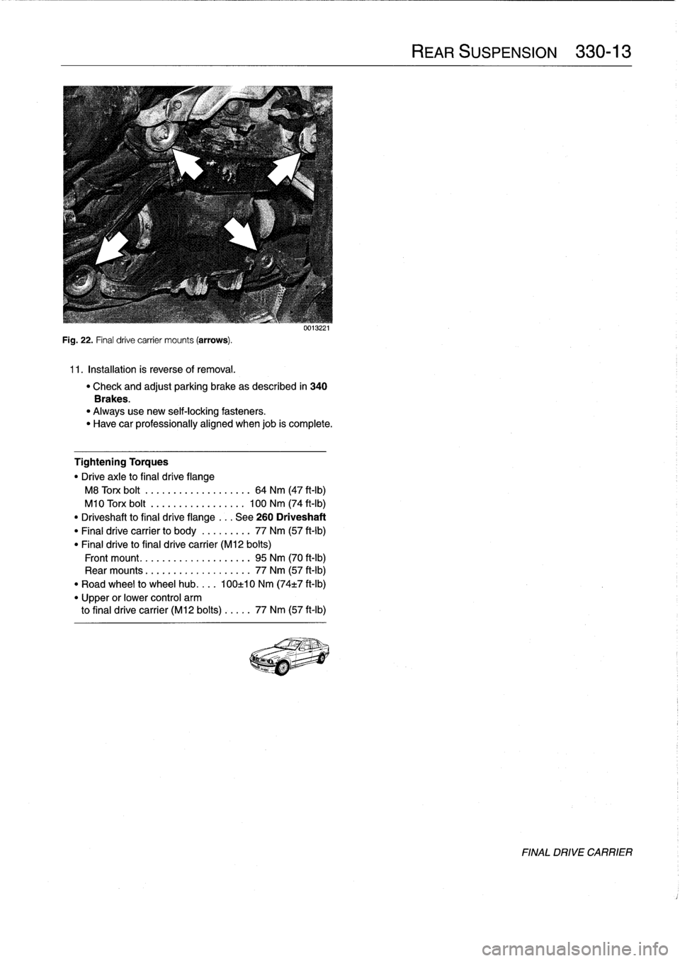
Fig
.
22
.
Final
drive
carrier
mounts
(arrows)
.
11
.
Installation
is
reverse
of
removal
.
uu1J221
"
Check
and
adjust
parking
brake
as
described
in
340
Brakes
.
"
Alwaysuse
new
self-locking
fasteners
.
"
Have
car
professionally
aligned
when
job
is
complete
.
Tightening
Torques
"
Drive
axle
to
final
drive
flange
M8
Torx
bolt
................
...
64
Nm
(47
ft-Ib)
M10
Torx
bolt
..........
..
...
.
.
100
Nm
(74
ft-Ib)
"
Driveshaft
to
final
drive
flange
...
See
260
Driveshaft
"
Final
drive
carrier
to
body
......
...
77
Nm
(57
ft-Ib)
"
Final
drive
to
final
drive
carrier
(M12
bolts)
Front
mount
.................
...
95
Nm
(70
ft-lb)
Rear
mounts
................
...
77
Nm
(57
ft-Ib)
"
Road
wheel
to
wheel
hub
....
100±10
Nm
(74t7
ft-Ib)
"
Upper
or
lower
control
arm
to
final
drive
carrier
(M12
bolts)
....
.
77
Nm
(57
ft-Ib)
Page 289 of 759
Final
driveinputshaft
oil
sea¡,
replacing
1
.
Raise
car
and
support
safely
.
2
.
Drain
final
drive
oil
as
described
earlier
.
3
.
Remove
driveshaft
from
final
drive
inputshaft
flange
.
See
260
Driveshaft
.
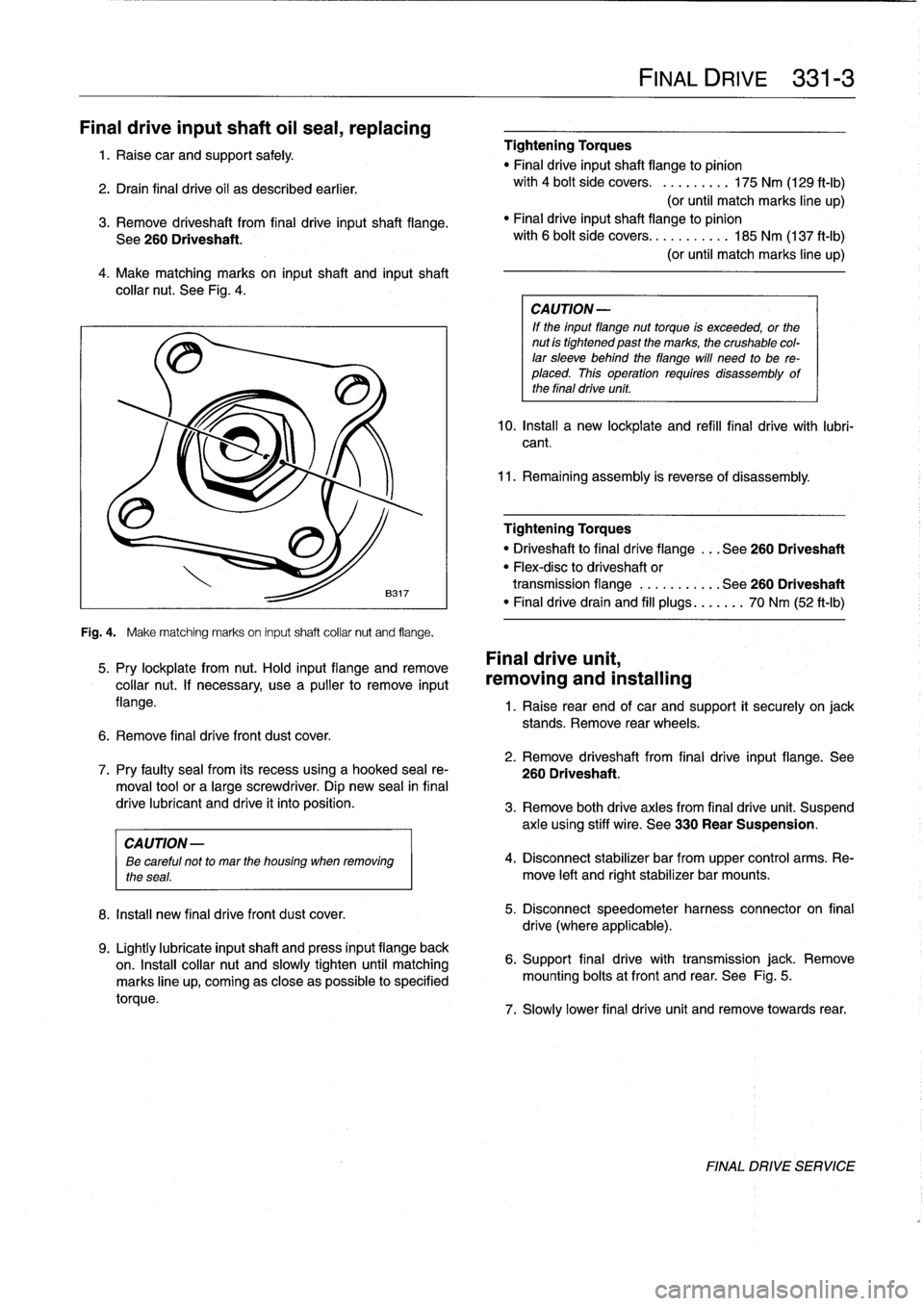
4
.
Make
matching
marks
on
input
shaft
and
inputshaft
collar
nut
.
See
Fig
.
4
.
Fig
.
4
.
Make
matching
marks
on
input
shaft
collar
nut
and
flange
.
5
.
Pry
lockplate
from
nut
.
Hold
input
flange
andremove
collar
nut
.
If
necessary,
usea
pullerto
remove
input
flange
.
6
.
Remove
final
drive
front
dust
cover
.
8
.
Install
new
final
drivefront
dust
cover
.
9
.
Lightly
lubricate
inputshaft
and
press
input
flange
back
on
.
Insta¡¡
collar
nut
and
slowly
tighten
until
matching
marks
line
up,
coming
as
close
aspossible
to
specified
torque
.
Tightening
Torques
"
Final
driveinputshaft
flange
to
pinion
with
4
bolt
side
covers
.
.........
175
Nm
(129
ft-Ib)
(or
until
match
marks
line
up)
"
Finaldriveinputshaft
flange
to
pinion
with
6
bolt
side
covers
...........
185
Nm
(137
ft-Ib)
(or
until
match
marks
line
up)
CA
UTION-
If
the
input
flange
nuttorque
is
exceeded,
or
the
nut
is
tightened
past
the
marks,
the
crushable
col-
lar
sleeve
behind
theflange
will
need
to
be
re-
placed
.
This
operation
requires
disassembly
of
the
final
drive
unit
.
10
.
Install
a
new
lockplate
and
refill
final
drive
with
lubri-
cant
.
11
.
Remaining
assembly
is
reverse
of
disassembly
.
Tightening
Torques
"
Driveshaftto
final
dríve
flange
...
See260
Driveshaft
"
Flex-disc
to
driveshaft
or
transmission
flange
...........
See260
Driveshaft
"
Finaldrivedrain
and
fill
plugs
...
.
..
.
70
Nm
(52
ft-Ib)
Final
drive
unit,
removing
and
installing
FINAL
DRIVE
331-
3
1
.
Raise
rear
end
of
car
and
support
it
securely
on
jack
stands
.
Remove
rear
wheels
.
2
.
Remove
driveshaft
from
final
drive
input
flange
.
See
7
.
Pry
faulty
sea¡
from
its
recess
using
a
hooked
sea¡
re-
260
Driveshaft
.
moval
toolor
a
large
screwdriver
.
Dip
new
sea¡
in
final
drive
lubricant
and
drive
it
into
position
.
3
.
Remove
both
drive
axles
from
final
drive
unit
.
Suspend
axle
using
stiff
wire
.
See
330
Rear
Suspension
.
CAUTION
-
ee
careful
not
to
mar
the
housing
when
removing
4
.
Disconnect
stabilizer
bar
from
upper
control
arms
.
Re-
the
seas
.
move
left
and
rightstabilizer
bar
mounts
.
5
.
Disconnect
speedometer
harness
connector
on
final
drive
(where
applicable)
.
6
.
Support
final
drive
with
transmission
jack
.
Remove
mounting
bolts
atfront
and
rear
.
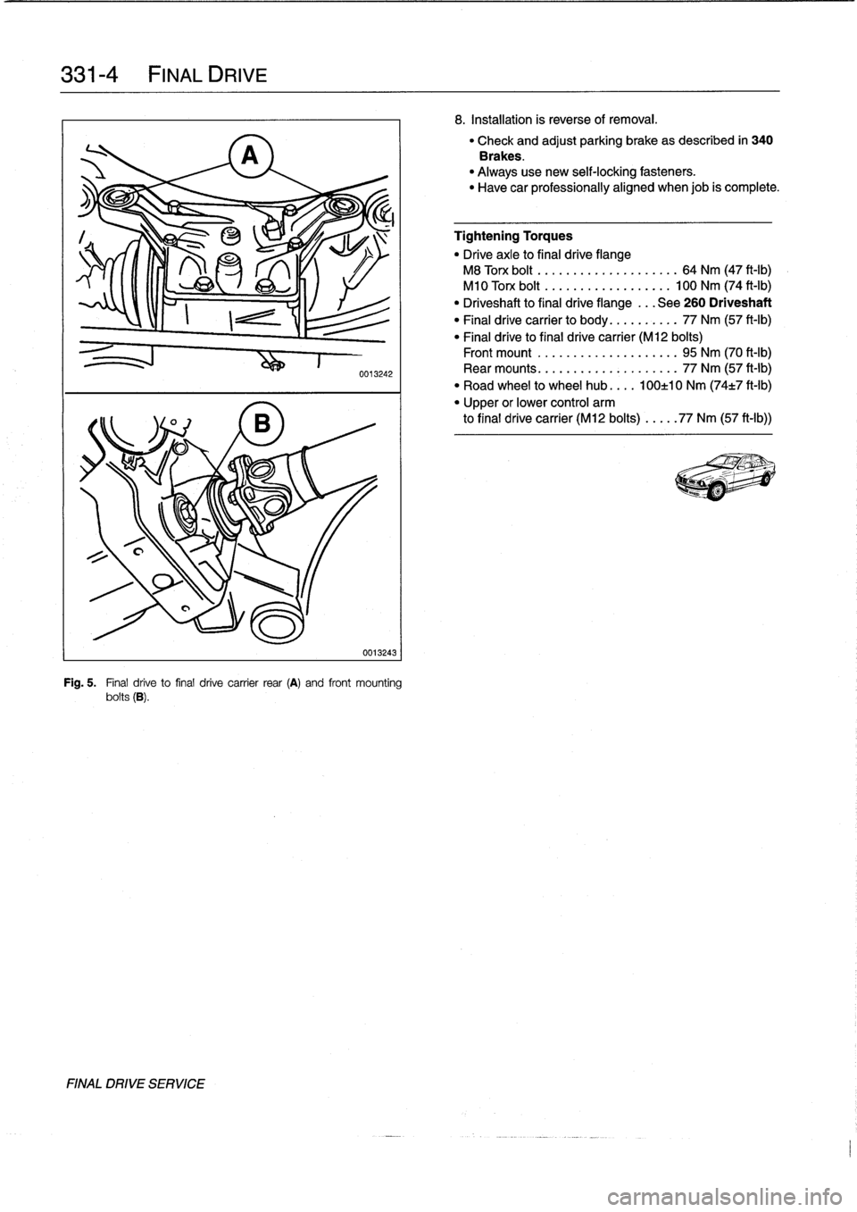
See
Fig
.
5
.
7
.
Slowly
lower
final
drive
unit
and
remove
towards
rear
.
FINAL
DRIVE
SERVICE
Page 290 of 759
331-
4
FINAL
DRIVE
FINAL
DRIVE
SERVICE
0013242
0013243
Fig
.
5
.
Final
drive
to
final
drive
carrier
rear
(A)
and
front
mounting
bolts
(B)
.
8
.
Installation
is
reverse
of
removal
.
"
Check
and
adjust
parking
brake
as
described
in
340
Brakes
.
"
Always
use
new
self-locking
fasteners
.
"
Have
car
professionally
aligned
when
job
is
complete
.
Tightening
Torques
"
Drive
axle
to
final
drive
flange
M8
Torx
bolt
..
.
...
...
..
.........
64
Nm
(47
ft-Ib)
M10
Torx
bolt
.
.
...
...
..
........
100
Nm
(74
ft-Ib)
"
Driveshaft
to
final
drive
flange
...
See
260
Driveshaft
"
Final
drive
carrier
to
body
..
........
77
Nm
(57
ft-Ib)
"
Final
drive
to
final
drive
carrier
(M12
bolts)
Front
mount
.....
...
.
...
........
95
Nm
(70
ft-Ib)
Rear
mounts
.....
.......
.
.
.
..
...
77
Nm
(57
ft-Ib)
"
Road
wheel
to
wheel
hub
....
100±10
Nm
(74±7
ft-Ib)
"
Upper
or
lower
control
arm
to
final
drive
carrier
(M12
bolts)
...
..
77
Nm
(57
ft-Ib))
Page 293 of 759
When
bleeding
the
brakes,
startat
the
wheel
farthest
from
4
.
Close
bleeder
screw
and
release
brake
pedal
.
Refill
the
master
cylinder
and
progress
in
the
following
order
:
brake
fluid
reservoir
and
proceed
to
rear
left
wheel
.
"
right
rear
brake
5
.
Proceed
with
the
remaining
wheels
using
the
order
list-
"
left
rear
brake
ed
earlier
.
"
rightfront
brake
"
left
front
brake
Pressure
bleeding
brakes
(except
carswith
AST)
1
.
Top
off
brake
fluid
in
reservoir
and
connect
pressure
bleeder
to
reservoir
.
Connect
bleeder
hose
and
bottle
to
right
rearcaliper
bleeder
screw
.
Pressurize
system
to
approximately
1
bar
(14
.5
psi)
.
BRAKES
340-
3
Tightening
Torques
"
Bleeder
screws
:
7
mm
screw
..........
..
.
.
.
.
......
5
Nm
(4
ft-Ib)
9
mm
screw
..........
..
.
..
.......
6
Nm
(5
ft-Ib)
BRAKE
PADS,
CALIPERS,
AND
ROTORS
CAUTION-
TheE36
front
brake
caliper
is
shown
in
Fig
.
2
.
The
rear
Do
not
exceed
a
pressure
of
2
bar
(29
psi)
when
brake
caliper
is
shown
in
Fig
.
7
.
pressure
bleeding
the
brake
system
.
Excessive
pressure
will
damage
the
brake
fluid
reservoir
.
Brake
pads
canbe
replaced
without
disconnecting
the
brake
fluid
hose
from
the
caliper
or
having
to
bleed
the
brakes
.
2
.
Have
a
helperhold
brake
pedal
down
.
The
rotors
can
be
replaced
without
disassembling
the
wheel
huband
bearing
.
Always
machine
or
replace
rotors
in
parts
.
3
.
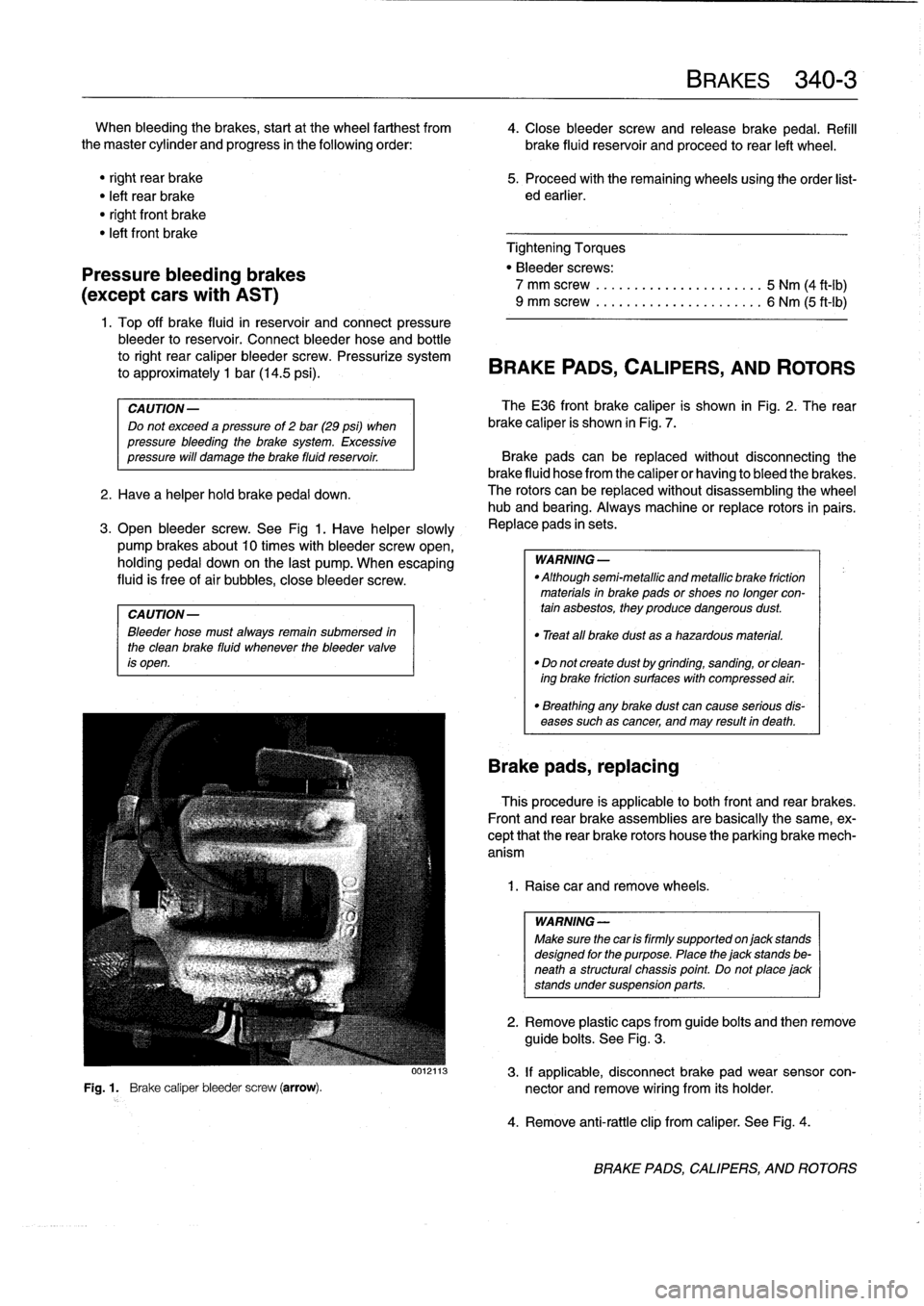
Open
bleeder
screw
.
See
Fig
1
.
Have
helper
slowly
,
Replace
pads
in
sets
.
pump
brakes
about10
times
with
bleeder
screw
open,
holding
pedal
down
on
the
last
pump
.
When
escaping
WARNING-
fluid
is
free
of
air
bubbles,
close
bleeder
screw
.
"
Althoughsemi-metallicandmetallicbrake
friction
materials
in
brake
pads
or
shoes
no
longer
con
CAUTION-
tain
asbestos,
they
produce
dangerous
dust
.
Bleeder
hose
must
alwaysremain
submersed
in
"
Treat
all
brake
dust
asa
hazardous
material
.
the
clean
brake
fluid
whenever
the
bleeder
valve
is
open
.
"
Do
not
create
dust
by
grinding,
sanding,
orclean-
ing
brake
friction
surfaces
with
compressed
air
.
"
Breathing
any
brake
dust
can
cause
serious
dis-
eases
such
as
cancer,
and
may
result
in
death
.
Brake
pads,
replacing
This
procedure
is
applicable
lo
both
front
and
rear
brakes
.
Front
and
rear
brake
assemblies
are
basically
the
same,
ex-
cept
that
the
rear
brake
rotors
house
the
parking
brake
mech-
anism
1
.
Raise
car
andremove
wheels
.
WARNING
-
Make
sure
thecar
is
firmly
supported
onjack
stands
designed
for
the
purpose
.
Place
the
jack
stands
be-
neath
a
structural
chassis
point
.
Do
not
place
jack
stands
undersuspension
parts
.
2
.
Remove
plastic
caps
from
guide
bolts
and
then
remove
guide
bolts
.
See
Fig
.
3
.
0012113
3
.
If
applicable,
disconnect
brake
pad
wear
sensor
con-
Fig
.
1
.
Brake
caliper
bleeder
screw
(arrow)
.
nector
and
remove
wiring
from
its
holder
.
4
.
Remove
anti-rattle
clip
from
caliper
.
See
Fig
.
4
.
BRAKE
PADS,
CALIPERS,
AND
ROTORS