tow BMW 328i 1998 E36 Owner's Guide
[x] Cancel search | Manufacturer: BMW, Model Year: 1998, Model line: 328i, Model: BMW 328i 1998 E36Pages: 759
Page 237 of 759
2
.
Install
rubber
grommet
with
arrow
pointing
forward
.
In-
AUTOMATic
TRANSMISSION
stall
shift
rod
and
shift
boot
.
GEARSHIFT
NOTE-
Install
rubbergrommet
correctly
so
that
is
seals
outwa-
ter
.
4
.
Install
driveshaft
and
heat
shield
.
See
260
Driveshaft
.
Manual
valveleven
(at
transmission)
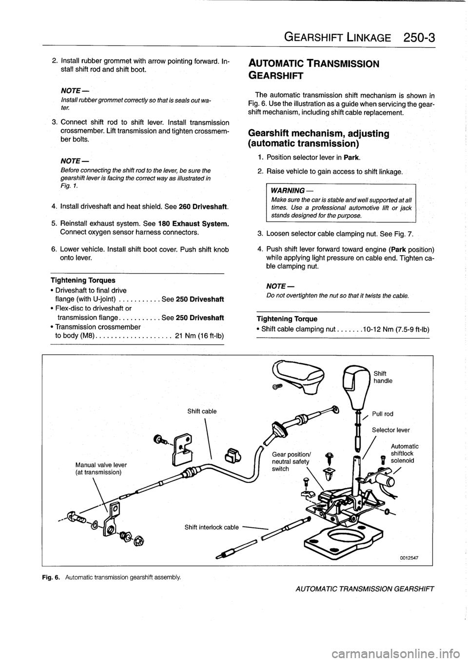
Fig
.
6
.
Automatic
transmission
gearshift
assembfy
.
Shift
cable
GEARSHIFT
LINKAGE
250-
3
The
automatic
transmission
shift
mechanism
is
shown
in
Fig
.
6
.
Use
the
illustration
as
a
guide
when
servícing
the
gear-
shift
mechanism,
including
shift
cable
replacement
.
3
.
Connect
shift
rod
to
shift
lever
.
Install
transmission
crossmember
.
Lift
transmission
and
tighten
crossmem-
Gearshift
mechanism,
adjusting
ber
bolts
.
(automatictransmission)
NOTE-
1
.
Position
selector
lever
in
Park
.
Beforeconnecting
the
shift
rod
to
the
lever,
be
sure
the
2
.
Raise
vehicle
to
gain
access
to
shift
linkage
.
gearshift
leven
is
facing
the
correct
way
as
illustrated
in
Fig
.
1
.
WARNING
-
Make
sure
thecan
is
stable
and
well
supported
at
all
times
.
Use
a
professional
automotive
lift
or
jack
stands
designed
for
the
purpose
.
5
.
Reinstall
exhaust
system
.
See
180
Exhaust
System
.
Connect
oxygen
sensor
harness
connectors
.
3
.
Loosen
selector
cable
clamping
nut
.
See
Fig
.
7
.
6
.
Lower
vehicle
.
Insta¡¡
shift
boot
cover
.
Push
shift
knob
4
.
Push
shift
lever
forwardtoward
engine(Park
position)
onto
lever
.
while
applying
light
pressure
on
cable
end
.
Tighten
ca-
ble
clamping
nut
.
Tightening
Torques
NOTE-
"
Driveshaft
to
final
drive
Do
not
overtighten
the
nut
so
that
it
twists
the
cable
.
flange
(with
U-joint)
.
..
.
.....
.
.
See
250
Driveshaft
"
Flex-disc
to
driveshaft
or
transmission
flange
...
.
.......
See
250
Driveshaft
Tightening
Torque
"
Transmission
crossmember
"
Shift
cable
clamping
nut
.......
10-12
Nm
(75-9
ft-Ib)
to
body
(M8)
.
.
.
...
..............
21
Nm
(16
ft-Ib)
/S
r\
1
1
Gear
position/
neutral
safetyswitch
Automatic
shilo
solenoid
id
AUTOMATIC
TRANSMISSION
GEARSHIFT
Page 245 of 759
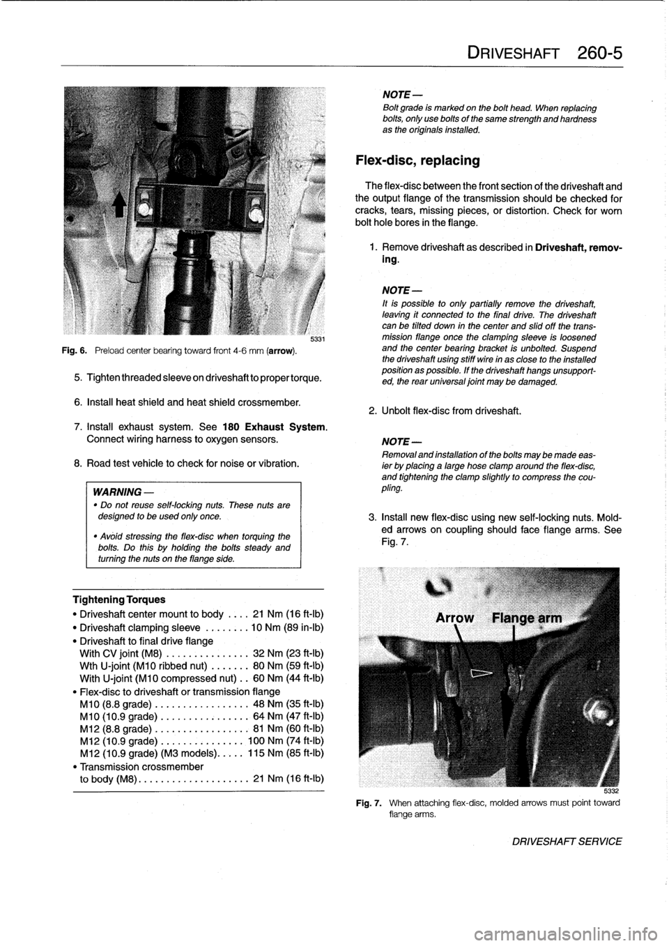
Fig
.
6
.
Preload
center
bearing
toward
front
4-6
mm
(arrow)
.
5331
5
.
Tightenthreadedsleeveondriveshafttopropertorque
.
6
.
Insta¡¡
heat
shield
and
heat
shield
crossmember
.
Tightening
Torques
"
Driveshaftcenter
mount
to
body
.
.
..
21
Nm
(16
ft-Ib)
"
Driveshaft
clamping
sleeve
.....
.
.
.
10
Nm
(89
in-lb)
"
Driveshaft
to
final
drive
flange
With
CV
joint
(M8)
............
...
32
Nm
(23
ft-Ib)
Wth
U-joint
(M10
ribbed
nut)
....
...
80
Nm
(59
ft-Ib)
With
U-joint
(M10
compressed
nut)
..
60
Nm
(44
ft-Ib)
"
Flex-disc
to
driveshaft
or
transmissionflange
M10
(8.8
grade)
.........
.
....
..
.
48
Nm
(35
ft-Ib)
M10
(10
.9
grade)
........
.
....
...
64
Nm
(47
ft-Ib)
M12
(8.8
grade)
........
.....
..
.
.
81
Nm
(60
ft-Ib)
M12
(10
.9
grade)
.
.
....
......
...
100
Nm
(74
ft-Ib)
M12
(10
.9
grade)
(M3
models)
..
.
.
.
115
Nm
(85
ft-Ib)
"
Transmission
crossmember
to
body
(M8)
.
....
...........
....
21
Nm
(16
ft-Ib)
NOTE-
Bolt
grade
is
markedon
the
bolt
head
.
When
replacing
bolts,
only
use
bolts
of
the
same
strength
and
hardnessas
the
originalsinstalled
.
Flex-disc,
replacing
The
flex-disc
between
the
front
section
of
the
driveshaft
and
theoutputflange
of
the
transmission
should
be
checked
for
cracks,
tears,
missing
pieces,
or
distortion
.
Check
for
worn
bolt
hole
bores
in
theflange
.
1
.
Remove
driveshaft
as
described
in
Driveshaft,
remov-
ing
.
NOTE-
¡t
is
possible
to
only
partially
remove
the
driveshaft,
leaving
it
connected
to
the
final
drive
.
The
driveshaft
canbe
tilted
down
in
thecenter
and
slidoff
the
trans-
mission
flange
once
the
clamping
sleeve
is
loosened
and
the
center
bearing
bracket
is
unbolted
.
Suspend
the
driveshaft
using
stiff
wire
in
as
close
to
the
installed
position
as
possible
.
If
the
driveshaft
hangs
unsupport-
ed,
the
rear
universal
joint
may
be
damaged
.
2
.
Unbolt
flex-dísc
from
driveshaft
.
DRIVESHAFT
260-
5
7
.
Install
exhaust
system
.
See
180
Exhaust
System
.
Connect
wiring
harness
to
oxygen
sensors
.
NOTE-
Removaland
installation
of
the
boltsmaybe
made
eas-
8
.
Road
test
vehicle
to
check
for
noiseor
vibration
.
ier
by
placing
a
large
hose
clamp
around
the
flex-disc,
and
tightening
the
clamp
slightlyto
compress
the
cou
WARNING
-
pling
.
"
Do
not
reuse
self-locking
nuts
.
These
nuts
aredesigned
to
beused
only
once
.
3
.
Insta¡¡
new
flex-disc
using
new
self-locking
nuts
.
Mold-
"
Avóid
stressing
the
flex-disc
when
torquing
the
ed
arrows
on
coupling
should
face
flange
arms
.
See
bolts
Do
this
holding
the
bolts
Fig
.
7
.
steady
and
.
uy
turning
the
nuts
on
theflange
side
.
5
:132
Fig
.
7
.
When
attaching
flex-disc,
molded
arrows
must
point
toward
flange
arms
.
DRIVESHAFT
SERVICE
Page 255 of 759
increased
power
output
and
road-handling
demands
.
The
steering
geometry
is
modified
by
changing
the
cast-
er/camber
angles
slightly
.
This
is
accomplishedby
reposition-
ing
the
upper
strut
mounting
holes
in
the
frontstrut
towers
and
through
different
front
and
rear
control
arms
.
M3
Brake
System
Improvements
"
Vented
directionalfront
rotors
:
315
mm
dia
.
x
28
mm
thick
.
"
Vented
directional
rear
rotors
:
312
mm
dia
.
x20
mm
thick
.
"
Larger
brake
pads
and
calipers
.
"
Modified
Teves
ABS
system
.
SUSPENSION,
STEERING
AND
BRAKES-GENERAL
300-
7
M3
SUSPENSION
AND
BRAKES
NOTE-
M3
brake
rotors
are
directional,
having
a
different
part
TheE36
M3
was
introduced
in
late
1994
as
a
1995
model
.
number
for
each
side
.
Rotors
with
an
odd
part
number
The
design
of
the
M3
suspension,
steering
and
brakes
is
a
go
on
the
left
while
rotors
with
en
even
part
numbergo
modification
of
existing
E36
systems
which
accommodates
on
the
right
.
M3
Front
SuspensionImprovements
"
Reinforced
spring
plates,control
arms,
control
arm
bush-
ings,
steering
arms
.
"
Recalibrated
struts,
firmer
springs
.
"
Stiffer
stabilizerbar,
larger
stabilizer
bar
bushings
.
"
Front
stabilizer
linked
to
struts
.
M3
Wheels/Tires
"
Front
wheels
1992-1998
:.....
7
.5J
x
17
in
.
light
alloy
"
Rear
wheel
1992-1997
.......
7
.5J
x17
in
.
light
alloy
"
Rear
wheel
(option)
........
.8
.5
Jx17
in
.
light
alloy
"
Front
and
rear
tire
1992-1997
.............
.
.
.
...
...
235/40
x
17
in
.
"
Front
tire
1998
only
......
...
.
.
.
...
225/45
x
17
in
.
"
Rear
tire
1998
only
.......
.
.
.
...
...
245/40
x
17
in
.
CAUTION-
In
en
emergency,
an
M3
front
wheel/tire
assembly
may
be
mounted
on
the
rearaxle
.
However
a
rear
wheel/tire
assemblymust
not
be
mounted
on
the
front
axle
.
M3
RearSuspensionImprovements
"
Reinforced
trailing
arms
.
"
Recalibrated
shock
absorbers,
firmer
springs
.
SUSPENSION
AND
STEERING
TROUBLESHOOTING
Stable
handling
and
ride
comfort
both
depend
on
the
integ-
rity
of
the
suspension
and
steering
components
.
Any
symp-
tom
of
instability
or
imprecise
road
feel
may
be
caused
by
worn
or
damaged
suspension
components
.
When
troubleshooting
suspension
and
steering
problems,
also
consider
the
condition
of
tires,
wheels,
and
their
align-
ment
.
Tire
wear
and
incorrect
inflation
pressures
can
dramati-
cally
affect
handling
.
Subtie
irregularities
in
wheel
alignment
angles
also
affect
stabílity
.
Mixing
different
types
or
sizes
of
tires,
particularly
on
the
same
axle,
can
affect
alignment
and
may
unbalancea
car's
handling
.
Table
b
lists
the
symptoms
of
common
suspension
and
steering
problems
and
their
probable
causes,
and
suggests
corrective
actions
.
Bold
type
indicates
the
repair
groups
where
applicable
test
and
repair
procedures
can
befound
.
SUSPENSION
AND
STEERING
TROUBLESHOOTING
Page 259 of 759
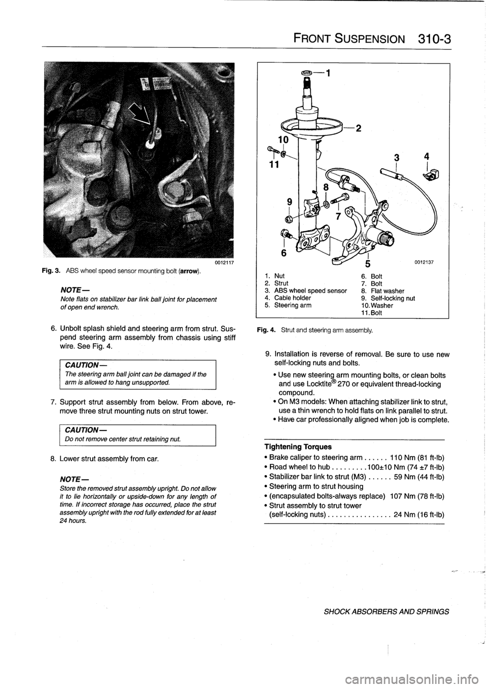
Fig
.
3
.
ABS
wheel
speed
sensor
mounting
bolt
(arrow)
.
NOTE-
Note
flats
on
stabilizer
bar
linkball
joint
for
placement
of
open
end
wrench
.
CAUTION-
Do
not
remove
center
strut
retaining
nut
.
8
.
Lower
strut
assembly
from
car
.
NOTE-
Store
the
removed
strut
assembly
upríght
.
Do
not
allow
it
to
líe
horizontally
or
upside-down
for
any
lengthoftime
.
If
íncorrect
storage
has
occurred,
place
the
strut
assembly
upríght
wíth
the
rod
fully
extended
for
at
least
24
hours
.
0012117
FRONT
SUSPENSION
310-3
6
.
Unbolt
splash
shield
and
steering
arm
from
strut
.
Sus-
Fig
.
4
.
Strut
and
steering
arm
assembly
.
pend
steering
arm
assembly
from
chassis
using
stiff
wire
.
See
Fig
.
4
.
1
.
Nut
6
.
Bolt
2
.
Strut
7
.
Bolt
3
.
ABS
wheel
speed
sensor
8
.
Flat
washer
4
.
Cable
holder
9
.
Self-locking
nut
5
.
Steering
arm
10
.
Washer
11
.
Bolt
9
.
Installation
is
reverse
of
removal
.
Be
sure
to
use
new
CAUTION-
self-locking
nuts
and
bolts
.
The
steering
arm
ball
joint
can
be
damaged
if
the
"
Use
new
steering
arm
mounting
bolts,
or
clean
bolts
arm
is
allowed
to
hang
unsupported
.
and
use
Locktite
®
270
orequivalent
thread-locking
compound
.
7
.
Support
strut
assembly
from
below
.
From
above,
re-
"
On
M3
models
:
When
attaching
stabilizer
link
to
strut,
move
three
strut
mounting
nuts
on
strut
tower
.
use
a
thin
wrench
to
hold
flats
on
link
parallelto
strut
.
"
Have
car
professionally
aligned
When
job
is
complete
.
Tightening
Torques
"
Brake
caliper
to
steering
arm
......
110
Nm
(81
ft-lb)
"
Road
wheel
to
hub
.........
100±10
Nm
(74
t7
ft-Ib)
"
Stabilizer
bar
link
to
strut
(M3)
.....
.
59
Nm
(44
ft-lb)
"
Steering
arm
to
strut
housing
"
(encapsulated
bolts-always
replace)
107
Nm
(78
ft-lb)
"
Strut
assembly
to
strut
tower
(self-locking
nuts)
........
...
..
..
.
24
Nm
(16
ft-Ib)
SHOCK
ABSORBERS
AND
SPRINGS
Page 263 of 759
6
.
Installation
is
reverse
of
removal
.
"
Make
sure
control
arm
ball
joint
taper
bore
is
clean
and
free
of
any
corrosion
.
"
Press
new
balljoint
into
position,
making
sure
to
align
balljoint
guide
with
mark
made
earlier
.
"
Verify
that
locking
clip
on
new
ball
joint
faces
towards
center
of
vehicle
.
Tightening
Torques
"
Control
arm
ball
jointto
steering
arm
.
65
Nm
(48
ft-Ib)
"
Stabilizer
bar
link
to
control
arm
(M8)
42
Nm
(31
ft-Ib)
"
Road
wheel
to
hub
.
...
...
.
.
100±10
Nm
(74t7
ft-lb)
Control
arm
bushing,
replacing
Control
arm
bushings
should
aiways
be
replaced
in
pairs
and
the
two
bushings
and
bushing
carriers
should
have
the
same
markings,
indicating
same
manufacturer
.
1
.
Raisecar
.
WARNING-
Make
sure
that
the
car
is
firmly
supportedonjackstandsdesigned
for
the
purpose
.
Place
the
jackstands
beneath
a
structural
chassis
point
.
Do
not
place
jack
stands
undersuspension
parts
.
2
.
Unbolt
control
arm
bushing
carrier
from
body
.
3
.
Mark
installed
position
of
bushing
to
control
arm
.
See
Fig
.
11
.
assembly
off
control
arm
.
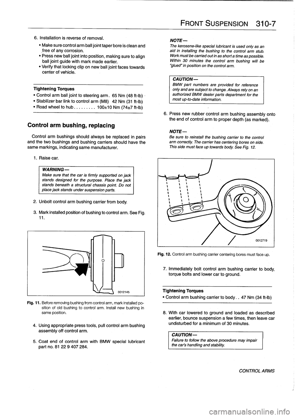
lnl~
0012145
FRONT
SUSPENSION
310-
7
NOTE-
The
kerosene-like
special
lubricant
is
used
only
asan
aid
in
installing
the
bushing
to
the
control
arm
stub
.
Workmustbe
carried
out
in
as
short
a
time
as
possible
.
Within
30
minutes
the
control
arm
bushing
will
be
`glued"
in
position
on
the
control
arm
.
CAUTION-
BMW
part
numbers
areprovided
for
reference
only
and
are
subject
to
change
.
Always
rely
on
an
authorized
BMW
dealerparts
department
for
the
most
up-to-date
information
.
6
.
Press
new
rubber
control
arm
bushing
assembly
onto
the
end
of
control
arm
to
proper
depth
(as
marked)
.
NOTE-
Be
sure
toreinstall
the
bushing
carrier
to
the
control
arm
correctly
.
The
carrier
has
centering
bores
on
side
.
This
side
must
face
up
towards
body
.
See
Fig
.
12
.
Fig
.
12
.
Control
arm
bushing
carrier
centering
bores
must
face
up
.
7
.
Immediately
bolt
control
arm
bushing
carrier
to
body,
torque
boits
and
lower
car
to
ground
.
Tightening
Torques
"
Control
arm
bushing
carrier
to
body
.
.
47
Nm
(34
ft-ib)
Fig
.
11
.
Before
removingbushing
from
control
arm,
mark
installed
po-
sition
of
old
bushing
to
control
arm
.
Insta¡¡
new
bushing
in
same
position
.
8
.
With
car
lowered
to
ground
and
loaded
as
described
earlier,
bounce
suspensiona
few
times,
then
leave
car
4
.
Using
appropriate
press
tools,
pull
control
arm
bushing
undisturbed
for
a
minimum
of
30
minutes
.
CAUTION-
5
.
Coat
end
of
control
arm
with
BMW
special
lubricant
I
Failure
to
follow
the
above
procedure
may
impair
part
no
.
8122
9
407284
.
the
car's
handling
and
stability
.
CONTROLARMS
Page 276 of 759
330-
4
REAR
SUSPENSION
7
.
Installation
is
reverse
ofremoval,
noting
the
following
:
"
Make
sure
all
threaded
bolts,
nuts
and
makng
surfaces
are
clean
.
"
Instan
shock
absorber
finto
shock
tower
using
a
new
uppermounting
gasket
and
new
self-locking
nuts
.
"
Tighten
lower
boltto
its
final
torque
oncecar
is
on
ground
.
Tightening
Torques
"
Road
wheel
to
hub
.........
100±10
Nm
(74±7
ft-Ib)
"
Shock
absorber
to
trailing
arm
(car
in
normalloaded
position)
......
77
Nm
(57
ft-Ib)
"
Shock
absorber
to
upper
mount
.....
14
Nm
(10
ft-Ib)
"
Shock
absorber
upper
mount
to
body
(M8
self-locking
nuts)
.............
24
Nm
(17
ft-Ib)
Coil
spring,
removing
and
installing
WARNING
-
"
The
coil
spring
is
undercompressive
force
and
ís
extremely
dangerous
until
compression
isre-
moved
.
"
lt
is
recommended
that
a
restraining
chain
be
in-
stalled
between
the
bottomof
the
coil
spring
and
the
upper
control
arm
to
retain
the
spring
in
case
of
accidental
release
.
Personal
injury
can
result
if
the
compressed
coil
spring
is
not
released
slowly
and
carefully
.
"
Make
sure
that
the
car
is
firmly
supported
on
jack
standsdesigned
for
the
purpose
.
Place
the
jack
standsbeneatha
structural
chassis
point
.
Do
not
place
jack
stands
under
suspension
parts
.
1
.
Raise
car
and
remove
rear
wheel
.
2
.
Support
suspension
arm
from
below
using
a
transmis-
sion
jack
orequívalent
.
Tightening
Torques
3
.
Remove
drive
axle
from
final
drive
.
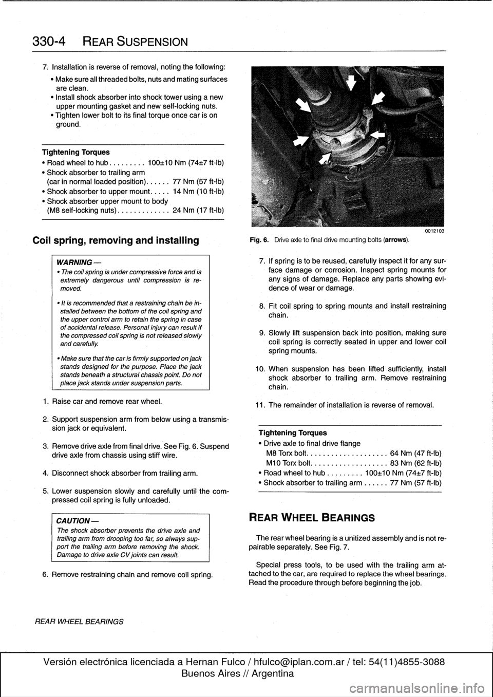
See
Fig
.
6
.
Suspend
"
Drive
axle
to
final
drive
flange
drive
axle
from
chassis
using
stiff
wire
.
M8
Torx
bolt
.
..
...
.
.............
64
Nm
(47
ft-Ib)
M10
Torx
bolt
...................
83
Nm
(62
ft-Ib)
4
.
Disconnect
shock
absorber
from
traíling
arm
.
"
Road
wheel
to
hub
.........
100±10
Nm
(74±7
ft-Ib)
"
Shock
absorber
to
trailing
arm
......
77
Nm
(57
ft-Ib)
5
.
Lower
suspension
slowly
and
carefully
until
the
com-
pressed
coil
spring
is
fully
unloaded
.
CAUTION
-
The
shock
absorber
prevents
the
drive
axle
and
trailíng
arm
from
drooping
too
far,
so
always
sup-port
the
trailing
arm
before
removing
the
shock
.
Damage
to
drive
axle
CV
joints
can
result
.
6
.
Remove
restraining
chain
and
remove
coi¡
spring
.
REAR
WHEEL
BEARINGS
Fig
.
6
.
Driveaxle
to
final
drive
mounting
bolts
(arrows)
.
0012103
7
.
If
spring
is
to
be
reused,
carefully
inspect
it
for
any
sur-
face
damage
or
corrosion
.
Inspect
spring
mounts
for
any
signs
of
damage
.
Replace
any
parts
showing
evi-
dence
of
wear
or
damage
.
8
.
Fit
coil
springtospring
mountsand
insta¡¡
restraíning
chaina
9
.
Slowly
lift
suspensionback
into
position,
making
sure
coil
spring
is
correctly
seated
in
upper
and
lower
coil
spring
mounts
.
10
.
When
suspension
has
been
lifted
sufficiently,
instan
shock
absorber
to
trailing
arm
.
Remove
restraining
chain
.
11
.
The
remainder
of
installation
is
reverse
of
removal
.
REAR
WHEEL
BEARINGS
The
rear
wheel
bearing
is
a
unitized
assembly
and
is
not
re-
pairable
separately
.
See
Fig
.
7
.
Special
press
tools,
to
be
used
with
the
trailing
arm
at-
tached
to
the
car,
are
requiredto
replace
the
wheel
bearings
.
Read
the
procedure
through
before
beginning
thejob
.
Page 289 of 759
Final
driveinputshaft
oil
sea¡,
replacing
1
.
Raise
car
and
support
safely
.
2
.
Drain
final
drive
oil
as
described
earlier
.
3
.
Remove
driveshaft
from
final
drive
inputshaft
flange
.
See
260
Driveshaft
.
4
.
Make
matching
marks
on
input
shaft
and
inputshaft
collar
nut
.
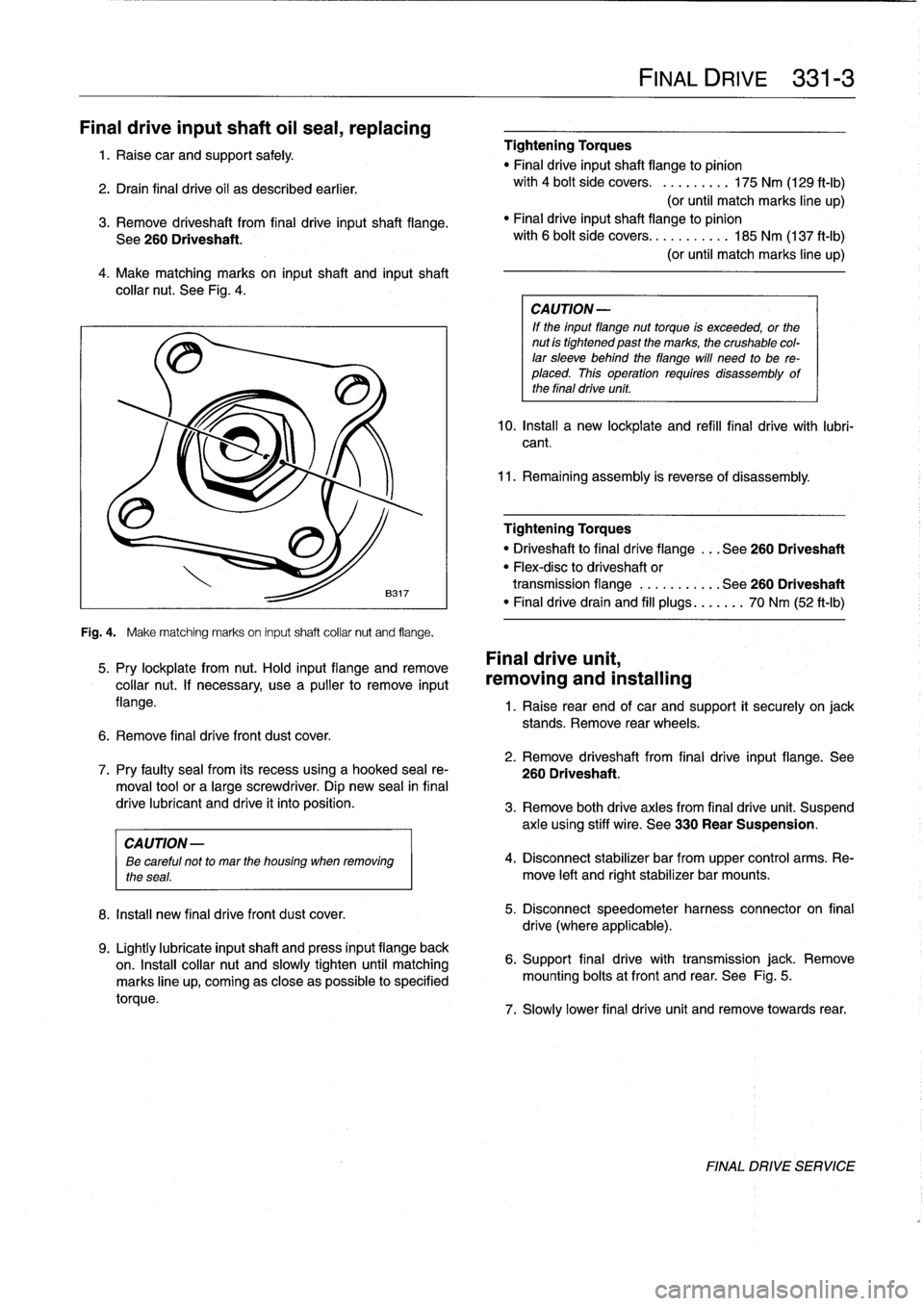
See
Fig
.
4
.
Fig
.
4
.
Make
matching
marks
on
input
shaft
collar
nut
and
flange
.
5
.
Pry
lockplate
from
nut
.
Hold
input
flange
andremove
collar
nut
.
If
necessary,
usea
pullerto
remove
input
flange
.
6
.
Remove
final
drive
front
dust
cover
.
8
.
Install
new
final
drivefront
dust
cover
.
9
.
Lightly
lubricate
inputshaft
and
press
input
flange
back
on
.
Insta¡¡
collar
nut
and
slowly
tighten
until
matching
marks
line
up,
coming
as
close
aspossible
to
specified
torque
.
Tightening
Torques
"
Final
driveinputshaft
flange
to
pinion
with
4
bolt
side
covers
.
.........
175
Nm
(129
ft-Ib)
(or
until
match
marks
line
up)
"
Finaldriveinputshaft
flange
to
pinion
with
6
bolt
side
covers
...........
185
Nm
(137
ft-Ib)
(or
until
match
marks
line
up)
CA
UTION-
If
the
input
flange
nuttorque
is
exceeded,
or
the
nut
is
tightened
past
the
marks,
the
crushable
col-
lar
sleeve
behind
theflange
will
need
to
be
re-
placed
.
This
operation
requires
disassembly
of
the
final
drive
unit
.
10
.
Install
a
new
lockplate
and
refill
final
drive
with
lubri-
cant
.
11
.
Remaining
assembly
is
reverse
of
disassembly
.
Tightening
Torques
"
Driveshaftto
final
dríve
flange
...
See260
Driveshaft
"
Flex-disc
to
driveshaft
or
transmission
flange
...........
See260
Driveshaft
"
Finaldrivedrain
and
fill
plugs
...
.
..
.
70
Nm
(52
ft-Ib)
Final
drive
unit,
removing
and
installing
FINAL
DRIVE
331-
3
1
.
Raise
rear
end
of
car
and
support
it
securely
on
jack
stands
.
Remove
rear
wheels
.
2
.
Remove
driveshaft
from
final
drive
input
flange
.
See
7
.
Pry
faulty
sea¡
from
its
recess
using
a
hooked
sea¡
re-
260
Driveshaft
.
moval
toolor
a
large
screwdriver
.
Dip
new
sea¡
in
final
drive
lubricant
and
drive
it
into
position
.
3
.
Remove
both
drive
axles
from
final
drive
unit
.
Suspend
axle
using
stiff
wire
.
See
330
Rear
Suspension
.
CAUTION
-
ee
careful
not
to
mar
the
housing
when
removing
4
.
Disconnect
stabilizer
bar
from
upper
control
arms
.
Re-
the
seas
.
move
left
and
rightstabilizer
bar
mounts
.
5
.
Disconnect
speedometer
harness
connector
on
final
drive
(where
applicable)
.
6
.
Support
final
drive
with
transmission
jack
.
Remove
mounting
bolts
atfront
and
rear
.
See
Fig
.
5
.
7
.
Slowly
lower
final
drive
unit
and
remove
towards
rear
.
FINAL
DRIVE
SERVICE
Page 299 of 759
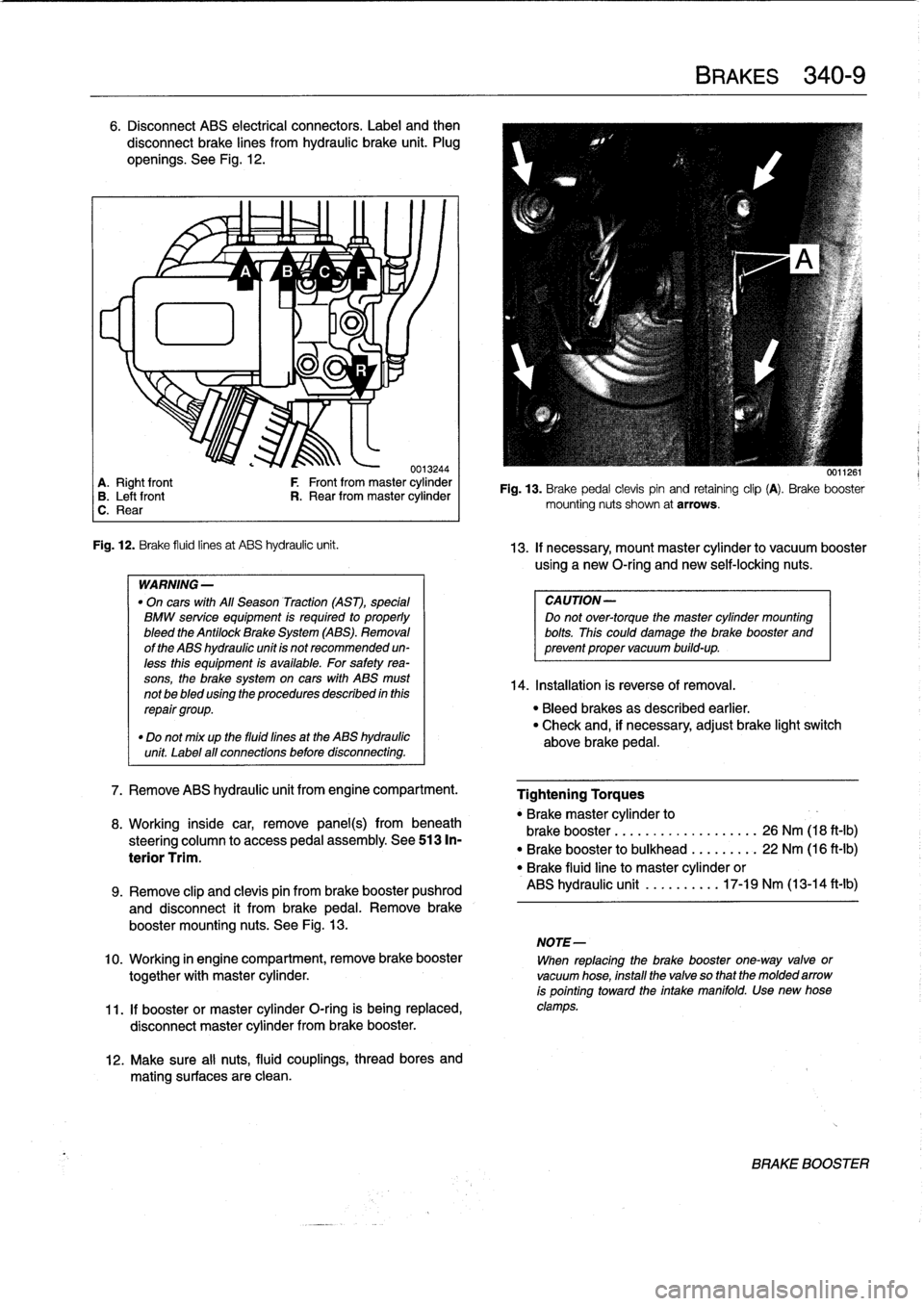
6
.
Disconnect
ABS
electrical
connectors
.
Label
and
then
disconnect
brake
lines
from
hydraulic
brake
unit
.
Plug
openíngs
.
See
Fig
.
12
.
~
~
A
1/
B
'1v
C
~
F
lu
11
-ri
J
.
0013244
A
.
Right
front
F
Front
from
master
cylinder
B
.
Leftfront
R
.
Rear
from
master
cylinder
C
.
Rear
Fig
.
12
.
Brake
fluid
linesat
ABS
hydraulic
unit
.
WARNING
-
"
On
cars
with
All
Season
Traction
(AST),
special
BMW
service
equipment
is
required
to
properly
bleed
the
Antilock
Brake
System
(ABS)
.
Removal
of
the
ABS
hydraulic
unit
is
not
recommended
un-
less
this
equipment
is
available
.
For
safetyrea-
sons,
the
brake
system
on
cars
with
ABS
must
not
be
bled
using
the
procedures
described
inthis
repair
group
.
"
Do
not
mix
up
the
fluid
fines
at
the
ABS
hydraulic
unit
Label
all
connections
before
disconnecting
.
7
.
Remove
ABS
hydraulic
unit
from
engine
compartment
.
8
.
Working
inside
car,
remove
panel(s)
frombeneath
steering
column
to
access
pedal
assembly
.
See513
In-
terior
Trim
.
12
.
Make
sure
al¡
nuts,
fluid
couplings,
thread
bores
and
mating
surfaces
are
clean
.
BRAKES
340-
9
0011261
Fig
.
13
.
Brake
pedal
clevispin
and
retaining
clip
(A)
.
Brake
booster
mounting
nuts
shown
at
arrows
.
13
.
If
necessary,
mount
master
cylinder
to
vacuum
booster
using
a
new
O-ríng
and
newself-locking
nuts
.
CAUTION-
Do
not
over-torque
the
master
cylinder
mounting
bolts
.
This
could
damage
the
brake
booster
and
prevent
proper
vacuum
build-up
.
14
.
Installation
is
reverse
of
Rmoval
.
"
Bleed
brakes
as
described
earlier
.
"
Check
and,
if
necessary,
adjust
brake
light
switch
above
brake
pedal
.
Tightening
Torques
"
Brakemaster
cylinder
to
brake
booster
...........
.
..
..
...
26
Nm
(18
ft-Ib)
"
Brake
booster
to
bulkhead
.
.
..
..
...
22
Nm
(16
ft-Ib)
"
Brake
fluidline
to
master
cylinder
or
ABS
hydraulic
unit
.......
.
..
17-19
Nm
(13-14
ft-lb)
9
.
Remove
clip
and
clevis
pin
from
brake
booster
pushrod
and
disconnect
it
from
brakepedal
.
Remove
brake
booster
mounting
nuts
.
See
Fig
.
13
.
NOTE-
10
.
Working
in
engine
compartment,
remove
brake
booster
When
replacing
the
brake
booster
one-way
valve
or
together
with
master
cylinder
.
vacuum
hose,
install
the
valve
so
that
the
molded
arrow
is
pointing
toward
the
intake
manifold
.
Use
new
hose
11
.
If
booster
or
master
cylinder
O-ring
is
being
replaced,
clamps
.
disconnect
master
cylinder
from
brake
booster
.
BRAKE
BOOSTER
Page 325 of 759
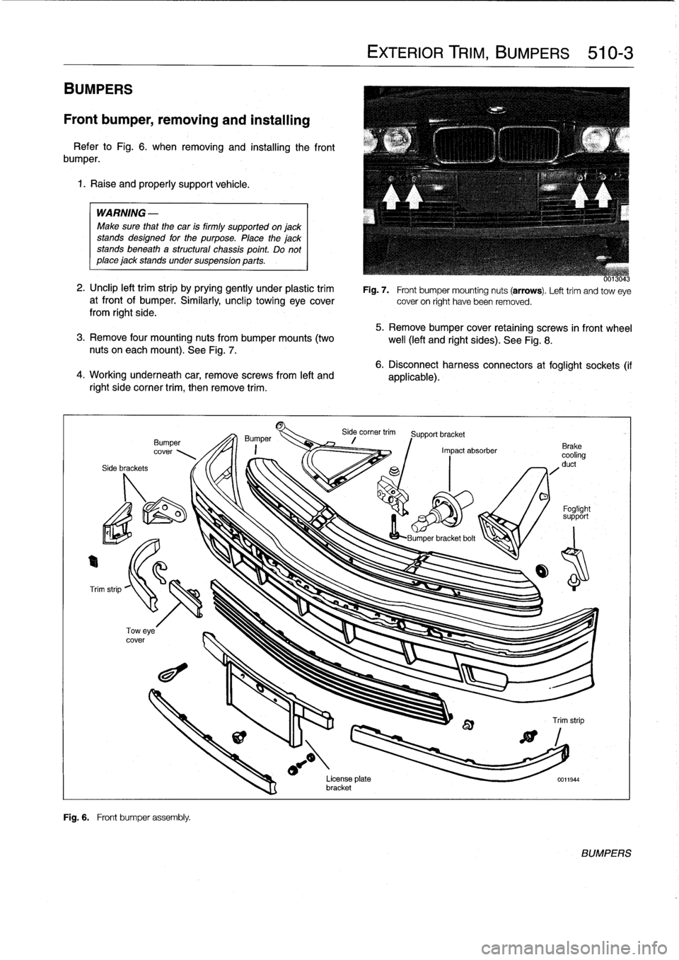
BUMPERS
Front
bumper,
removing
and
installing
Refer
to
Fig
.
6
.
when
removing
and
installing
the
front
bumper
.
1
.
Raise
and
properly
support
vehicle
.
WARNING
-
Make
sure
that
the
car
is
firmly
supportedonjack
stands
designed
for
the
purpose
.
Place
the
jackstands
beneath
a
structural
chassis
point
.
Do
not
place
jack
stands
undersuspension
parts
.
2
.
Unclip
left
trim
strip
by
prying
gently
under
plastic
trim
at
front
of
bumper
.
Similarly,
unclip
towing
eyecoverfrom
right
side
.
5
.
Remove
bumper
cover
retaining
screws
in
front
wheel
3
.
Remove
four
mounting
nuts
from
bumper
mounts
(two
well
(left
and
right
sides)
.
See
Fig
.
8
.
nuts
on
eachmount)
.
See
Fig
.
7
.
4
.
Working
underneath
car,
removescrews
from
left
and
right
side
corner
trim,
then
remove
trim
.
Side
brackets
Bumper
cover
Fig
.
6
.
Front
bumper
assembly
.
EXTERIOR
TRIM,
BUMPERS
510-3
Fig
.
7
.
Front
bumper
mounting
nuts
(arrows)
.
Lefttrim
andtow
eye
cover
on
right
have
been
removed
.
6
.
Disconnect
harness
connectors
at
foglight
sockets
(if
applicable)
.
Side
corner
trim
Support
bracket
Impact
absorber
o
O
Foglight
support
LBumner
bracket
bolt
License
plata
0011944
bracket
BUMPERS
Page 329 of 759
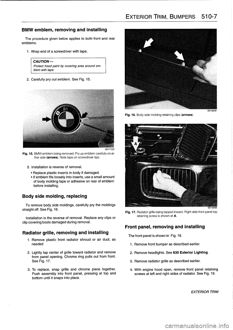
BMW
emblem,
removing
and
installing
The
procedure
given
below
applies
to
both
front
and
rear
emblems
.
1
.
Wrap
and
of
a
screwdriver
with
tape
.
CAUTION-
Protect
hood
paint
by
coveringarea
aroundem-
blem
with
tape
.
2
.
Carefully
pryout
emblem
.
See
Fig
.
15
.
UVI1'¿.
Fig
.
15
.
BMW
emblem
being
removed
.
Pry
up
emblem
carefully
on
ei-
ther
side
(arrows)
.
Note
tape
on
screwdriver
tips
.
3
.
Installation
is
reverse
of
removal
.
"
Replace
plastic
inserts
in
body
if
damaged
.
"
If
emblem
fits
loosely
intoinserts,
use
a
small
amount
of
bodymoldingtape
or
adhesiva
on
rear
of
emblem
before
installing
.
Body
side
molding,
replacing
To
remove
body
side
moldings,
carefully
pry
the
moldings
straight
off
.
See
Fig
.
16
.
Installation
is
the
reverse
of
removal
.
Replace
any
clips
or
clip
covering
boots
damaged
during
removal
.
Radiator
grille,
removing
and
installing
1
.
Remove
plastic
front
radiator
shroud
or
air
duct,
as
needed
2
.
Lightly
tap
center
of
grilla
toward
radiator
andremove
from
panel
opening
.
Chrome
ring
pulís
out
from
front
.
See
Fig
.
17
.
3
.
To
replace,
snap
grille
andchrome
piece
together
.
Push
assembly
into
front
panel,
pressing
at
top
and
bottom
until
it
snaps
into
place
.
EXTERIOR
TRIM,
BUMPERS
510-7
Fig
.
16
.
Body
sida
molding
retainingclips
(arrows)
.
-
0013048
Fig
.
17
.
Radiator
grille
being
tapped
inward
.
Right
side
front
panel
top
retaining
screw
is
shown
at
A
.
Front
panel,
removing
and
installing
The
front
panel
is
shown
in
Fig
.
18
.
1
.
Remove
front
bumper
as
described
earlier
.
2
.
Remove
headlights
.
See
630
Exterior
Lighting
.
3
.
Remove
radiator
grille
as
described
earlier
.
4
.
With
engine
hood
open,
remove
front
panel
retaining
screws
at
left
and
right
sides
of
radiator
.
See
Fig
.
19
.
EXTERIOR
TRIM