rear view mirror BMW 335I XDRIVE 2014 User Guide
[x] Cancel search | Manufacturer: BMW, Model Year: 2014, Model line: 335I XDRIVE, Model: BMW 335I XDRIVE 2014Pages: 242, PDF Size: 7.25 MB
Page 104 of 242
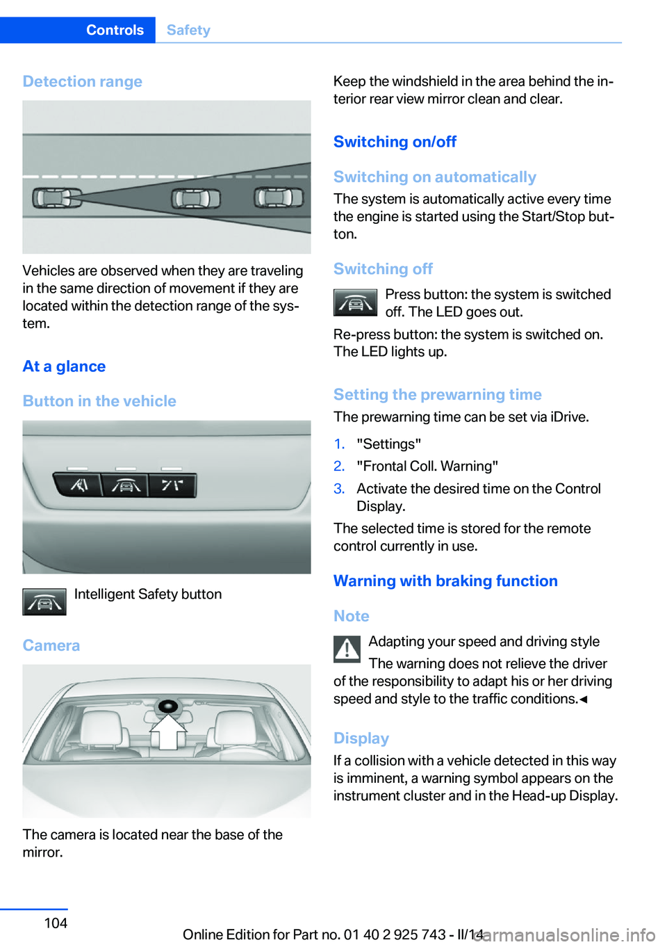
Detection range
Vehicles are observed when they are traveling
in the same direction of movement if they are
located within the detection range of the sys‐
tem.
At a glance
Button in the vehicle
Intelligent Safety button
Camera
The camera is located near the base of the
mirror.
Keep the windshield in the area behind the in‐
terior rear view mirror clean and clear.
Switching on/off
Switching on automatically The system is automatically active every time
the engine is started using the Start/Stop but‐
ton.
Switching off Press button: the system is switched
off. The LED goes out.
Re-press button: the system is switched on.
The LED lights up.
Setting the prewarning time The prewarning time can be set via iDrive.1."Settings"2."Frontal Coll. Warning"3.Activate the desired time on the Control
Display.
The selected time is stored for the remote
control currently in use.
Warning with braking function
Note Adapting your speed and driving styleThe warning does not relieve the driver
of the responsibility to adapt his or her driving
speed and style to the traffic conditions.◀
Display
If a collision with a vehicle detected in this way
is imminent, a warning symbol appears on the
instrument cluster and in the Head-up Display.
Seite 104ControlsSafety104
Online Edition for Part no. 01 40 2 925 743 - II/14
Page 109 of 242
Intelligent Safety button
Camera
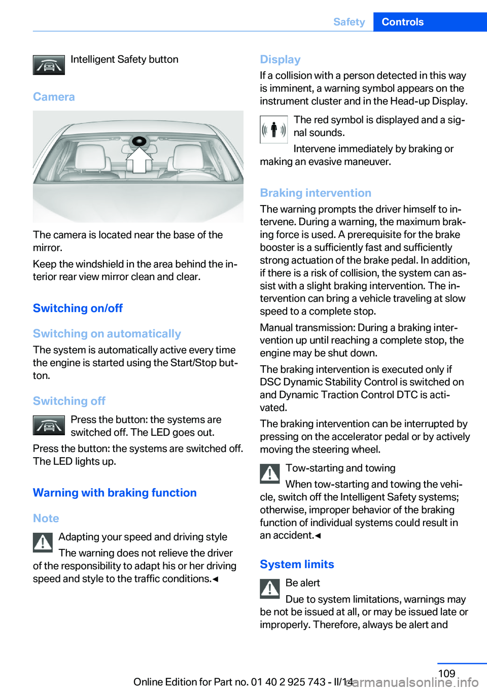
The camera is located near the base of the
mirror.
Keep the windshield in the area behind the in‐
terior rear view mirror clean and clear.
Switching on/off
Switching on automatically The system is automatically active every time
the engine is started using the Start/Stop but‐
ton.
Switching off Press the button: the systems are
switched off. The LED goes out.
Press the button: the systems are switched off.
The LED lights up.
Warning with braking function
Note Adapting your speed and driving style
The warning does not relieve the driver
of the responsibility to adapt his or her driving
speed and style to the traffic conditions.◀
Display
If a collision with a person detected in this way
is imminent, a warning symbol appears on the
instrument cluster and in the Head-up Display.
The red symbol is displayed and a sig‐
nal sounds.
Intervene immediately by braking or
making an evasive maneuver.
Braking intervention The warning prompts the driver himself to in‐
tervene. During a warning, the maximum brak‐
ing force is used. A prerequisite for the brake
booster is a sufficiently fast and sufficiently
strong actuation of the brake pedal. In addition,
if there is a risk of collision, the system can as‐
sist with a slight braking intervention. The in‐
tervention can bring a vehicle traveling at slow
speed to a complete stop.
Manual transmission: During a braking inter‐
vention up until reaching a complete stop, the
engine may be shut down.
The braking intervention is executed only if
DSC Dynamic Stability Control is switched on
and Dynamic Traction Control DTC is acti‐
vated.
The braking intervention can be interrupted by
pressing on the accelerator pedal or by actively
moving the steering wheel.
Tow-starting and towing
When tow-starting and towing the vehi‐
cle, switch off the Intelligent Safety systems;
otherwise, improper behavior of the braking
function of individual systems could result in
an accident.◀
System limits Be alert
Due to system limitations, warnings may
be not be issued at all, or may be issued late or
improperly. Therefore, always be alert andSeite 109SafetyControls109
Online Edition for Part no. 01 40 2 925 743 - II/14
Page 111 of 242
Camera
The camera is located near the base of the
mirror.
Keep the windshield in the area behind the in‐
terior rear view mirror clean and clear.
Switching on/off Press the button.
▷On: the LED lights up.▷Off: the LED goes out.
The setting is stored for the remote control
currently in use.
Display in the instrument cluster
▷Lines: system is activated.▷Arrows: at least one lane marking
was detected and warnings can be
issued.
Issued warning
If you leave the lane and if a lane marking has
been detected, the steering wheel begins vi‐
brating.
If the turn signal is set before changing the
lane, a warning is not issued.
End of warning
The warning ends:
▷Automatically after approx. 3 seconds.▷When returning to your own lane.▷When braking hard.▷When using the turn signal.
System limits
The system may not be fully functional in the
following situations:
▷In heavy fog, rain or snowfall.▷In the event of missing, worn, poorly visi‐
ble, merging, diverging, or multiple lane
markings such as in construction areas.▷When lane markings are covered in snow,
ice, dirt or water.▷In tight curves or on narrow lanes.▷When the lane markings are covered by
objects.▷When driving very close to the vehicle in
front of you.▷When driving toward bright lights.▷When the windshield in front of the interior
rearview mirror is fogged over, dirty or cov‐
ered with stickers, etc.▷During calibration of the camera immedi‐
ately after vehicle shipment.
Active Blind Spot Detection
The concept
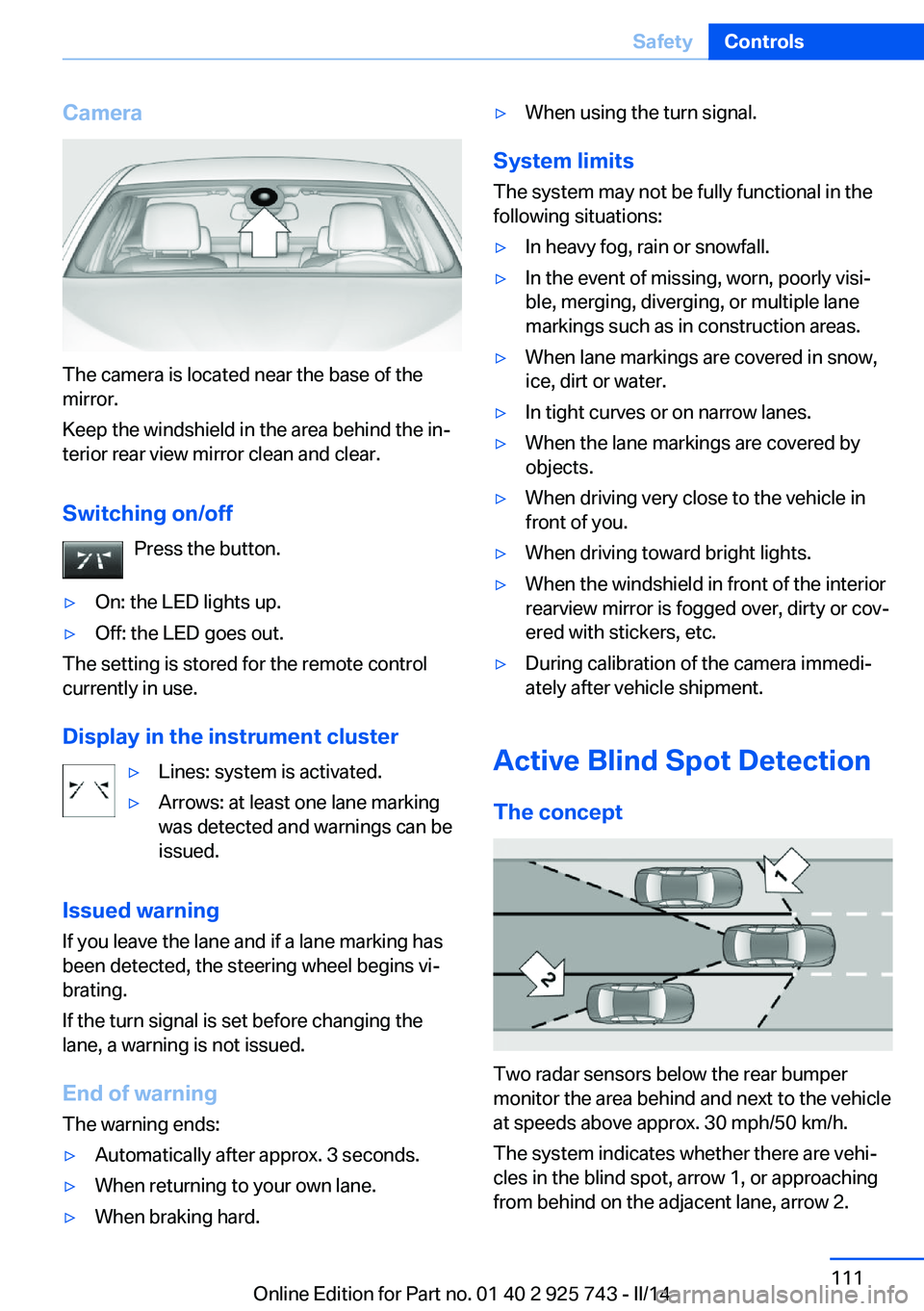
Two radar sensors below the rear bumper
monitor the area behind and next to the vehicle
at speeds above approx. 30 mph/50 km/h.
The system indicates whether there are vehi‐
cles in the blind spot, arrow 1, or approaching
from behind on the adjacent lane, arrow 2.
Seite 111SafetyControls111
Online Edition for Part no. 01 40 2 925 743 - II/14
Page 134 of 242
Switch the system back on if necessary.
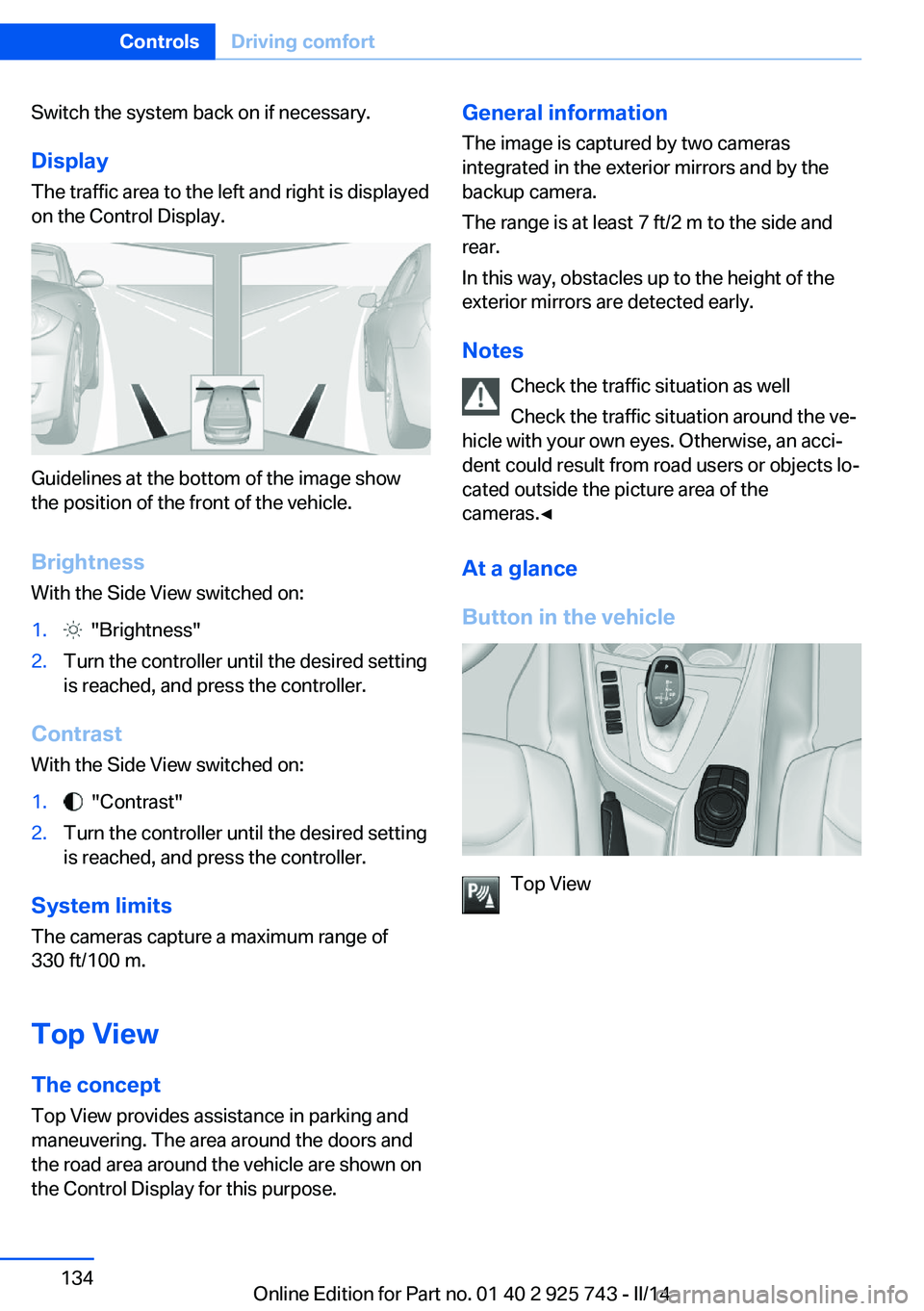
Display The traffic area to the left and right is displayed
on the Control Display.
Guidelines at the bottom of the image show
the position of the front of the vehicle.
Brightness With the Side View switched on:
1. "Brightness"2.Turn the controller until the desired setting
is reached, and press the controller.
Contrast
With the Side View switched on:
1. "Contrast"2.Turn the controller until the desired setting
is reached, and press the controller.
System limits
The cameras capture a maximum range of
330 ft/100 m.
Top View
The concept Top View provides assistance in parking and
maneuvering. The area around the doors and
the road area around the vehicle are shown on
the Control Display for this purpose.
General information
The image is captured by two cameras
integrated in the exterior mirrors and by the
backup camera.
The range is at least 7 ft/2 m to the side and
rear.
In this way, obstacles up to the height of the
exterior mirrors are detected early.
Notes Check the traffic situation as well
Check the traffic situation around the ve‐
hicle with your own eyes. Otherwise, an acci‐
dent could result from road users or objects lo‐
cated outside the picture area of the
cameras.◀
At a glance
Button in the vehicle
Top View
Seite 134ControlsDriving comfort134
Online Edition for Part no. 01 40 2 925 743 - II/14
Page 135 of 242
Cameras
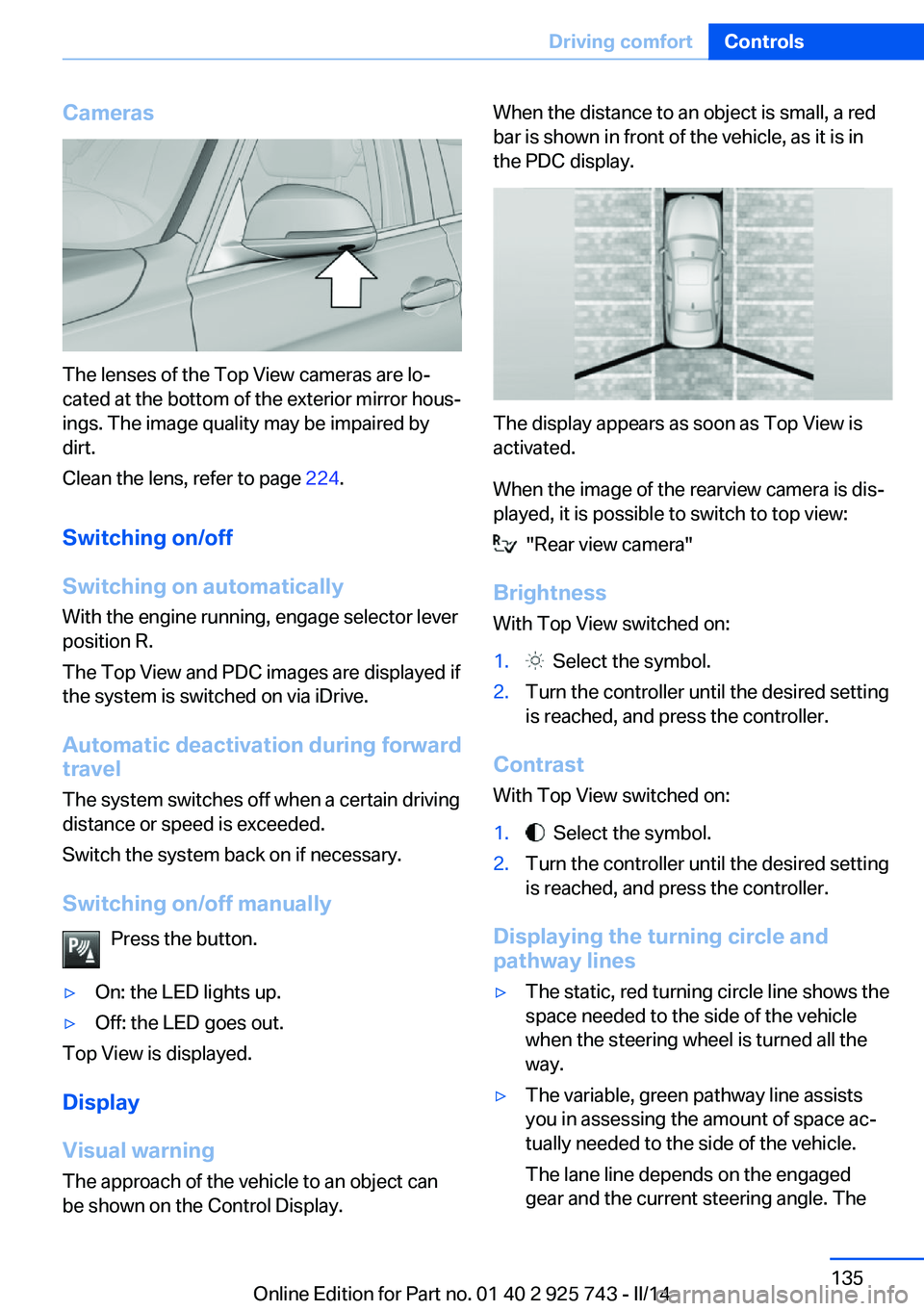
The lenses of the Top View cameras are lo‐
cated at the bottom of the exterior mirror hous‐
ings. The image quality may be impaired by
dirt.
Clean the lens, refer to page 224.
Switching on/off
Switching on automatically With the engine running, engage selector lever
position R.
The Top View and PDC images are displayed if
the system is switched on via iDrive.
Automatic deactivation during forward
travel
The system switches off when a certain driving
distance or speed is exceeded.
Switch the system back on if necessary.
Switching on/off manually Press the button.
▷On: the LED lights up.▷Off: the LED goes out.
Top View is displayed.
Display
Visual warning
The approach of the vehicle to an object can
be shown on the Control Display.
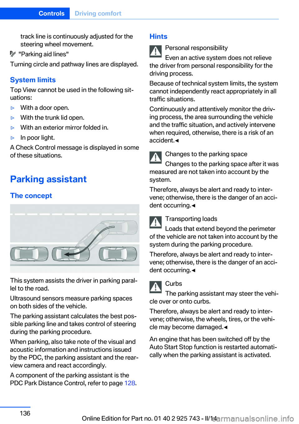
When the distance to an object is small, a red
bar is shown in front of the vehicle, as it is in
the PDC display.
The display appears as soon as Top View is
activated.
When the image of the rearview camera is dis‐
played, it is possible to switch to top view:
"Rear view camera"
Brightness With Top View switched on:
1. Select the symbol.2.Turn the controller until the desired setting
is reached, and press the controller.
Contrast
With Top View switched on:
1. Select the symbol.2.Turn the controller until the desired setting
is reached, and press the controller.
Displaying the turning circle and
pathway lines
▷The static, red turning circle line shows the
space needed to the side of the vehicle
when the steering wheel is turned all the
way.▷The variable, green pathway line assists
you in assessing the amount of space ac‐
tually needed to the side of the vehicle.
The lane line depends on the engaged
gear and the current steering angle. TheSeite 135Driving comfortControls135
Online Edition for Part no. 01 40 2 925 743 - II/14
Page 136 of 242
track line is continuously adjusted for the
steering wheel movement.
"Parking aid lines"
Turning circle and pathway lines are displayed.
System limits
Top View cannot be used in the following sit‐
uations:
▷With a door open.▷With the trunk lid open.▷With an exterior mirror folded in.▷In poor light.
A Check Control message is displayed in some
of these situations.
Parking assistant The concept
This system assists the driver in parking paral‐
lel to the road.
Ultrasound sensors measure parking spaces
on both sides of the vehicle.
The parking assistant calculates the best pos‐
sible parking line and takes control of steering
during the parking procedure.
When parking, also take note of the visual and
acoustic information and instructions issued
by the PDC, the parking assistant and the rear‐
view camera and react accordingly.
A component of the parking assistant is the
PDC Park Distance Control, refer to page 128.
Hints
Personal responsibility
Even an active system does not relieve
the driver from personal responsibility for the
driving process.
Because of technical system limits, the system
cannot independently react appropriately in all
traffic situations.
Continuously and attentively monitor the driv‐
ing process, the area surrounding the vehicle
and the traffic situation, and actively intervene
when required, otherwise, there is a risk of an
accident.◀
Changes to the parking space
Changes to the parking space after it was
measured are not taken into account by the system.
Therefore, always be alert and ready to inter‐
vene; otherwise, there is the danger of an acci‐
dent occurring.◀
Transporting loads
Loads that extend beyond the perimeter
of the vehicle are not taken into account by the
system during the parking procedure.
Therefore, always be alert and ready to inter‐
vene; otherwise, there is the danger of an acci‐
dent occurring.◀
Curbs
The parking assistant may steer the vehi‐
cle over or onto curbs.
Therefore, always be alert and ready to inter‐
vene; otherwise, the wheels, tires, or the vehi‐
cle may become damaged.◀
An engine that has been switched off by the
Auto Start Stop function is restarted automati‐
cally when the parking assistant is activated.Seite 136ControlsDriving comfort136
Online Edition for Part no. 01 40 2 925 743 - II/14
Page 148 of 242
Interior equipmentVehicle equipmentAll standard, country-specific and optional
equipment that is offered in the model series is
described in this chapter. Therefore, equip‐
ment is also described that is not available in a
vehicle, e. g., because of the selected optional
equipment or country variant. This also applies
for safety-related functions and systems.
Universal garage door
opener
The concept
The universal garage door opener can operate
up to 3 functions of remote-controlled sys‐
tems such as garage door drives or lighting
systems. The universal garage door opener re‐
places up to 3 different hand-held transmitters.
To operate the remote control, the buttons on
the interior rearview mirror must be program‐
med with the desired functions. The hand-held
transmitter for the particular system is required
in order to program the remote control.
During programming
During programming and before activat‐
ing a device using the integrated universal re‐
mote control, ensure that there are no people,
animals, or objects in the range of movement
of the remote-controlled device; otherwise,
there is a risk of injury or damage.
Also follow the safety instructions of the hand-
held transmitter.◀
Before selling the vehicle, delete the stored
functions for the sake of security.
Compatibility If this symbol is printed on the packag‐
ing or in the instructions of the system
to be controlled, the system is gener‐ally compatible with the universal garage door
opener.
If you have any questions, please contact:▷Your service center.▷www.homelink.com on the Internet.
HomeLink is a registered trademark of John‐
son Controls, Inc.
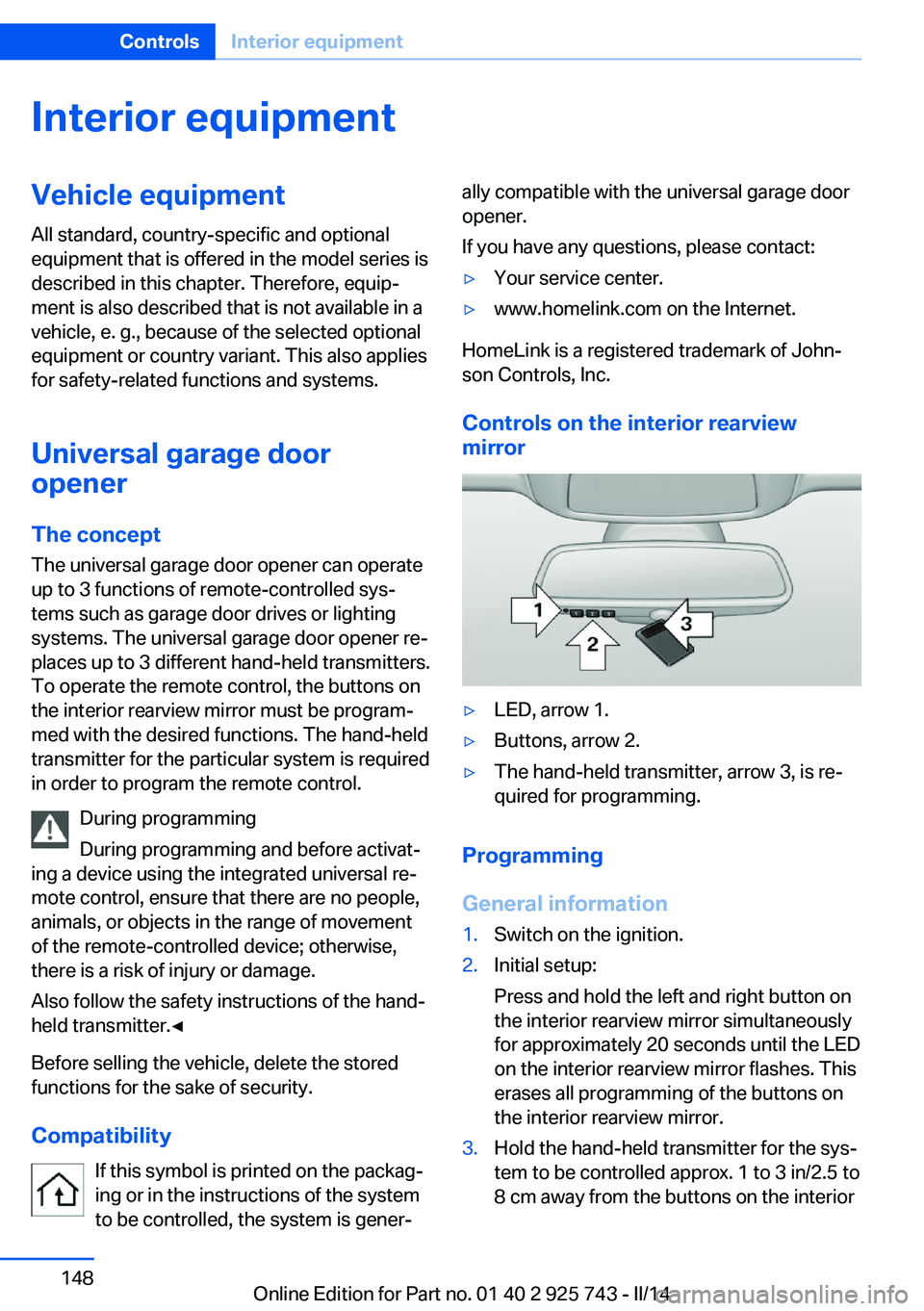
Controls on the interior rearview
mirror
▷LED, arrow 1.▷Buttons, arrow 2.▷The hand-held transmitter, arrow 3, is re‐
quired for programming.
Programming
General information
1.Switch on the ignition.2.Initial setup:
Press and hold the left and right button on
the interior rearview mirror simultaneously
for approximately 20 seconds until the LED
on the interior rearview mirror flashes. This
erases all programming of the buttons on
the interior rearview mirror.3.Hold the hand-held transmitter for the sys‐
tem to be controlled approx. 1 to 3 in/2.5 to
8 cm away from the buttons on the interiorSeite 148ControlsInterior equipment148
Online Edition for Part no. 01 40 2 925 743 - II/14
Page 149 of 242
rearview mirror. The required distance de‐
pends on the manual transmitter.4.Simultaneously press and hold the button
of the desired function on the hand-held
transmitter and the button to be program‐
med on the interior rearview mirror. The
LED on the interior rearview mirror will be‐
gin flashing slowly.5.Release both buttons as soon as the LED
flashes more rapidly. When the LED is
flashing faster, this indicates that the but‐
ton on the interior rearview mirror has been
programmed.
If the LED does not flash faster after at
least 60 seconds, change the distance be‐
tween the interior rearview mirror and the
hand-held transmitter and repeat the step.
Several more attempts at different distan‐
ces may be necessary. Wait at least
15 seconds between attempts.
Canada: if programming with the hand-
held transmitter was interrupted, hold
down the interior rearview mirror button
and repeatedly press and release the
hand-held transmitter button for 2 sec‐
onds.6.To program other functions on other but‐
tons, repeat steps 3 to 5.
The systems can be controlled using the inte‐
rior rearview mirror buttons.
Special feature of the alternating-
code wireless system
If you are unable to operate the system after
repeated programming, please check if the
system to be controlled features an alternat‐
ing-code system.
Read the system's operating manual, or press
the programmed button on the interior rear‐
view mirror longer. If the LED on the interior
rearview mirror starts flashing rapidly and then
stays lit constantly for 2 seconds, the system
features an alternating-code system. Flashing
and continuous illumination of the LED will re‐
peat for approximately 20 seconds.
For systems with an alternating-code system,
the universal garage door opener and the sys‐
tem also have to be synchronized.
Please read the operating manual of the sys‐
tem being set up for information on how to
synchronize the system.
Synchronizing is easier with the aid of a sec‐
ond person.
To synchronize:1.Park the vehicle within range of the re‐
mote-controlled system.2.Program the relevant button on the interior
rearview mirror as described.3.Locate and press the synchronizing button
on the system being programmed. You
have approx. 30 seconds for the next step.4.Hold down the programmed button on the
interior rearview mirror for approximately
3 seconds and then release it. If necessary,
repeat this work step up to three times in
order to finish synchronization. Once syn‐
chronization is complete, the programmed
function will be carried out.
Reprogramming individual buttons
1.Switch on the ignition.2.Press and hold the interior rearview mirror
button to be programmed.3.As soon as the interior rearview mirror LED
starts flashing slowly, hold the hand-held
transmitter for the system to be controlled
approx. 1 to 3 in/2.5 to 8 cm away from the
buttons on the interior rearview mirror. The
required distance depends on the manual
transmitter.4.Likewise, press and hold the button of the
desired function on the hand-held trans‐
mitter.5.Release both buttons as soon as the inte‐
rior rearview mirror LED flashes more rap‐
idly. When the LED is flashing faster, thisSeite 149Interior equipmentControls149
Online Edition for Part no. 01 40 2 925 743 - II/14
Page 150 of 242
indicates that the button on the interior
rearview mirror has been programmed.
The system can then be controlled by the
button on the interior rearview mirror.
If the LED does not flash faster after at
least 60 seconds, change the distance and
repeat the step. Several more attempts at
different distances may be necessary. Wait
at least 15 seconds between attempts.
Canada: if programming with the hand-
held transmitter was interrupted, hold
down the interior rearview mirror button
and repeatedly press and release the
hand-held transmitter button for 2 sec‐
onds.
Controls
Before operation
Before operating a system using the
integrated universal remote control, ensure
that there are no people, animals, or objects
within the range of movement of the remote- controlled system; otherwise, there is a risk of
injury or damage.
Also follow the safety instructions of the hand-
held transmitter.◀
The system, such as the garage door, can be
operated using the button on the interior rear‐
view mirror while the engine is running or when
the ignition is started. To do this, hold down
the button within receiving range of the system
until the function is activated. The interior rear‐ view mirror LED stays lit while the wireless sig‐
nal is being transmitted.
Deleting stored functions Press and hold the left and right button on the
interior rearview mirror simultaneously for ap‐
proximately 20 seconds until the LED flashes
rapidly. All stored functions are deleted. The
functions cannot be deleted individually.
Digital compass
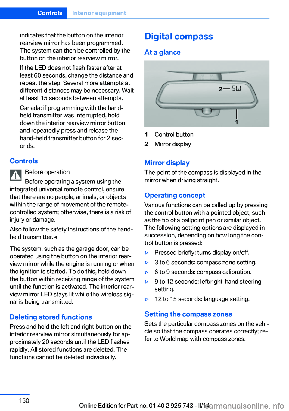
At a glance1Control button2Mirror display
Mirror display
The point of the compass is displayed in the
mirror when driving straight.
Operating concept
Various functions can be called up by pressing
the control button with a pointed object, such
as the tip of a ballpoint pen or similar object.
The following setting options are displayed in
succession, depending on how long the con‐
trol button is pressed:
▷Pressed briefly: turns display on/off.▷3 to 6 seconds: compass zone setting.▷6 to 9 seconds: compass calibration.▷9 to 12 seconds: left/right-hand steering
setting.▷12 to 15 seconds: language setting.
Setting the compass zones
Sets the particular compass zones on the vehi‐
cle so that the compass operates correctly; re‐
fer to World map with compass zones.
Seite 150ControlsInterior equipment150
Online Edition for Part no. 01 40 2 925 743 - II/14
Page 234 of 242
Control systems, driving sta‐bility 114
Convenient opening 35
Coolant 201
Coolant temperature 78
Cooling function 142, 145
Cooling, maximum 145
Cooling system 201
Corrosion on brake discs 164
Cruise control 125
Cruise control, active with Stop & Go 119
Cruising range 79
Cupholder 158
Current fuel consumption 80
D
Damage, tires 193
Damping control, dy‐ namic 115
Data, technical 228
Date 79
Daytime running lights 90
Defrosting, refer to defrosting the windows 142
Defrosting, refer to Windows, defrosting 146
Defrosting the windows 142
Dehumidifying, air 142, 145
Destination distance 84
Diesel exhaust fluid, at low temperatures 182
Diesel exhaust fluid, having refilled 182
Diesel exhaust fluid, on mini‐ mum 182
Diesel exhaust fluid, replen‐ ishing yourself 182
Diesel particulate filter 163
Digital clock 79
Digital compass 150
Dimensions 228
Dimmable exterior mirrors 55
Dimmable interior rearview mirror 56 Direction indicator, refer to
Turn signals 65
Display, electronic, instru‐ ment cluster 75
Display in windshield 87
Display lighting, refer to In‐ strument lighting 92
Displays 73
Displays, cleaning 224
Disposal, coolant 201
Disposal, vehicle battery 213
Distance control, refer to PDC 128
Distance to destination 84
Divided screen view, split screen 22
Door lock 37
Door lock, refer to Remote control 32
Drive-off assistant 118
Drive-off assistant, refer to DSC 114
Driver assistance, refer to In‐ telligent Safety 102
Driving Assistant, refer to In‐ telligent Safety 102
Driving Dynamics Con‐ trol 116
Driving instructions, breaking in 162
Driving mode 116
Driving notes, general 162
Driving stability control sys‐ tems 114
Driving style analysis 173
Driving tips 162
DSC Dynamic Stability Con‐ trol 114
DTC Dynamic Traction Con‐ trol 115
Dynamic Damping Con‐ trol 115
Dynamic Stability Control DSC 114
Dynamic Traction Control DTC 115 E
ECO PRO 169
ECO PRO, bonus range 170
ECO PRO display 169
ECO PRO driving mode 169
ECO PRO driving style analy‐ sis 173
ECO PRO mode 169
ECO PRO Tip - driving in‐ struction 171
EfficientDynamics 171
Electronic displays, instru‐ ment cluster 75
Electronic Stability Program ESP, refer to DSC 114
Emergency detection, remote control 33
Emergency release, fuel filler flap 178
Emergency Request 215
Emergency service, refer to Roadside Assistance 216
Emergency start function, en‐ gine start 33
Emergency unlocking, trunk lid 38
Energy Control 80
Energy recovery 80
Engine, automatic Start/Stop function 63
Engine, automatic switch- off 63
Engine compartment 196
Engine compartment, work‐ ing in 197
Engine coolant 201
Engine idling when driving, coasting 172
Engine oil 198
Engine oil, adding 199
Engine oil additives 199
Engine oil change 200
Engine oil filler neck 199
Engine oil temperature 78 Seite 234ReferenceEverything from A to Z234
Online Edition for Part no. 01 40 2 925 743 - II/14