seat BMW 5 SERIES GRAN TURISMO 2013 F07 Owner's Guide
[x] Cancel search | Manufacturer: BMW, Model Year: 2013, Model line: 5 SERIES GRAN TURISMO, Model: BMW 5 SERIES GRAN TURISMO 2013 F07Pages: 255, PDF Size: 7.25 MB
Page 69 of 255
Child restraint fixing system with a
tether strap
Mounting points
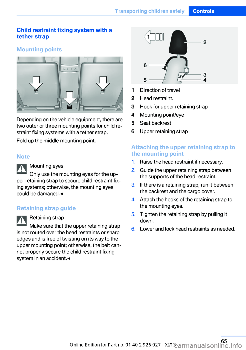
Depending on the vehicle equipment, there are
two outer or three mounting points for child re‐
straint fixing systems with a tether strap.
Fold up the middle mounting point.
Note Mounting eyes
Only use the mounting eyes for the up‐
per retaining strap to secure child restraint fix‐
ing systems; otherwise, the mounting eyes
could be damaged.◀
Retaining strap guide Retaining strap
Make sure that the upper retaining strap
is not routed over the head restraints or sharp
edges and is free of twisting on its way to the
upper mounting point; otherwise, the belt can‐
not properly secure the child restraint fixing
system in an accident.◀
1Direction of travel2Head restraint.3Hook for upper retaining strap4Mounting point/eye5Seat backrest6Upper retaining strap
Attaching the upper retaining strap to
the mounting point
1.Raise the head restraint if necessary.2.Guide the upper retaining strap between
the supports of the head restraint.3.If there is a retaining strap, run it between
the backrest and the cargo cover.4.Attach the hooks of the retaining strap to
the mounting eyes.5.Tighten the retaining strap by pulling it
down.6.Lower and lock head restraints as needed.Seite 65Transporting children safelyControls65
Online Edition for Part no. 01 40 2 909 928 - VI/13
Page 71 of 255
DrivingVehicle equipment
All standard, country-specific and optional
equipment that is offered in the model series is
described in this chapter. Therefore, equip‐
ment is also described that is not available in a
vehicle, e. g., because of the selected optional
equipment or country variant. This also applies
for safety-related functions and systems.
Start/Stop button The concept Pressing the Start/Stop button
switches the ignition on or off
and starts the engine.
The engine starts if the brake
pedal is pressed when you press
the Start/Stop button.
Ignition onPress the Start/Stop button and do not press
on the brake pedal at the same time.
All vehicle systems are ready for operation.
Most of the indicator and warning lamps in the
instrument cluster light up for varying lengths
of time.
To save battery power when the engine is off,
switch off the ignition and any unnecessary
electronic systems/power consumers.
The ignition switches off automatically:▷When locking the vehicle, even if the low
beams are switched on.▷Shortly before the battery is discharged
completely, so that the engine can still be
started.Note
If the engine is switched off and the ignition is
switched on, the system automatically
switches to the radio ready state when the
door is opened if the lights are switched off or
the daytime running lights are switched on.
Ignition off
Press the Start/Stop button again and do not
press on the brake pedal at the same time.
All indicator lamps in the instrument cluster go
out.
To save battery power when the engine is off,
switch off the ignition and any unnecessary
electronic systems/power consumers.
Transmission position P with the ignition
off
When the ignition is switched off, position P is
engaged automatically. When in an automatic
car wash, for example, ensure that the ignition
is not switched off accidentally.◀
The ignition automatically cuts off while the
vehicle is stationary and the engine is stopped:▷When locking the vehicle, and when the
low beams are activated.▷Shortly before the battery is discharged
completely, so that the engine can still be
started. This function is only available
when the low beams are switched off.▷When opening or closing the driver door, if
the driver's seat belt is unbuckled and the
low beams are switched off.▷While the driver's seat belt is unbuckled, if
the driver's door is open and the low
beams are switched off.
When the ignition is switched off, by opening
or closing the driver's door or unbuckling the
driver's seat belt, the radio ready state remains
active.
Seite 67DrivingControls67
Online Edition for Part no. 01 40 2 909 928 - VI/13
Page 73 of 255
Automatic Engine Start/Stop
Function
The concept The Auto Start/Stop function helps save fuel.
The system switches off the engine during a
stop, e.g., in a traffic congestion or at traffic
lights. The ignition remains switched on. The
engine starts again automatically for driving
off.
Certain vehicle components may experience
additional wear as a result of this system.
Automatic mode
The Auto Start/Stop function is operational af‐
ter each engine start.
This function is activated at speeds faster than
about 3 mph, approx. 5 km/h.
Engine stop
The engine is switched off automatically dur‐
ing a stop under the following conditions:
Automatic transmission:▷The selector lever is in transmission posi‐
tion D.▷The brake pedal remains pressed while the
vehicle is stationary or the vehicle is held
by Automatic Hold.▷The driver's seat belt is buckled or the driv‐
er's door is closed.
The air volume of the air conditioner is reduced
when the engine is switched off.
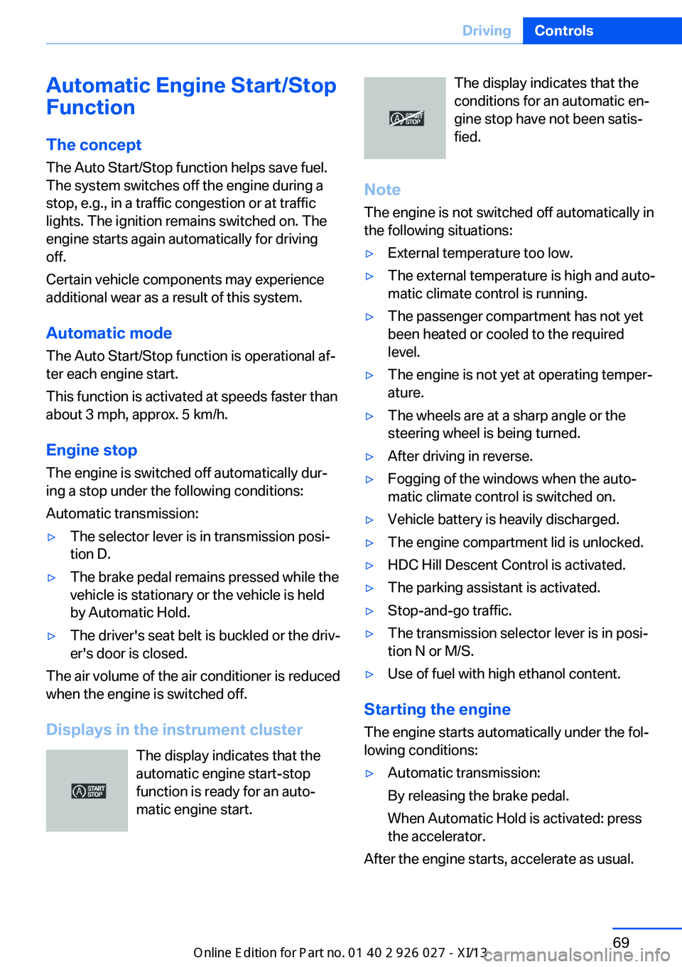
Displays in the instrument cluster The display indicates that the
automatic engine start-stop
function is ready for an auto‐
matic engine start.
The display indicates that the
conditions for an automatic en‐
gine stop have not been satis‐
fied.
Note
The engine is not switched off automatically in
the following situations:▷External temperature too low.▷The external temperature is high and auto‐
matic climate control is running.▷The passenger compartment has not yet
been heated or cooled to the required
level.▷The engine is not yet at operating temper‐
ature.▷The wheels are at a sharp angle or the
steering wheel is being turned.▷After driving in reverse.▷Fogging of the windows when the auto‐
matic climate control is switched on.▷Vehicle battery is heavily discharged.▷The engine compartment lid is unlocked.▷HDC Hill Descent Control is activated.▷The parking assistant is activated.▷Stop-and-go traffic.▷The transmission selector lever is in posi‐
tion N or M/S.▷Use of fuel with high ethanol content.
Starting the engine
The engine starts automatically under the fol‐
lowing conditions:
▷Automatic transmission:
By releasing the brake pedal.
When Automatic Hold is activated: press
the accelerator.
After the engine starts, accelerate as usual.
Seite 69DrivingControls69
Online Edition for Part no. 01 40 2 909 928 - VI/13
Page 107 of 255
Protective action
Airbags are not triggered in every impact situa‐
tion, e.g., in less severe accidents or rear-end
collisions.
Information on how to ensure the optimal
protective effect of the airbags▷Keep at a distance from the airbags.▷Always grasp the steering wheel on the
steering wheel rim, holding your hands at
the 3 o'clock and 9 o'clock positions, to
keep the danger of injury to your hands or
arms as low as possible if the airbag is trig‐
gered.▷There should be no people, animals, or ob‐
jects between an airbag and a person.▷Do not use the cover of the front airbag on
the front passenger side as a storage area.▷Keep the dashboard and window on the
front passenger side clear, i.e., do not
cover with adhesive labels or coverings,
and do not attach holders such as for navi‐
gation instruments and mobile phones.▷Make sure that the front passenger is sit‐
ting correctly, i.e., keeps his or her feet and
legs in the footwell; otherwise, leg injuries
can occur if the front airbag is triggered.▷Do not place slip covers, seat cushions or
other objects on the front passenger seat
that are not approved specifically for seats
with integrated side airbags.▷Do not hang pieces of clothing, such as
jackets, over the backrests.▷Make sure that occupants keep their heads
away from the side airbag and do not rest
against the head airbag; otherwise, injuries
can occur if the airbags are triggered.▷Do not remove the airbag restraint system.▷Do not remove the steering wheel.▷Do not apply adhesive materials to the air‐
bag cover panels, cover them or modify
them in any way.▷Never modify either the individual compo‐
nents or the wiring in the airbag system.
This also applies to steering wheel covers,
the dashboard, the seats, the roof pillars
and the sides of the headliner.◀
Even when all instructions are followed closely,
injury from contact with the airbags cannot be
ruled out in certain situations.
The ignition and inflation noise may lead to
short-term and, in most cases, temporary
hearing impairment in sensitive individuals.
In the case of a malfunction, deactivation
and after triggering of the airbags
Do not touch the individual components imme‐
diately after the system has been triggered;
otherwise, there is the danger of burns.
Only have the airbags checked, repaired or dis‐
mantled and the airbag generator scrapped by
your service center or a workshop that has the
necessary authorization for handling explo‐
sives.
Non-professional attempts to service the sys‐
tem could lead to failure in an emergency or
undesired triggering of the airbag, either of
which could result in injury.◀
Warnings and information on the airbags are
also found on the sun visors.
Functional readiness of the airbag
system
When the ignition is switch on, the
warning lamp in the instrument cluster
lights up briefly and thereby indicates
the operational readiness of the entire airbag
system and the belt tensioner.
Airbag system malfunctioning
▷Warning lamp does not come on when the
ignition is turned on.▷The warning lamp lights up continuously.Seite 103SafetyControls103
Online Edition for Part no. 01 40 2 909 928 - VI/13
Page 108 of 255
When there is a malfunction, have the
airbag system checked immediately
When there is a malfunction, have the airbag
system checked immediately; otherwise, there
is a risk that the system does not function as
expected in the event of an accident despite
corresponding severity of the accident.◀
Automatic deactivation of the front passenger airbags
The system determines whether the front pas‐
senger seat is occupied by measuring the re‐
sistance of the human body.
The front, knee, and side airbag on the front passenger side are activated or deactivated
accordingly.
Leave feet in the footwell
Make sure that the front passenger
keeps his or her feet in the footwell; otherwise,
the front passenger airbags may not function properly.◀
Child restraint fixing system in the front
passenger seat
Before transporting a child on the front pas‐
senger seat, refer to the safety notes and in‐
structions under Children on the front passen‐
ger seat.◀
Malfunction of the automaticdeactivation system
When transporting older children and adults,
the front passenger airbags may be deacti‐
vated in certain sitting positions. In this case,
the indicator lamp for the front passenger air‐
bags lights up.
In this case, change the sitting position so that
the front passenger airbags are activated and
the indicator lamp goes out.
If it is not possible to activate the airbags, have
the person sit in the rear.
To make sure that the occupied seat cushion
can be evaluated correctly▷Do not attach covers, cushions, ball mats
or other items to the front passenger seat
unless they are specifically recommended
by the manufacturer of your vehicle.▷Do not place any electronic devices on the
passenger seat if a child restraint system is
to be installed on it.▷Do not place objects under the seat that
could press against the seat from below.
Indicator lamp for the front passenger
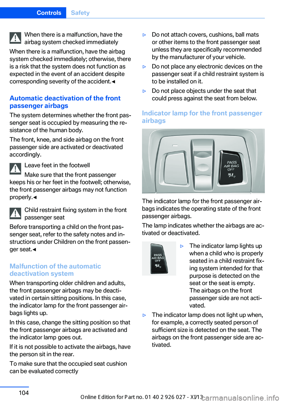
airbags
The indicator lamp for the front passenger air‐
bags indicates the operating state of the front
passenger airbags.
The lamp indicates whether the airbags are ac‐
tivated or deactivated.
▷The indicator lamp lights up
when a child who is properly
seated in a child restraint fix‐
ing system intended for that
purpose is detected on the
seat or the seat is empty.
The airbags on the front
passenger side are not acti‐
vated.▷The indicator lamp does not light up when,
for example, a correctly seated person of
sufficient size is detected on the seat. The
airbags on the front passenger side are ac‐
tivated.Seite 104ControlsSafety104
Online Edition for Part no. 01 40 2 909 928 - VI/13
Page 109 of 255
Detected child seatsThe system generally detects children seated
in a child seat, especially in the child seats that
were required by NHTSA when the vehicle was
manufactured. After installing a child seat,
make sure that the indicator lamp for the front
passenger airbags lights up. This indicates that the child seat has been detected and the
front passenger airbags are not activated.
Strength of the driver's and front
passenger airbag
The strength with which the driver's and front
passenger airbags are triggered depends on
the position of the driver's and front passenger
seats.
To maintain the accuracy of this function over
the long-term, calibrate the front seats when a
corresponding message appears on the Con‐
trol Display.
Calibrating the front seats A corresponding message appears on the
Control Display.1.Move the respective seat forward all the
way.2.Move the respective seat forward again. It
moves forward briefly.3.Readjust the seat to the desired position.
The calibration procedure is completed when
the message on the Control Display disap‐
pears.
If the message continues to be displayed, re‐
peat the calibration.
If the message does not disappear after a re‐
peat calibration, have the system checked as
soon as possible.
Unobstructed area of movement
Ensure that the area of movement of the
seats is unobstructed to avoid personal injury
or damage to objects.◀
FTM Flat Tire Monitor
The concept
The system does not measure the actual infla‐
tion pressure in the tires.
It detects a pressure loss in a tire by comparing
the rotational speeds of the individual wheels
while moving.
In the event of a pressure loss, the diameter
and therefore the rotational speed of the corre‐
sponding wheel change. This is detected and
reported as a flat tire.
Functional requirements
The system must have been initialized when
the tire inflation pressure was correct; other‐
wise, reliable signaling of a flat tire is not en‐
sured. Initialize the system after each correc‐
tion of the tire inflation pressure and after
every tire or wheel change.
Status display The current status of the Flat Tire Monitor can
be displayed on the Control Display, e.g.,
whether or not the FTM is active.1."Vehicle Info"2."Vehicle status"3. "Flat Tire Monitor (FTM)"
The status is displayed.
Initialization
The initialization process adopts the set infla‐
tion tire pressures as reference values for the
detection of a flat tire. Initialization is started by
confirming the inflation pressures.
Do not initialize the system when driving with
snow chains.
1."Vehicle Info"2."Vehicle status"3. "Perform reset"4.Start the engine - do not drive away.Seite 105SafetyControls105
Online Edition for Part no. 01 40 2 909 928 - VI/13
Page 130 of 255
NotePersonal responsibility
The system cannot possibly serve as a
substitute for the driver's personal judgment of
the traffic situation. The system may not al‐
ways detect critical situations reliably and in a
timely manner. Adapt speed to traffic situation
and drive alertly; otherwise, a risk to safety may
result.◀
Function
After the safety belt is buckled, the front belts
are automatically pretensioned once after the
vehicle is driven is away.
In critical driving situations, the following indi‐
vidual functions become active as needed:▷The front belts are automatically preten‐
sioned.▷Automatic closing of the windows.▷Automatic closing of the glass sunroof.▷For vehicles equipped with Comfort Seats:
automatic positioning of the backrest for
the front passenger seat.
After a critical driving situation without an acci‐
dent, the front belts are loosened again. All
other systems can be restored to the desired
setting.
If the belt tension does not loosen automati‐
cally, stop the vehicle and unbuckle the belt
using the red button in the buckle. Fasten the
belt before continuing on your trip.
PostCrash
In the event of an accident, the system can
bring the car to a halt automatically without in‐
tervention by the driver in certain situations.
This can reduce the risk of a further collision
and the consequences thereof.
Depressing the brake pedal can cause the ve‐
hicle to brake harder. This interrupts automatic
braking. Depressing the accelerator pedal also
interrupts automatic braking.
After coming to a halt, the brake is released
automatically. Secure the vehicle against roll‐
ing.Seite 126ControlsSafety126
Online Edition for Part no. 01 40 2 909 928 - VI/13
Page 155 of 255
Obstacle marking
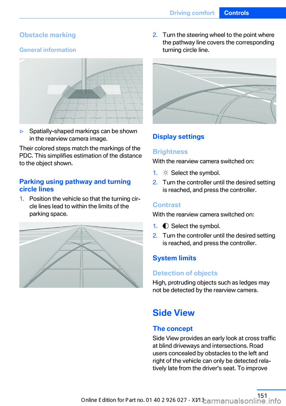
General information▷Spatially-shaped markings can be shown
in the rearview camera image.
Their colored steps match the markings of the
PDC. This simplifies estimation of the distance
to the object shown.
Parking using pathway and turning
circle lines
1.Position the vehicle so that the turning cir‐
cle lines lead to within the limits of the
parking space.2.Turn the steering wheel to the point where
the pathway line covers the corresponding
turning circle line.
Display settings
Brightness
With the rearview camera switched on:
1. Select the symbol.2.Turn the controller until the desired setting
is reached, and press the controller.
Contrast
With the rearview camera switched on:
1. Select the symbol.2.Turn the controller until the desired setting
is reached, and press the controller.
System limits
Detection of objects
High, protruding objects such as ledges may
not be detected by the rearview camera.
Side View The concept Side View provides an early look at cross traffic
at blind driveways and intersections. Road
users concealed by obstacles to the left and
right of the vehicle can only be detected rela‐
tively late from the driver's seat. To improve
Seite 151Driving comfortControls151
Online Edition for Part no. 01 40 2 909 928 - VI/13
Page 166 of 255
Climate controlVehicle equipment
All standard, country-specific and optional
equipment that is offered in the model series is
described in this chapter. Therefore, equip‐ment is also described that is not available in a
vehicle, e. g., because of the selected optional
equipment or country variant. This also applies
for safety-related functions and systems.
Automatic climate control
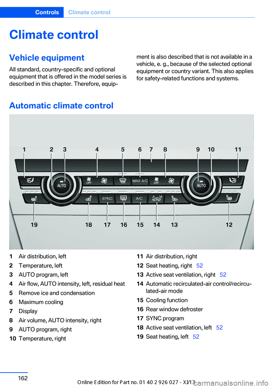
1Air distribution, left2Temperature, left3AUTO program, left4Air flow, AUTO intensity, left, residual heat5Remove ice and condensation6Maximum cooling7Display8Air volume, AUTO intensity, right9AUTO program, right10Temperature, right11Air distribution, right12Seat heating, right 5213Active seat ventilation, right 5214Automatic recirculated-air control/recircu‐
lated-air mode15Cooling function16Rear window defroster17SYNC program18Active seat ventilation, left 5219Seat heating, left 52Seite 162ControlsClimate control162
Online Edition for Part no. 01 40 2 909 928 - VI/13
Page 169 of 255
Switching on1.Switch off the ignition.2. Press the right side of the button
on the driver's side.
The symbol appears on the automatic cli‐
mate Control Display.
The interior temperature, air volume and air
distribution can be adjusted with the ignition
switched on.
Switching off
At the lowest fan speed, press the left side of
the button on the driver's side.
The symbol on the display of the automatic
climate control flashes.
Switching the system on/off Switching off
▷Complete system: Press and hold the left button on
the driver's side until the control
clicks off.▷On the front passenger side:
Press and hold the left button on
the front passenger side.
Switching on
Press any button except:
▷SYNC program.▷Rear window defroster.▷Left side of Air volume button.▷Seat heating.▷Seat ventilation.
Microfilter/activated-charcoal filter
The microfilter removes dust and pollen from
the incoming air.
The activated-charcoal filter removes gaseous
pollutants from the outside air that enters the
vehicle.
This combined filter should be replaced during
scheduled maintenance, refer to page 216, of
your vehicle.
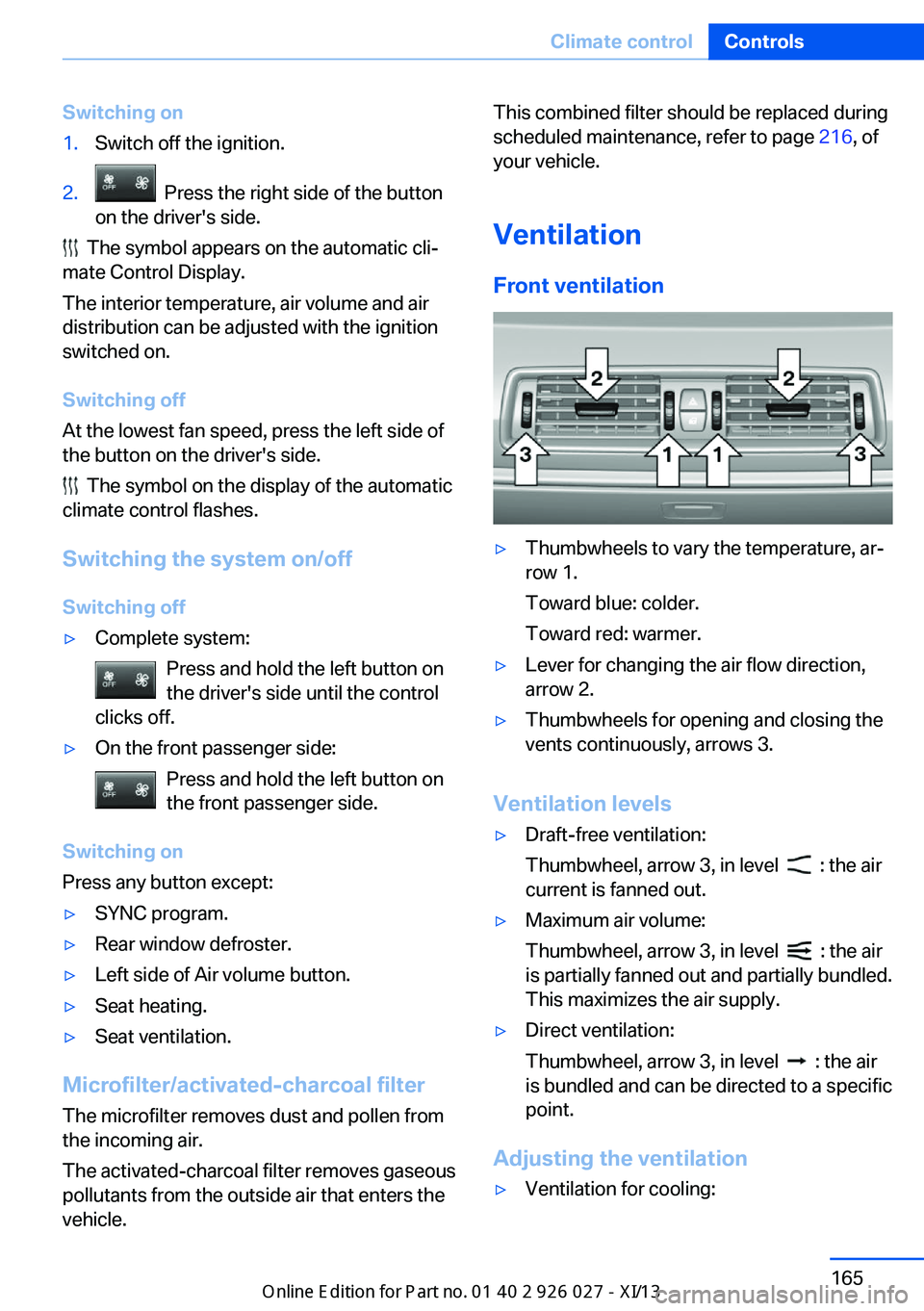
Ventilation Front ventilation▷Thumbwheels to vary the temperature, ar‐
row 1.
Toward blue: colder.
Toward red: warmer.▷Lever for changing the air flow direction,
arrow 2.▷Thumbwheels for opening and closing the
vents continuously, arrows 3.
Ventilation levels
▷Draft-free ventilation:
Thumbwheel, arrow 3, in level
: the air
current is fanned out.
▷Maximum air volume:
Thumbwheel, arrow 3, in level
: the air
is partially fanned out and partially bundled.
This maximizes the air supply.
▷Direct ventilation:
Thumbwheel, arrow 3, in level
: the air
is bundled and can be directed to a specific
point.
Adjusting the ventilation
▷Ventilation for cooling:Seite 165Climate controlControls165
Online Edition for Part no. 01 40 2 909 928 - VI/13