rear BMW 525i 1997 E39 Workshop Manual
[x] Cancel search | Manufacturer: BMW, Model Year: 1997, Model line: 525i, Model: BMW 525i 1997 E39Pages: 1002
Page 749 of 1002
Downloaded from www.Manualslib.com manuals search engine
Final Drive
Final drive, removing and installing
- Raise rear of car.
WARNING-
Make sure that the car is firmly supported on jack stands de-
signed for the purpose. Place the jaclc stands beneath struc-
tural chassis
~oints. Do not i lace iaclc stands under
( suspension barfs.
Remove exhaust system. See 180 Exhaust System.
Disconnect drive shaft from final drive. See
260 Driveshaft.
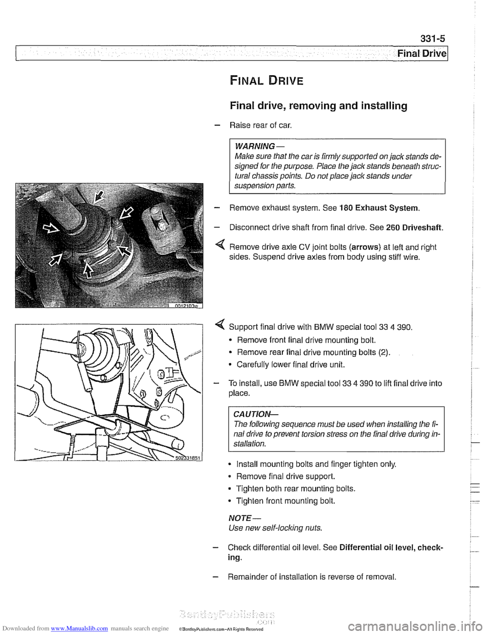
Remove drive axle CV joint bolts (arrows) at left and right
sides. Suspend drive axles from body using stiff wire.
4 Support final drive with BMW special tool 33 4 390.
* Remove front final drive mounting bolt.
Remove rear final drive mounting bolts
(2).
Carefully lower final drive unit.
- To install, use BMW special tool 33 4 390 to lift final drive into
place.
CA UTIOP&
The following sequence must be used when installing the fi-
nal drive to prevent torsion stress on the final drive during in-
Install mounting bolts and finger tighten only.
Remove final drive support.
Tighten both rear mounting bolts.
Tighten front mounting bolt.
NOTE-
Use new self-locking nuts.
- Check differential oil level. See Differential oil level, check-
ing.
- Remainder of installation is reverse of removal.
Page 750 of 1002
Downloaded from www.Manualslib.com manuals search engine
Final Drive
Tightening torques
F~nal drive to rear axle carrier 105 Nm (77 it-lb)
Driveshaft CV joint to final drive flange
- MlO (Torx bolt) 70
Nm (51 ft-lb)
- M8 (compression nut) 32 Nm (24
ft-lb)
Drive axle to final drive
ilange
Torx bolts (M10) 83 Nm (61 ft-lb)
Torx bolt with
rlbbed teeth (M10) 64 Nm (47 ft-lb)
Torx bolt
wlth ribbed teeth (MI0 sliver) 80 Nm (59 ft-lb)
Torx
bolt with ribbed teeth (M10 black) 100 Nm (74 ft-lb)
* Torx bolt with ribbed teeth (M12) 135 Nm (100 ft-lb)
Differential oil level, checking
The E39 differential is filled with lifetime oil that ordinarily
does not need to be changed. BMW recommends using only
a specially formulated synthetic gear oil
(SAF-XO) that is
available through an authorized BMW dealer parts depart-
ment. For additional information on this lubricant and any oth-
er lubricants that may be compatible, contact an authorized
BMW dealer service department.
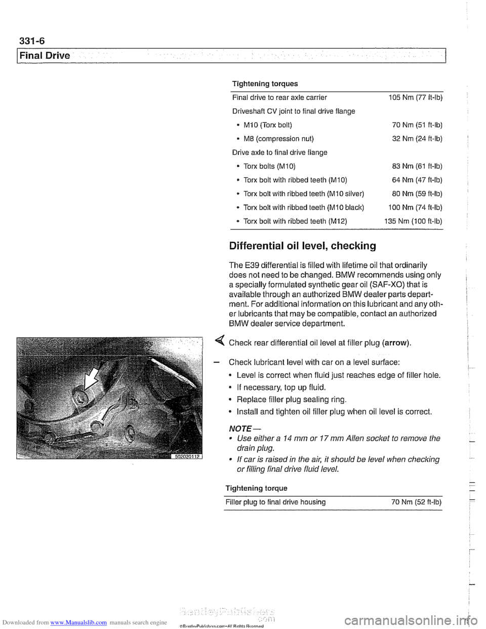
< Check rear differential oil level at filler plug (arrow).
- Check lubricant level with car on a level surface:
Level is correct when fluid just reaches edge of filler hole.
If necessary, top up fluid.
* Replace filler plug sealing ring.
Install and tighten oil filler plug when oil level is correct.
NOTE-
Use either a 14 mm or 17 mm Allen socket to remove the
drain plug.
If car is raised in the air. it should be level when
checkino " or filling final drive fluid level.
- Tightening torque -
Filler plug to final drive housing 70 Nm (52
ft-lb) -
Page 756 of 1002
Downloaded from www.Manualslib.com manuals search engine
331-12
Final Drive Final drive cover, removing and installing
- Remove final drive. See Final drive, removing and install-
ing.
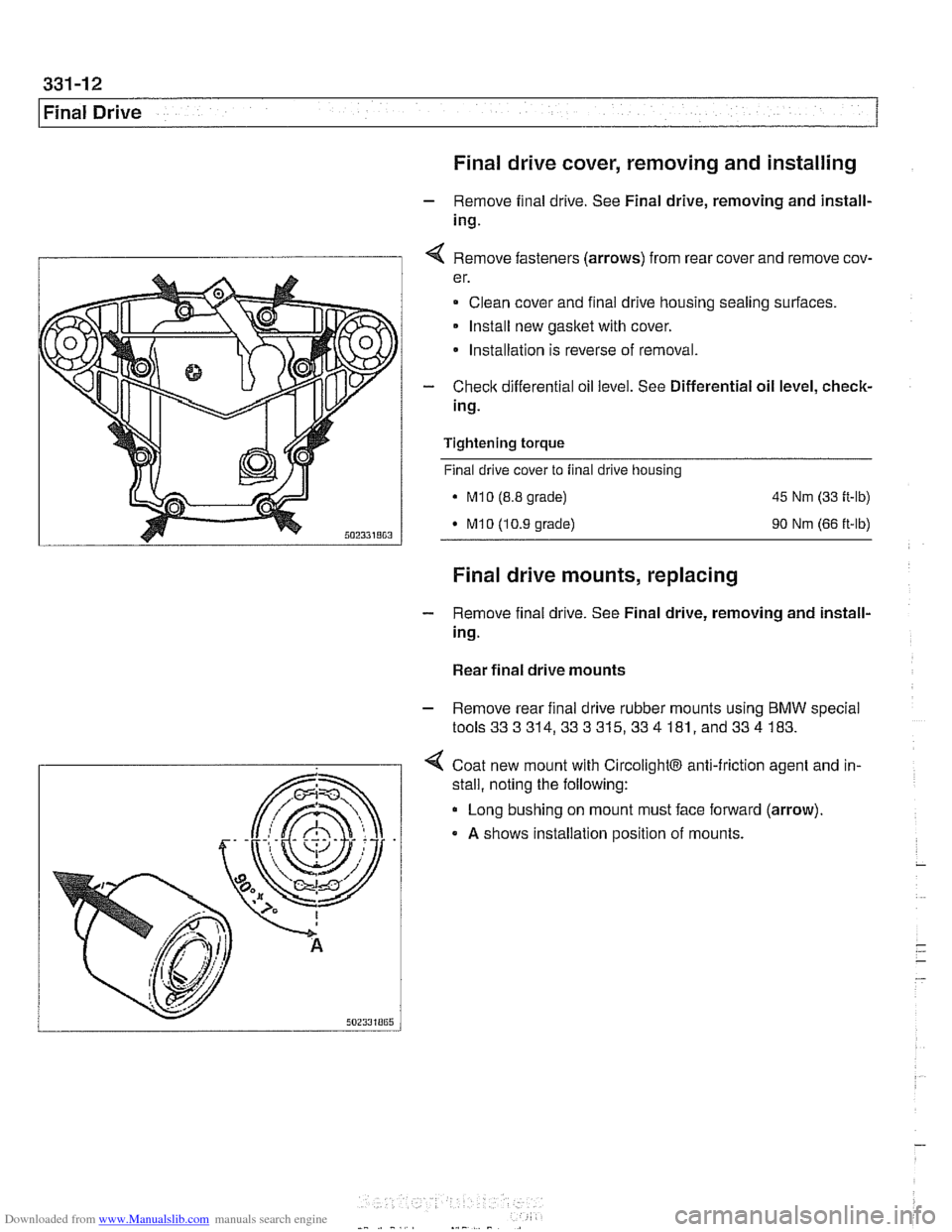
I 1 4 Remove fasteners (arrows) from rear cover and remove cov-
er.
Clean cover and final drive housing sealing surfaces.
Install new
gasket with cover.
* Installation is reverse of removal.
- Check differential oil level. See Differential oil level, check-
ing.
Tightening
torque
Final drive cover to final drive housing
. M10 (8.8 grade) 45 Nm (33 ft-lb)
M10 (10.9 grade) 90 Nm (66 ft-lb)
Final drive mounts, replacing
- Remove final drive. See Final drive, removing and install-
ing.
Rear final drive mounts
- Remove rear final drive rubber mounts using BMW special
tools333314,333315,334 181, and334 183.
4 Coat new mount with CircolightB anti-friction agent and in-
.
stall, noting the following:
Long bushing on mount must face forward (arrow).
A shows installation position of mounts.
Page 757 of 1002
Downloaded from www.Manualslib.com manuals search engine
Final Drive
Front final drive mount
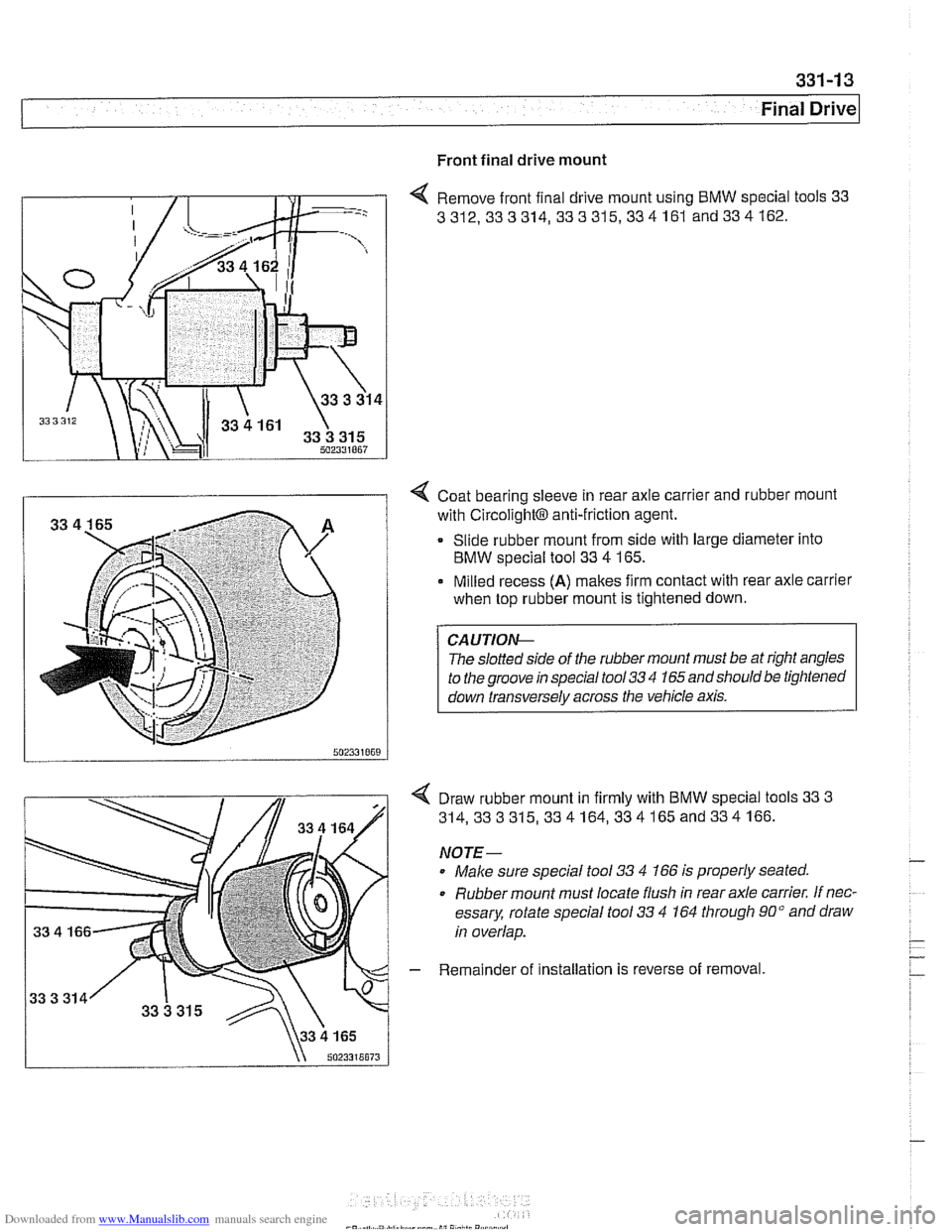
4 Remove front final drive mount using BMW special tools 33
3312,333314, 333315,334161
and334162.
I i 4 Coat bearing sleeve in rear axle carrier and rubber mount
with
~ircolight~ anti-friction agent.
Slide rubber mount from side with large diameter into
BMW special tool 33
4 165.
Milled recess
(A) makes firm contact with rear axle carrier
when top rubber mount is tightened down.
The
slolled srde ot r11e rubber mounl must be ar r#ghl angles
lo
rhe groove rn specal roo/ 33 '1 165 and shoulo be lrghrened
I down ~ransversely across the vehicle axis. I
Draw rubber mount in firmly with BMW special tools 33 3
314,333315,334164,334165and334166.
NOTE-
Male sure special tool 33 4 166 is properly seated.
0 Rubber mount must locate flush in rear axle carrier. If nec-
essary, rotate special tool
33 4 164 through 90" and draw
in overlap.
- Remainder of installation is reverse of removal
Page 758 of 1002
Downloaded from www.Manualslib.com manuals search engine
Final Drive
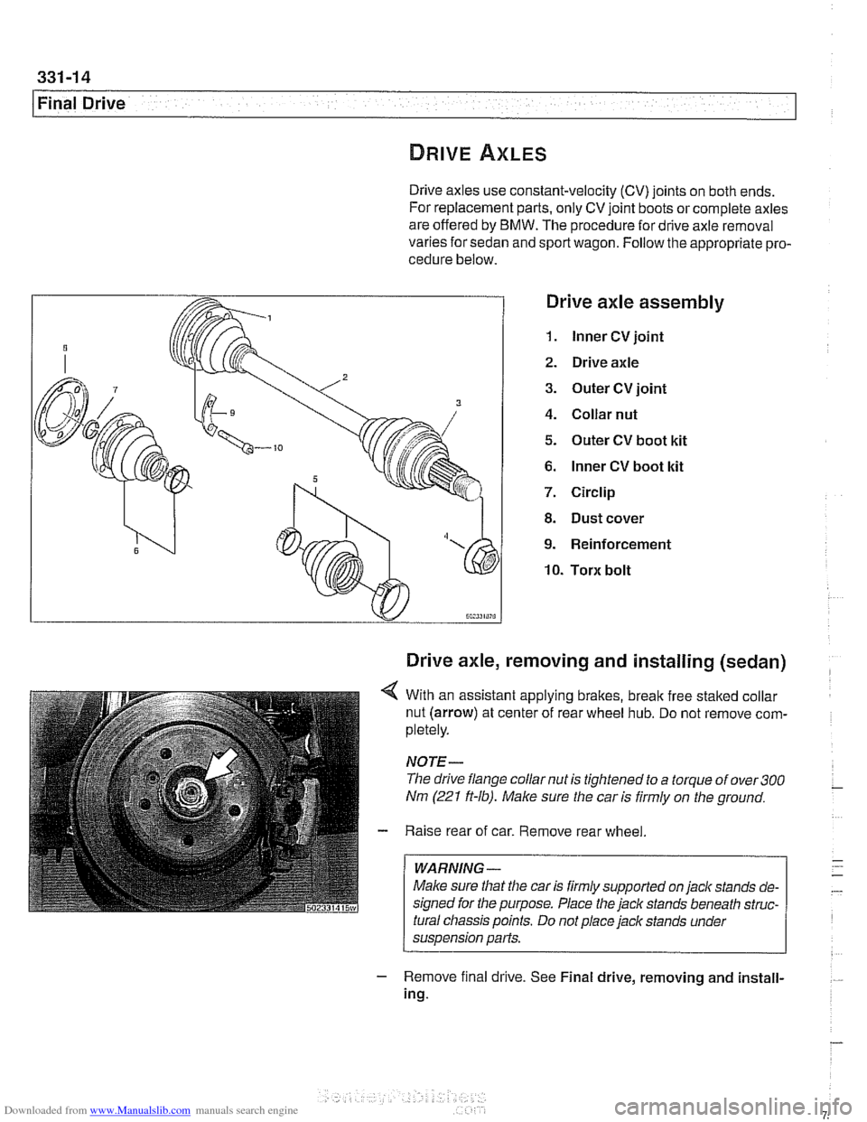
Drive axles use constant-velocity (CV) joints on both ends.
For replacement parts, only CV joint boots or complete axles
are offered by BMW. The procedure for drive axle removal
varies for sedan and sport wagon. Follow the appropriate pro-
cedure below.
Drive axle assembly
1. lnner CV joint
2. Drive axle
3. Outer CV joint
4. Collar nut
5. Outer CV boot kit
6. lnner CV boot kit
7. Circlip
8. Dust cover
9. Reinforcement
10. Torx bolt
Drive axle, removing and installing (sedan)
4 With an assistant applying brakes, break free staked collar
nut (arrow) at center of rear wheel hub. Do not remove com-
pletely.
NOTE-
The drive flange collar nut is tightened to a torque of over 300
Nm (221 ft-lb). Male sure the car is firmly on the ground.
- Raise rear of car. Remove rear wheel
WARNING -
Make sure that the car is firmly supported on jack stands de-
signed for the purpose. Place the
jack stands beneath struc-
tural chassis points. Do not place jack stands under
suspension parts.
- Remove f~nal drrve. See Final drive, removing and install-
ing.
Page 759 of 1002
Downloaded from www.Manualslib.com manuals search engine
Final ~rivel
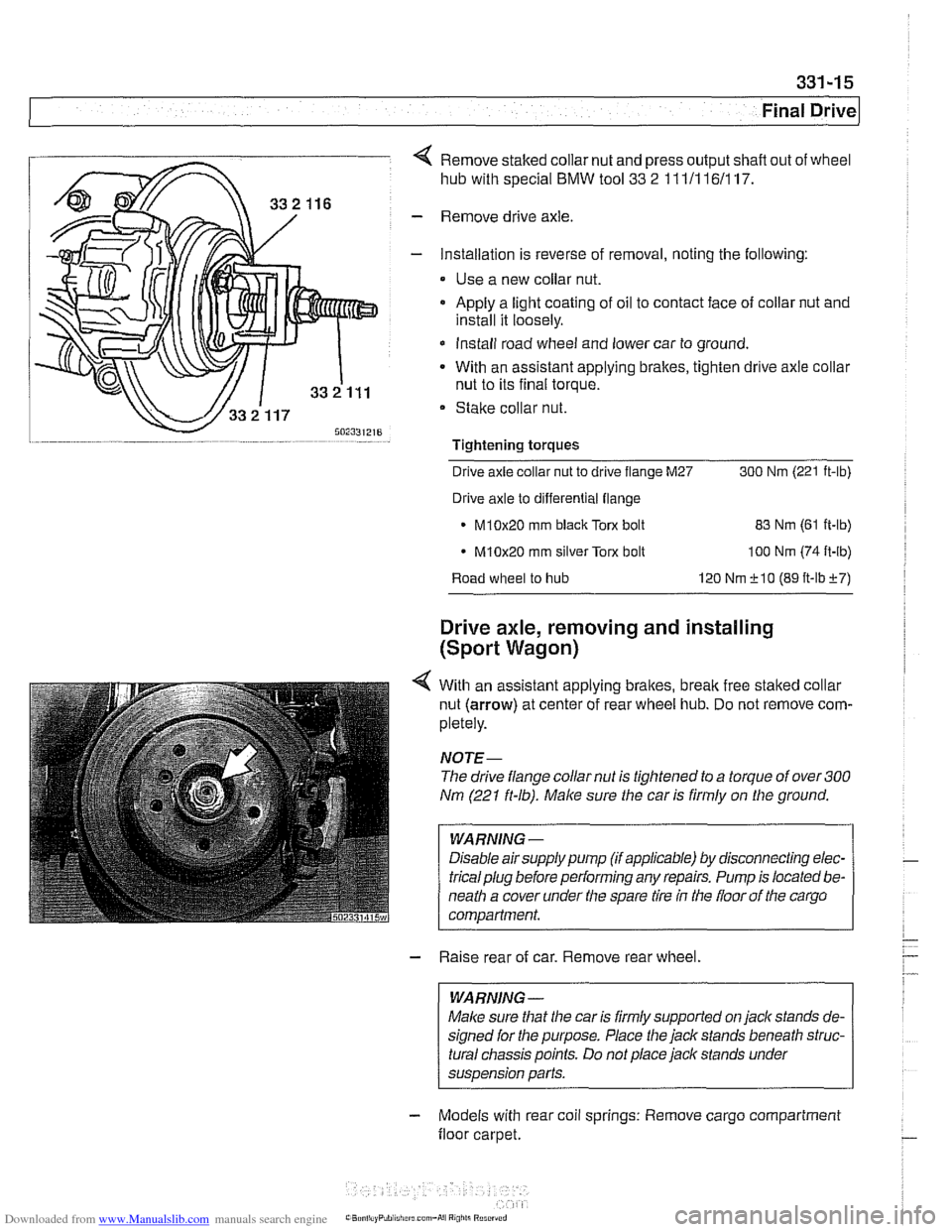
4 Remove staked collar nut and press output shafl out of wheel
hub with special
BMW tool 33 2 111/116/117.
- Remove drive axle.
- Installation is reverse of removal, noting the following:
Use a new collar nut.
a Apply a light coating of oil to contact face of collar nut and
install it loosely.
* Install road wheel and lower car to ground.
- With an assistant applying brakes, tighten drive axle collar
nut to its final torque.
Stake collar nut.
Tightening torques
-
Drive axle collar nut to drive flange M27 300 Nrn (221 ft-lb)
Drive axle to differential flange
* M10x20 rnm black Torx bolt
83 Nrn (61 ft-lb)
M10x20 rnrn silver Torx bolt
100 Nrn (74 ft-lb)
Road wheel to hub 120 Nrn f 10 (89 ft-lbf7)
Drive axle, removing and installing
(Sport Wagon)
4 With an assistant applying brakes, brealc free staked collar
nut (arrow) at center of rear wheel hub. Do not remove com-
pletely.
NOJE-
The drive flange collar nut is tightened to a torque of over 300
Nm (221 ft-lb). Make sure the car is firmly on the ground.
WARNING -
Disable airsupply pump (if applicable) by disconnecting elec-
tricalplug before performing any repairs. Pump is located be-
neath a cover under the spare tire
in the floor of the cargo
compartment.
- Raise rear of car. Remove rear wheel.
WARNING -
Malce sure that the car is firmly supported on jack stands de-
signed for the purpose. Place the jack stands beneath struc-
tural chassis points. Do not place jack stands under
suspension parts.
- Models with rear coil springs: Remove cargo compartment
floor carpet.
Page 766 of 1002
Downloaded from www.Manualslib.com manuals search engine
E39 brake system
BMW E39 models are equipped with vacuum power-assisted
four-wheel disc brakes with an integral
Antilock Brake System
(ABS). Single-piston calipers act on vented front and rear ro-
tors. A brake pad wear sensor for each axle indicates when
brake pads need replacement. The dual drum-type parking
brake system is integrated with the rear brake rotors.
Electronic braking and stability control
E39 models were introduced with Automatic Stability Control,
a computer controlled traction control system that uses the
AB5 system in conjunction with engine management controls
to control wheel spin during take-off and maintain vehicle sta-
bility while braking.
Added in the
1998 model year was Dynamic Stability Control
(DSC). This system implements wheel speed modulation
throughout all stages of driving. For example, DSC is able to
reduce understeer by applying differing amounts of braking
force to each wheel, or it can override the engine manage-
ment system during hard cornering.
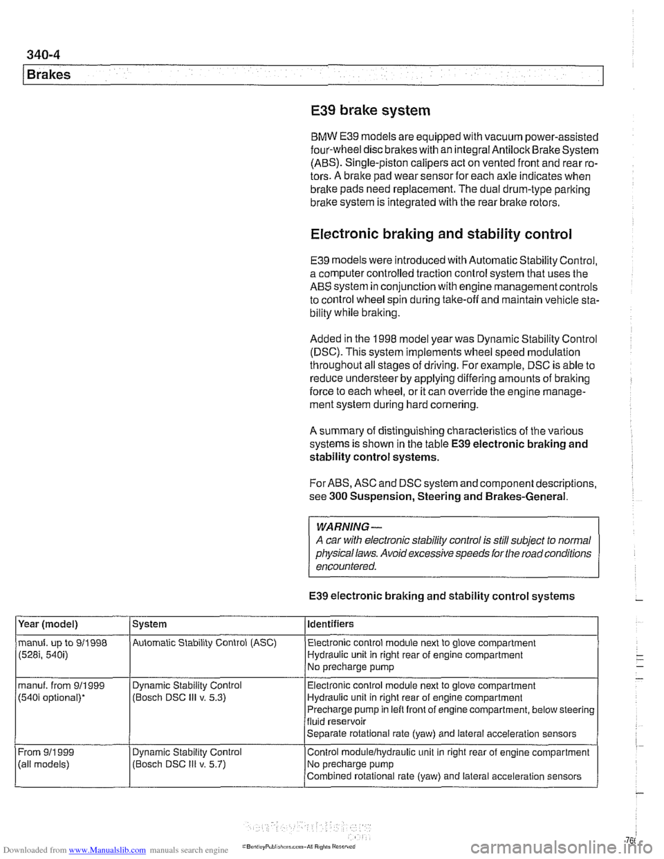
A summary of distinguishing characteristics of the various
systems is shown in the table
E39 electronic braking and
stability control systems.
For ABS, ASC and DSC system and component descriptions,
see
300 Suspension, Steering and Brakes-General.
WARNING-
A car with electronic stability control is still subject to normal
physical laws. Avoid excessive speeds for the road conditions
encountered.
E39 electronic braking and stability control systems
Year (model)
manuf. up to 911998
(528i, 540i)
manuf. from 911999
(540i optional)*
From
911 999
(ail models) System
Automatic Stability Control (ASC) Identifiers
Electronic control module next to glove compartment
Hydraulic unit in right rear of engine compartment
No precharge pump
Dynamic Stability Control
(Bosch DSC
Ill v. 5.3)
Dynamic
Stabil~ty Control
(Bosch DSC
Ill v. 5.7) Electronic
control module next to glove compartment
Hydraulic unit in right rear of engine compartment
Precharge pump in left front of engine compartment, below steering
fluid reservoir
Separate rotational rate (yaw) and lateral acceleration sensors
Control
modulelhydraulic unit in right rear of engine compartment
No precharge pump
Combined rotational rate (yaw) and lateral acceleration sensors
Page 768 of 1002
Downloaded from www.Manualslib.com manuals search engine
340-6
1 Brakes
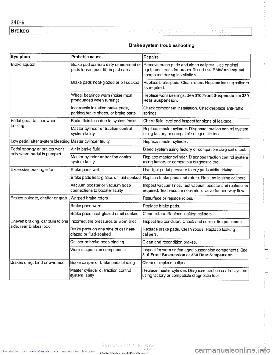
Brake system troubleshooting
/symptom I Probable cause 1 Repairs
Brake squeal
Pedal goes to floor when
bralting
Low pedal after system bleeding
Pedal spongy or brakes work
only when pedal is pumped
Excessive braking effort
Brakes pulsate, chatter or grab
Uneven
bralting, car pulls to one
side, rear braltes
loclt
Brakes drag, bind or overheat Brake
pad carriers dirty or corroded or
pads loose (poor fit) in pad carrier
Braite pads heat-glazed or oil-soaked
Wheel bearings worn (noise most
pronounced when turning)
Incorrectly Installed brake pads,
parking bralte shoes, or bralte parts
Brake fluid loss due to system leaks
Master cylinder or traction control
system faulty
Master cylinder faulty
Air in braite fluid
Master cylinder or traction control
system faulty
Brake pads wet
Brake pads
heat-glazedorfluid-soalted
Vacuum booster or vacuum hose
connections to booster faulty
--- Warped brake rotors
Brake pads worn
Brake pads heat-glazed or oil-soaked Remove
brake pads and clean calipers. Use original
equipment pads for proper fit and use BMW anti-squeal
compound during installation,
Replace brake pads. Ciean rotors. Replace leaking caliper:
as required.
Replace worn bearings. See 310 Front Suspension
or33C
Rear Suspension.
Check component installation. Checldreplace anti-rattle
springs.
Checlt fluid level and inspect for signs of leakage.
Replace master cylinder. Diagnose traction control system
using factory or compatible diagnostic tool.
Replace master cylinder.
Bleed system using factory or compatible diagnostic tool.
Replace master cylinder. Diagnose traction control system
using factory or compatible diagnostic tool.
Use light pedal pressure to dry pads while driving.
Replace
bralte pads and rotors. Replace leaking calipers.
lnspect vacuum lines. Test vacuum booster and replace as
required. Test vacuum non-return valve for one-way flow.
Resurface or replace rotors.
Replace brake pads.
Clean rotors. Replace leaiting calipers.
Incorrect tire pressures or worn tires
Brake pads on one side of car heat-
glazed or fluid-soaked
Caliper or brake pads binding
Worn suspension components
Brake caliper or brake pads binding
Master cylinder or traction control
system faulty lnspect
tire condition. Checlt and correct tire pressures.
Replace brake pads. Clean rotors. Replace leaking
calipers.
Clean and recondition brakes.
Inspect for worn or damaged suspension components. See
310 Front Suspension or 330 Rear Suspension.
Ciean or replace caliper.
Replace master cylinder. Diagnose traction control system
using faclory or compatible diagnostic tool.
Page 770 of 1002
Downloaded from www.Manualslib.com manuals search engine
340-8
1 Brakes
Brake bleeding is usually done for one of two reasons: either
to replace old brake fluid as part of routine maintenance or to
expel trapped air in the system that resulted
from opening the
brake hydraulic system during repairs.
Read the
Warnings listed below before beginning the bleed-
ing procedure an on any
E39 car. If air enters the ACS or DSC
hydraulic unit, the factory BMW Service Tester MUST be
used in conjunction with a bralte pressure bleeder before the
vehicle is driven.
The BMW
ServiceTester (DISpluslGT1iMoDiC) must be
used to bleed the braltes if:
Any hydraulic brake system components are replaced, in-
cluding bralte lines.
Air has enter the
ABSIASC or ABSlDSC hydraulic unit.
WARNING -
* The ASC and DSC systems use electronic controls and a
sophisticated hydraulic unit Once air enters the hydraulic
unit, it is very difficult to remove using traditional methods.
For this reason, pressure
brake bleeding should be done
in conjunction with the BMW
Sewice Tester (DIS-
plus/GTl/MoDiC). The tester electrically cycles the hy-
draulic unit solenoids in the hydraulic unit while
pressurized brake fluid is forced through the system.
When flushing the brake fluid from the system, use ex-
treme care to not let the
brale fluid reservoir run dry If
air enters the hydraulic unit, the BMW Service Tester
MUST be used to bleed the brale system before the
vehicle is driven.
Always use new brake fluid from an unopened container. It is
important to bleed the entire system when any part of the hy-
draulic system has been opened. Be sure to have the special
equipment needed before beginning the job.
When bleeding the
braltes, start atthe wheel farthest from the
master cylinder and progress in the following order:
right rear brake
left rear brake
* right front brake
left front brake
Page 771 of 1002
Downloaded from www.Manualslib.com manuals search engine
Brakes
Brakes, bleeding
The procedure below requires a BMW Service Tester (DIS-
pluslGTl/MoDiC).
- Determine type of traction control (ASC, DSC with precharge
pump, DSC without precharge pump). Be sure to use correct
specification brake fluid, according to application table below.
Brake fluid applications
ABS I ASC and ABS / DSC models DOT 4 brake fluid
with precharge pump (to 911998)
ABS I DSC models without precharge DOT 4 low viscosity
pump (911998 and later) brake
fluid
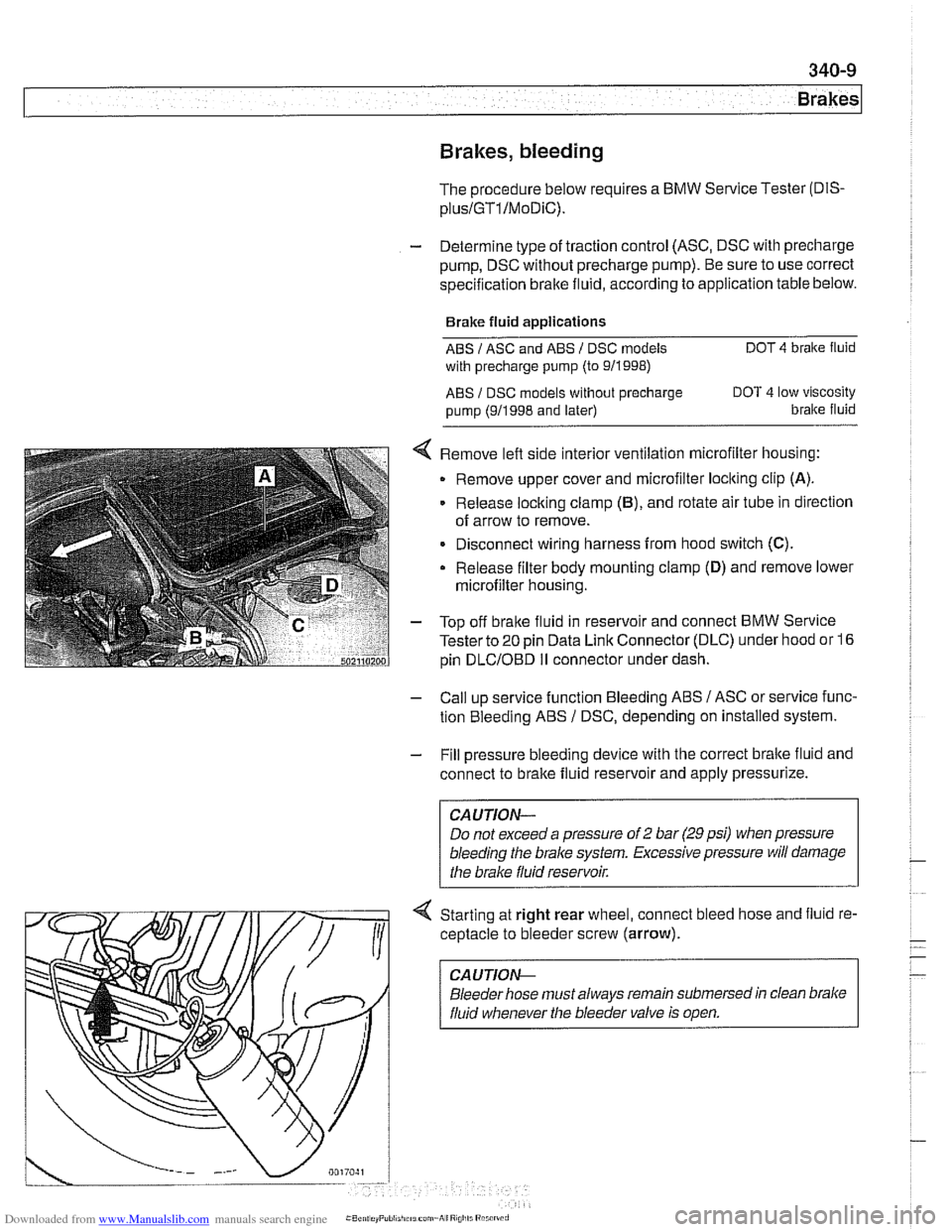
< Remove left side interior ventilation microfilter housing:
Remove upper cover and microfilter loclting clip
(A).
Release locking clamp (B), and rotate air tube in direction
of arrow to remove.
Disconnect wiring harness from hood switch
(C).
Release filter body mounting clamp (D) and remove lower
microfilter housing.
- Top off bralte fluid in reservoir and connect BMW Service
Tester to
20 pin Data Link Connector (DLC) under hood or 16
pin
DLCIOBD I1 connector under dash.
- Call up service function Bleeding ABS / ASC or service func-
tion Bleeding ABS
/ DSC, depending on installed system.
- Fill pressure bleeding device with the correct brake fluid and
connect to brake fluid reservoir and apply pressurize.
Do not exceed a pressure of
2 bar (29 psi) when pressure
bleeding the
brake system. Excessive pressure will damage
4 Starting at right rear wheel, connect bleed hose and fluid re-
ceptacle to bleeder screw (arrow).
CA UTlON-
Bleeder hose must always remain submersed in clean brake
fluid whenever the bleeder valve is open.