rear BMW 525i 1997 E39 Workshop Manual
[x] Cancel search | Manufacturer: BMW, Model Year: 1997, Model line: 525i, Model: BMW 525i 1997 E39Pages: 1002
Page 803 of 1002
Downloaded from www.Manualslib.com manuals search engine
400-9
Body-General
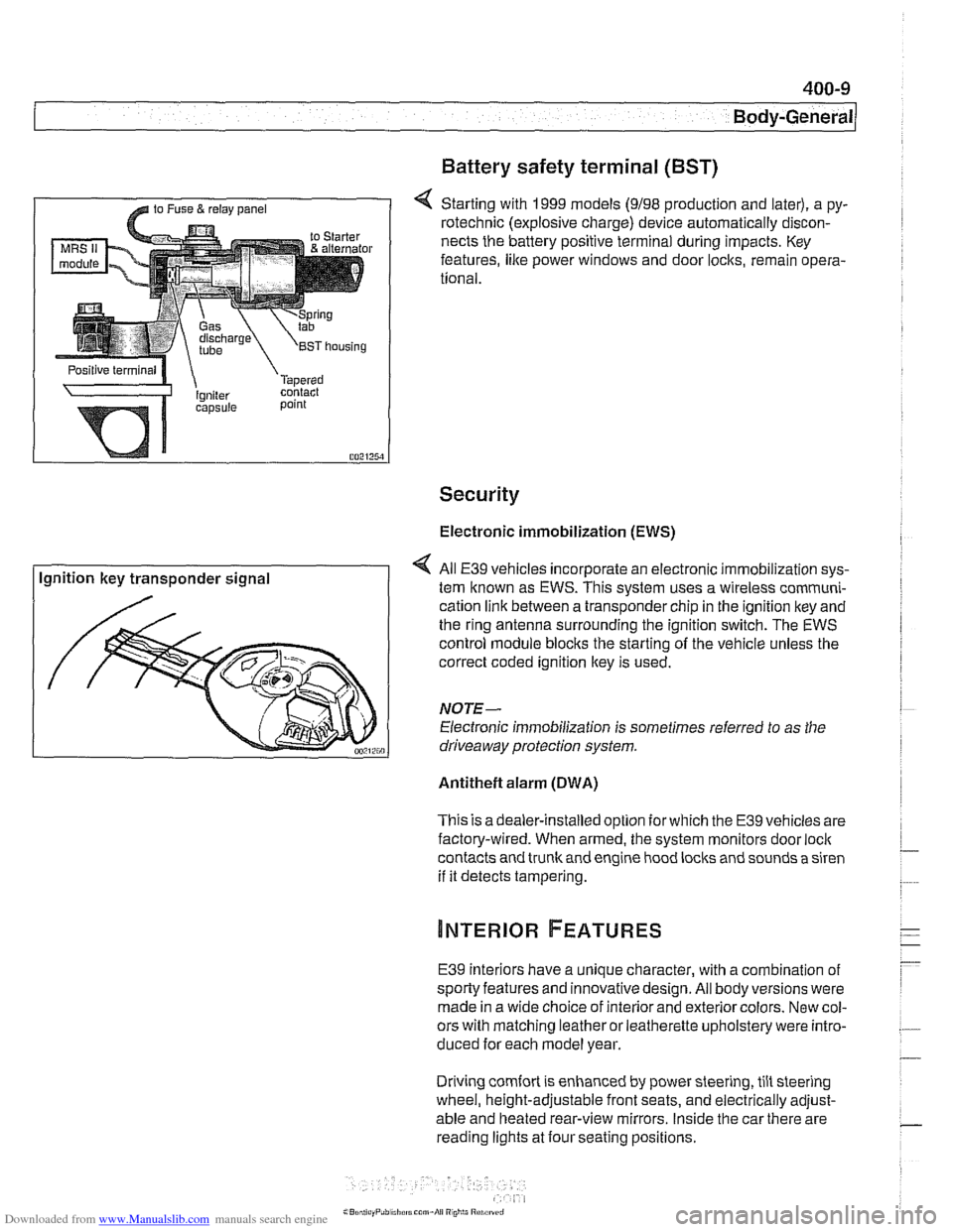
Battery safety terminal
(BST)
4 Starting with 1999 models (9198 production and later), a py-
rotechnic (explosive charge) device automatically discon-
nects the battery positive terminal during impacts. Key
features,
like power windows and door locks, remain opera-
tional.
Security
Electronic immobilization (EWS)
Ignition key transponder signal All
E39 vehicles incorporate an electronic immobilization sys-
tem known as EWS. This svstem uses a wireless comrnuni-
cation link between a transponder chip in the ignition key and
the ring antenna surrounding the ignition switch. The EWS
control module blocks the starting of the vehicle unless the
correct coded ignition key is used.
NOTE-
Electronic immobilization is sometimes referred to as the
driveaway protection system.
Antitheft alarm (DWA)
This is adealer-installed option for which the E39 vehicles are
factory-wired. When armed, the system monitors door
loci(
contacts and trunk and engine hood locks and sounds a siren
if it detects tampering.
E39 interiors have a unique character, with a combination
of
sporty features and innovativedesign. All body versions were
made in a wide choice of interior and exterior colors. New col-
ors with matching leather or leatherette upholstery were intro-
duced for each model year.
Driving
comfort is enhanced by power steering, tilt steering
wheel, height-adjustable front seats, and electrically adjust-
able and heated rear-view mirrors. Inside the car there are
reading lights at four seating positions.
Page 804 of 1002
Downloaded from www.Manualslib.com manuals search engine
400-1 0
Body-General
Seats
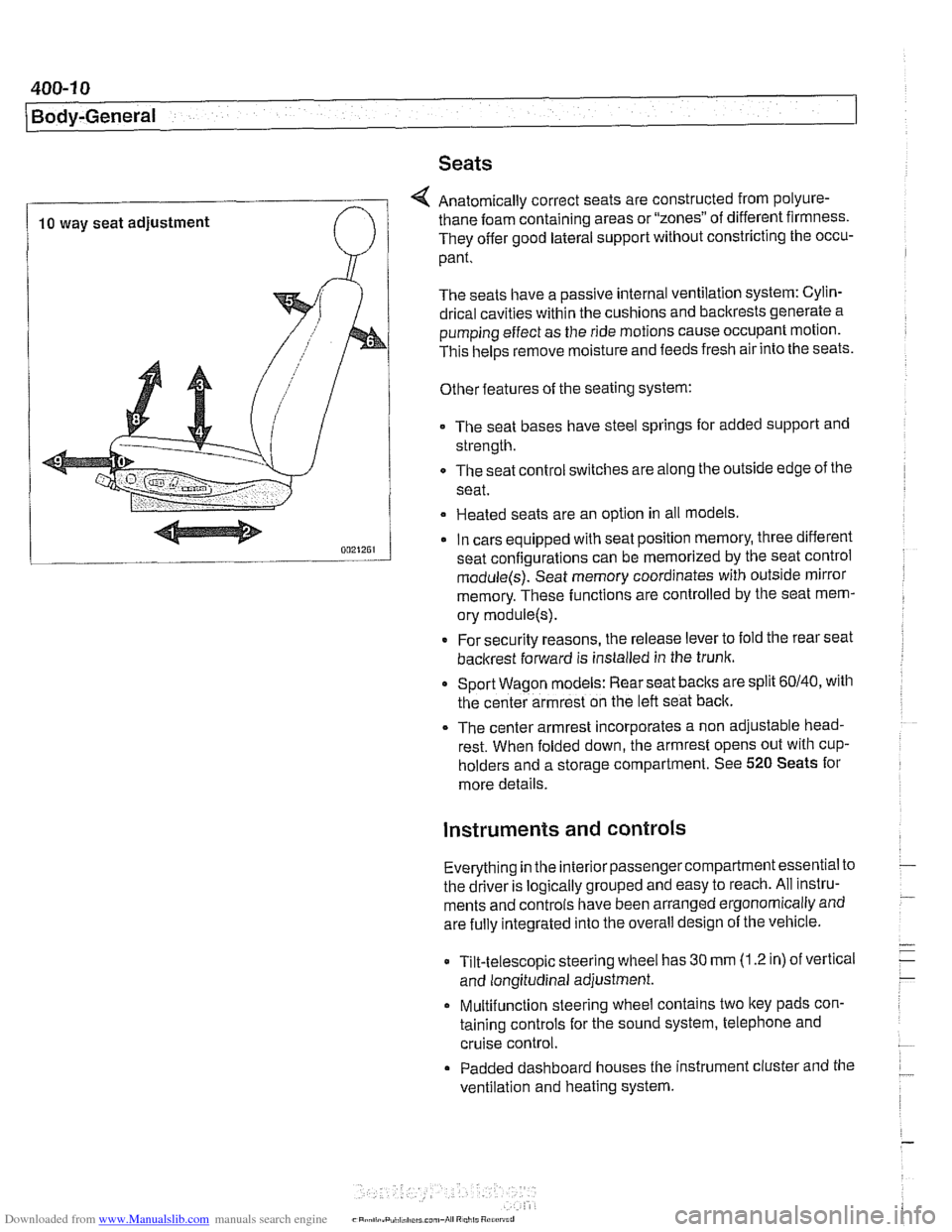
4 Anatomically correct seats are constructed from polyure-
10 way seat adjustment thane foam
containing areas or "zones" of different firmness.
They offer good lateral support without constricting the occu-
pant.
The seats have a passive internal ventilation system: Cylin-
drical cavities within the cushions and backrests generate a
pumping effect as the ride motions cause occupant motion.
This
helps remove moisture and feeds fresh air into the seats.
Other features of the seating system:
The seat bases have steel springs for added support and
strength.
The seat control switches are along the outside edge of
the
seat.
Heated seats are an option in all models
In cars equipped with seat position memory, three different
seat confiaurations can be memorized by the seat control
module(s): Seat memory coordinates with outside mirror
memory. These functions are controlled by the seat mem-
ory
module(s).
* For security reasons, the release lever to fold the rear seat
backrest forward is installed in the trunk.
Sport Wagon models: Rear seat
baclts are split 60140, with
the center armrest on the left seat back.
The center armrest incorporates a non adjustable head-
rest. When folded down, the armrest opens out with
cup-
holders and a storage compartment. See 520 Seats for
more details.
instruments and controls
Everything in the interior passengercompartment essential to
the driver is logically grouped and easy to reach. All instru-
ments and controls have been arranged ergonomically and
are fully integrated into the overall design of the vehicle.
Tilt-telescopic steering wheel has
30 mm (1.2 in) of vertical
and longitudinal adjustment.
Multifunction steering wheel contains two
ltey pads con-
taining controls for the sound system, telephone and
cruise control.
Padded dashboard houses the instrument cluster and the
ventilation and heating system.
Page 805 of 1002
Downloaded from www.Manualslib.com manuals search engine
Instrument cluster
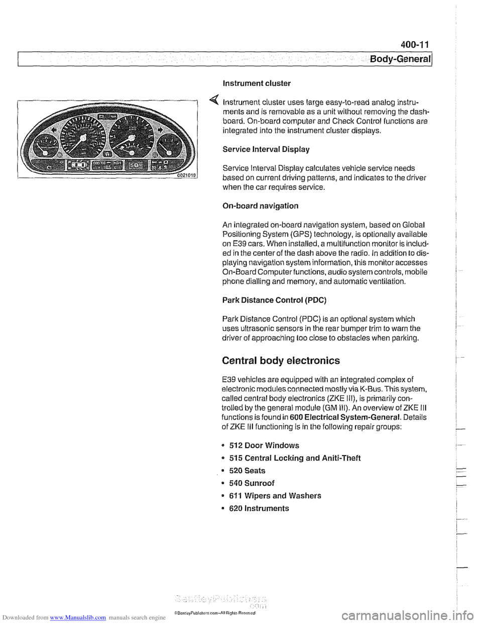
Instrument cluster uses large easy-to-read analog instru-
ments and is removable as a unit without removing the dash-
board. On-board computer and Check Control functions are
integrated into the instrument cluster displays.
Service Interval Display
Service Interval Display calculates vehicle service needs
based on current driving patterns, and indicates to the driver
when the car requires
service
On-board navigation
An integrated on-board navigation system, based on Global
Positioning System (GPS) technology, is optionally available
on
E39 cars. When installed, a multifunction monitor is includ-
ed in the center of the dash above the radio. in addition to dis-
playing navigation system information, this monitor accesses
On-Board Computerfunctions, audiosystem controls, mobile
phone dialling and memory, and automatic ventilation.
Park Distance Control (PDC)
Park Distance Control (PDC) is an optional system which
uses ultrasonic sensors in the rear bumper trim to warn the
driver of approaching too close to obstacles when parlting.
Central body electronics
E39 vehicles are equipped with an integrated complex of
electronic modules connected mostly via K-Bus. This system,
called central body electronics (ZKE
Ill), is primarily con-
trolled by the general module (GM
Ill). An overview of ZKE Ill
functions is found in 600 Electrical System-General. Details
of ZKE
Ill functioning is in the following repair groups:
- 512 Door Windows
* 515 Central Locking and Aniti-Theft
520 Seats
a 540 Sunroof
611 Wipers and Washers
620 Instruments
Page 809 of 1002
Downloaded from www.Manualslib.com manuals search engine
41 0-3
Fenders, Engine ~oodl
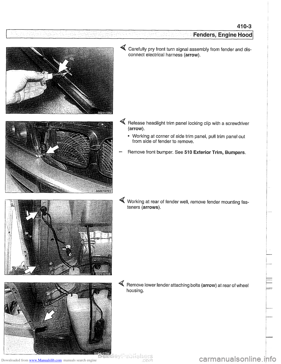
Carefully pry front turn signal assembly from fender and dis-
connect electrical harness (arrow).
< Release headlight trim panel locking clip with a screwdrivel
(arrow).
* Working at corner of side trim panel, pull trim panel out
from side of fender to remove.
- Remove front bumper. See 510 Exterior Trim, Bumpers.
Working at rear of
teners (arrows). fender
well, , remove
fender
'mounting fas-
< Remove lower
housing. 'attaching
bolts
(arrow) at rear of wheel
Page 814 of 1002
Downloaded from www.Manualslib.com manuals search engine
41 0-8
(Fenders, Engine Hood
Hood, aligning
When installing the hood, align the hinges as close to the orig-
inal painted surface as possible. Movement of the hood on its
attaching hardware may require touch-up paint.
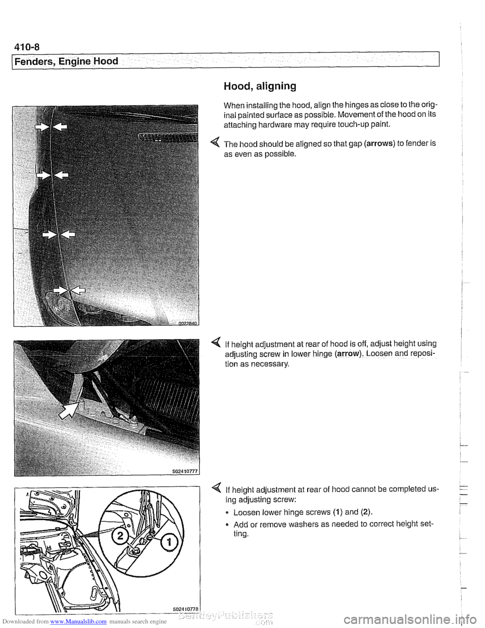
The hood should be aligned so that gap
(arrows) to fender is
as even as possible.
4 If height adjustment at rear of hood is off, adjust height using
adjusting screw in lower hinge
(arrow). Loosen and reposi-
tion as necessary.
If height adjustment at
ing adjusting screw: rear
of
hood cannot be completed us-
Q Loosen lower hinge screws (1) and (2).
Add or remove washers as needed to correct height set-
ting.
Page 819 of 1002
Downloaded from www.Manualslib.com manuals search engine
General ........................... .41 1.2 Door hinge adjustment ................ 41 1-5
Door hinge assembly
.................. 41 1-6 Doors ............................. 411-2
Front or rear door. removing
Door Panels ....................... 41 1-7
and installing ....................... .41 1.2 Door trim panel. removing and installing ... 41 1-7
Door check. replacing
................. .41 1.4 Sill trim panels ...................... 41 1-1 0
Page 820 of 1002
Downloaded from www.Manualslib.com manuals search engine
Doors
This repair group covers front and rear door repair informa-
tion. It includes removal and installation of front and rear
doors and trim panels.
For information on
airbag removal and installation, see 721
airbag.
For information on the power door windows and door glass
replacement, see
512 Door Windows.
For information on the power door
loclting system, see 515
Central Locking and Anti-Theft.
WARNING-
E39 cars are fitted with side-impact airbags in the front doors
and optional side impact
airbags in the rear doors. When
servicing doors, always disconnect the negative
(-) battery
terminal. See
721 Airbag System (SRS) for cautions and
procedures
relatinq to the airbaq system.
Front or rear door, removing and installing
- Disconnect negative (-) battery cable.
Prior to disconnecting the battery, read the battery discon-
nection cautionsgiven in
001 General Cautions and warn-
ings.
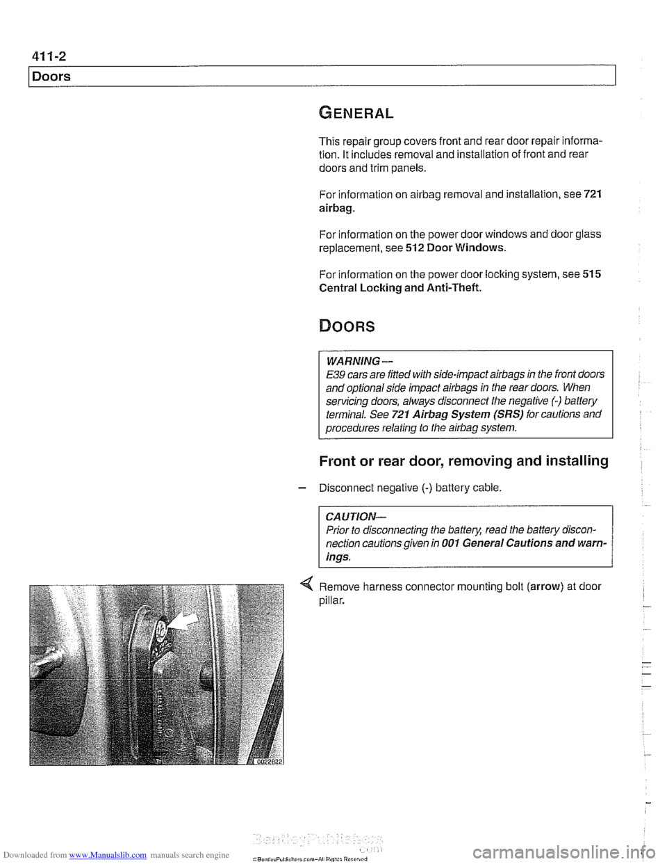
Remove harness connector mounting bolt (arrow) at door
pillar.
Page 821 of 1002
Downloaded from www.Manualslib.com manuals search engine
411-3
Doors
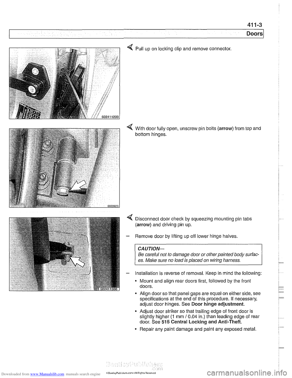
4 Pull up on locking clip and remove connector.
4 With door fully open, unscrew pin bolts (arrow) from top and
bottom hinges.
Disconnect door
check by squeezing mounting pin tabs
(arrow) and driving pin up.
Remove door by lifting up off lower hinge halves.
CAUJION-
Be careful not to damage door or otherpainted body surfac-
es.
Make sure no load is placed on wirinq harness.
Installation is reverse of removal. Keep in mind the following:
Mount and align rear doors first, followed by the front
doors.
Align door so that panel gaps are equal on either side, see
specifications at the end of this procedure. If necessary,
adjust door hinges. See Door hinge adjustment.
* Adjust door striker so that trailing edge of front door is
slightly higher
(I mm 10.04 in.) than leading edge of rear
door. See
515 Central Locking and Anti-Theft.
Repair any paint damage and paint any exposed metal.
Page 822 of 1002
Downloaded from www.Manualslib.com manuals search engine
Doors
~obr adjustment
Front fender to
4.25 mm i 0.25 mm (0.17 i- 0.01 in)
front door gap
Front
door to 4.5 mm i 0.25 mm (0.18 i 0.01 in)
rear door gap
Rear door to rear fender 4.0 mm i 0.25 mm (0.16 i 0.01 in)
Permissible deviation 1 .O mm (0.04 in)
from
~arallel
Tightening torque
Door hinge to door frame
20 Nm (15 it-lb)
Door check, replacing
WARNING -
E39 cars are fitted with side-impact airbags in the front doors
and optional side impact
airbags in the rear doors. When
servicing doors, always disconnect the negative
(-) battery
terminal. See
721 Airbag System (SRS) for cautions and
procedures relating to the
airbag system.
- Close door window completely.
- Disconnect negative (-) battery cable.
CAUTION-
Prior to disconnecting the batter)! read the battery discon-
nection cautions given in
001 General Cautions and
Warnings.
- Remove interior door panel. See Door trim panels, remov-
ing and installing.
- Where applicable, remove side-impact airbag from door. See
721 Airbag System (SRS). Remove door vapor barrier.
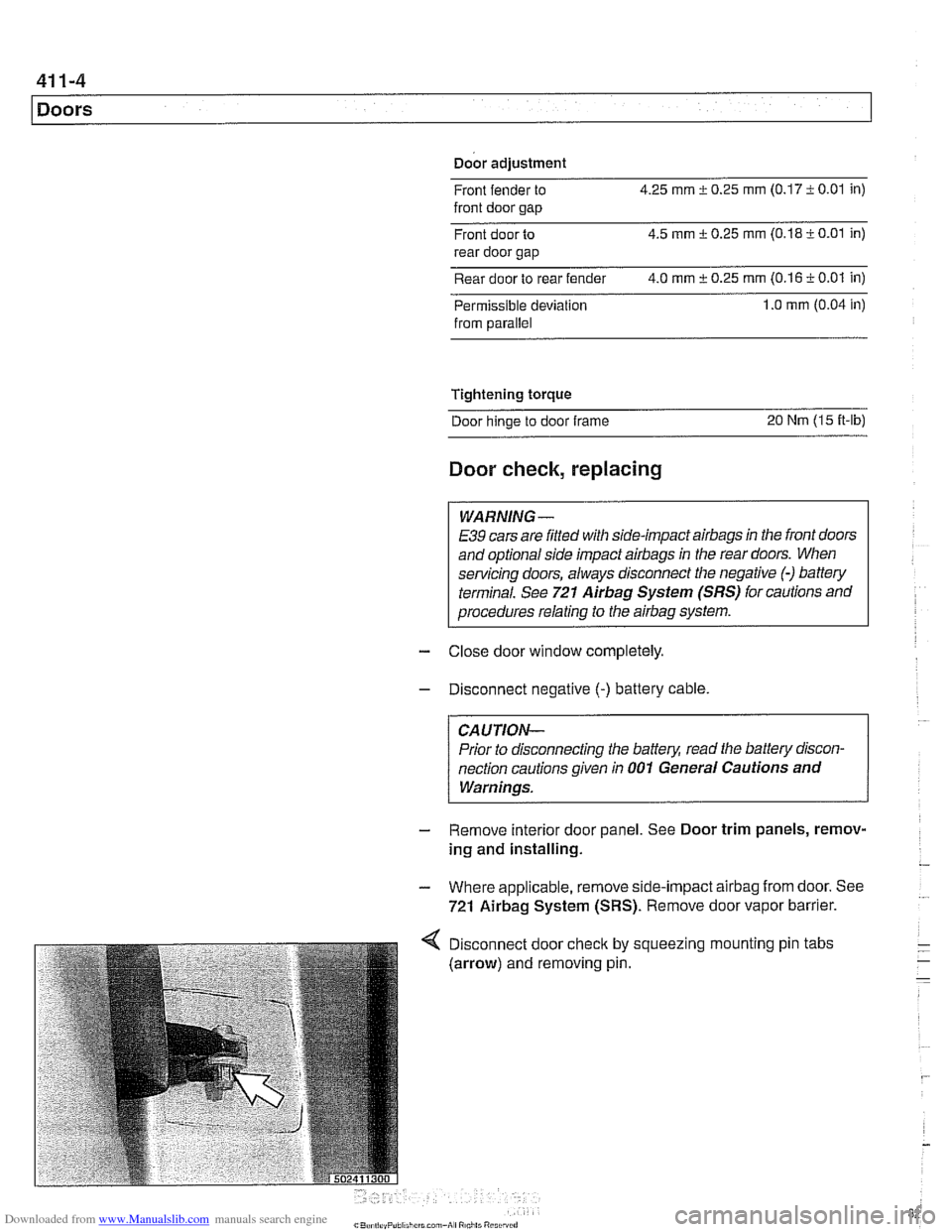
Disconnect door
check by
(arrow) and removing pin. squeezing I mounting
pin tabs
Page 823 of 1002
Downloaded from www.Manualslib.com manuals search engine
... -
Doors
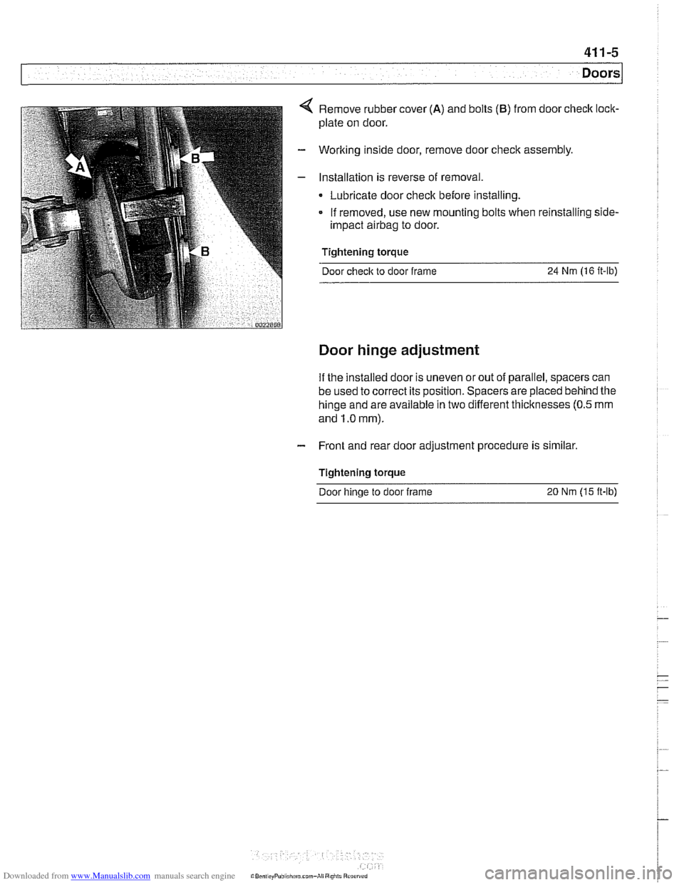
Remove rubber cover (A) and bolts (B) from door check lock-
plate on door.
Worlting inside door, remove door check assembly
Installation is reverse of removal.
Lubricate door check before installing.
- If removed, use new mounting bolts when reinstalling side-
impact airbag to door.
Tightening torque
Door
check to door frame 24 Nm (16 it-lb)
Door hinge adjustment
If the installed door is uneven or out of parallel, spacers can
be used to correct its position. Spacers are placed behind the
hinge and are available in two different thicltnesses
(0.5 mm
and 1.0 mm).
- Front and rear door adjustment procedure is similar.
Tightening torque Door hinge to door
frame 20 Nrn (15 ft-lb)