replace timing chain BMW 525i 1999 E39 Workshop Manual
[x] Cancel search | Manufacturer: BMW, Model Year: 1999, Model line: 525i, Model: BMW 525i 1999 E39Pages: 1002
Page 110 of 1002
Downloaded from www.Manualslib.com manuals search engine
113-16
Cylinder Head Removal and Installation
- Remove secondary timing chain and sprockets:
Remove mounting nuts from front of intake camshaft
sprocket. Remove and label shim.
CAUTION-
Hold the camshaft stationary (at hex on camshaft) when loos-
ening or tightening sprocket mounting fasteners.
Remove mounting nuts from front of exhaust camshaft
sprocket and remove and label thrust washer.
NOTE-
Where applicable, make note of thrust washerpositions. The
thicker
(0.4 mm) washer is mounted outermost.
- Remove secondary sprockets together with camshaft tim-
ing chain from front of camshafts.
CAUTION-
The camshafts must be locledin the TDCposition using the
special service tool as described earlier: The arrows on the
sprockets should not be used to accurately set the engine to
TDC. The tool holds the camshafts parallel to each other and
NOTE-
Do not remove the sprocl
to
Iceep the sproclefs timed to each other:
CAUTIOI\C
The crankshaft must not be allowed to rotate once the cam-
shaft timing chain is removed. The pistons can
contact the
valves.
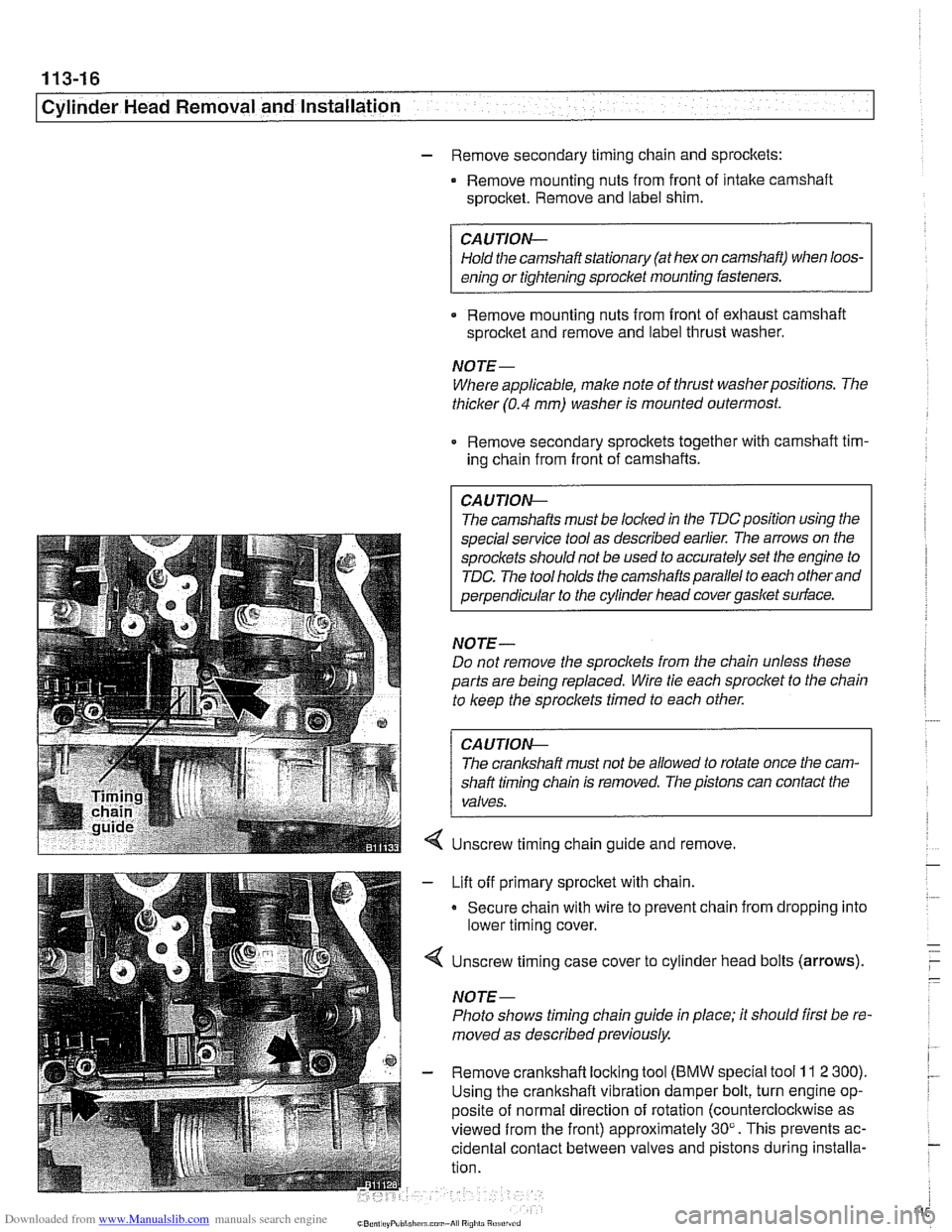
Unscrew timing chain guide and remove.
Lift off primary sprocket with chain.
Secure chain with wire to prevent chain from dropping into
lower timing cover.
Unscrew timing case cover to cylinder head bolts (arrows).
NOTE-
Photo shows timing chain guide in place; it should first be re-
moved as described previously.
Remove crankshaft locking tool
(BMW special tool 11 2 300).
Using the crankshaft vibration damper bolt, turn engine op-
posite of normal direction of rotation (counterclocltwise as
viewed from the front) approximately 30". This prevents ac-
cidental contact between valves and pistons during installa-
tion.
Page 112 of 1002
Downloaded from www.Manualslib.com manuals search engine
I Cylinder Head Removal and Installation
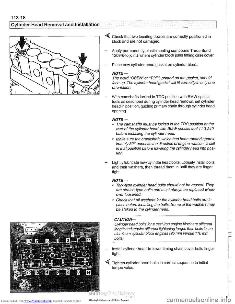
4 Check that two locating dowels are correctly positioned in
block and are not damaged.
- Apply permanently elastic sealing compound Three Bond
1209 8 to joints where cylinder block joins timing case cover.
- Place new cylinder head gasket on cylinder block.
NOTE-
The word "OBEN" or 'TOP': printed on the gasket, should
face up. The cylinder head
gasket will fit correctly in only one
orientation.
- With camshafts locked in TDC oosition with BMW soecial
tools as described during cylinder head removal,
seicylinder
head in position, guiding primary chain through cylinder head
opening.
NOTE-
* The camshafts must be locl(ed in the TDC position at the
rear of the cylinder head with
BMW special tool I1 3 240
before installing the cylinder head.
Make sure the
cranksha% which had been rotated approx-
imately
30" opposite the direction of engine rotation, is still
in that position before lowering the cylinder head into posi-
tion.
- Lightly lubricate new cylinder head bolts. Loosely install bolts
and their washers, then thread them in until they are finger
tight.
NOTE-
. Torx-type cylinder head bolts should not be reused. They
are stretch-type bolts and must always be replaced when-
ever loosened.
Check that all washers for the cylinder head bolts are in
place before installing the bolts. Some of the washers may
be
stalced to the cylinder head.
CAUTIOI\C
Cylinder head bolts for a cast iron engine block are different
length and require different tightening torque than bolts for an
aluminum cylinder bloclc engines
(95 rnm versus 110 rnm
bolts).
- Install cylinder head-to-lower timing chain cover bolts finger
tight.
< Tighten cylinder head bolts in correct sequence to initial
torque value.
Page 113 of 1002
Downloaded from www.Manualslib.com manuals search engine
I Cylinder Head Removal and Installation I
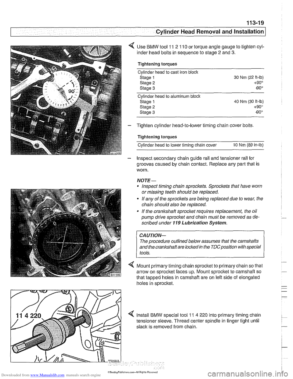
< Use BMW tool 11 2 110 or torque angle gauge to tighten cyl-
inder head bolts in sequence to stage
2 and 3.
Tightening torques
Cylinder head to cast iron
bloclc
Staoe 1
staie 2
Stage 3
Cyllnder head to aiumlnum block
Stage
1 40 Nm (30 it-lb)
Stage 2 +90°
Staoe 3 -80"
- Tighten cylinder head-to-lower timing chain cover bolts.
Tightening torques
cylinderhead to lower timing chain cover 10 Nm (89 in-lb)
- Inspect secondary chain guide rail and tensioner rail for
grooves caused by chain contact. Replace any part that is
worn.
NOTE-
Inspect timing chain sprocl(ets. Sprockets that have worn
or missing teeth should be replaced.
* If any of the sprockets are being replaced due to wear, the
chain should also be replaced.
If the crankshaft sproclet requir?s replacement, the oil
pump drive sprocket and chain must be removed as de-
scribed under
119 Lubrication System.
The procedure outlined below assumes that the camshafts
and the
cranl(shaft are locledin the TDCposition with special
4 Mount primary timing chain sprocltet to primary chain so that
arrow on sprocket faces up. Mount sprocket to camshaft so
that tapped holes in camshaft are on left side of elongated
holes in sprocltet
Install BMW special tool
1 I 4 220 into primary timing chain
tensioner sleeve. Thread center spindle in finger tight
until
slack is removed from chain.
Page 127 of 1002
Downloaded from www.Manualslib.com manuals search engine
- -
-- .- Cylinder ~ead~ernoval and Installation I - -.
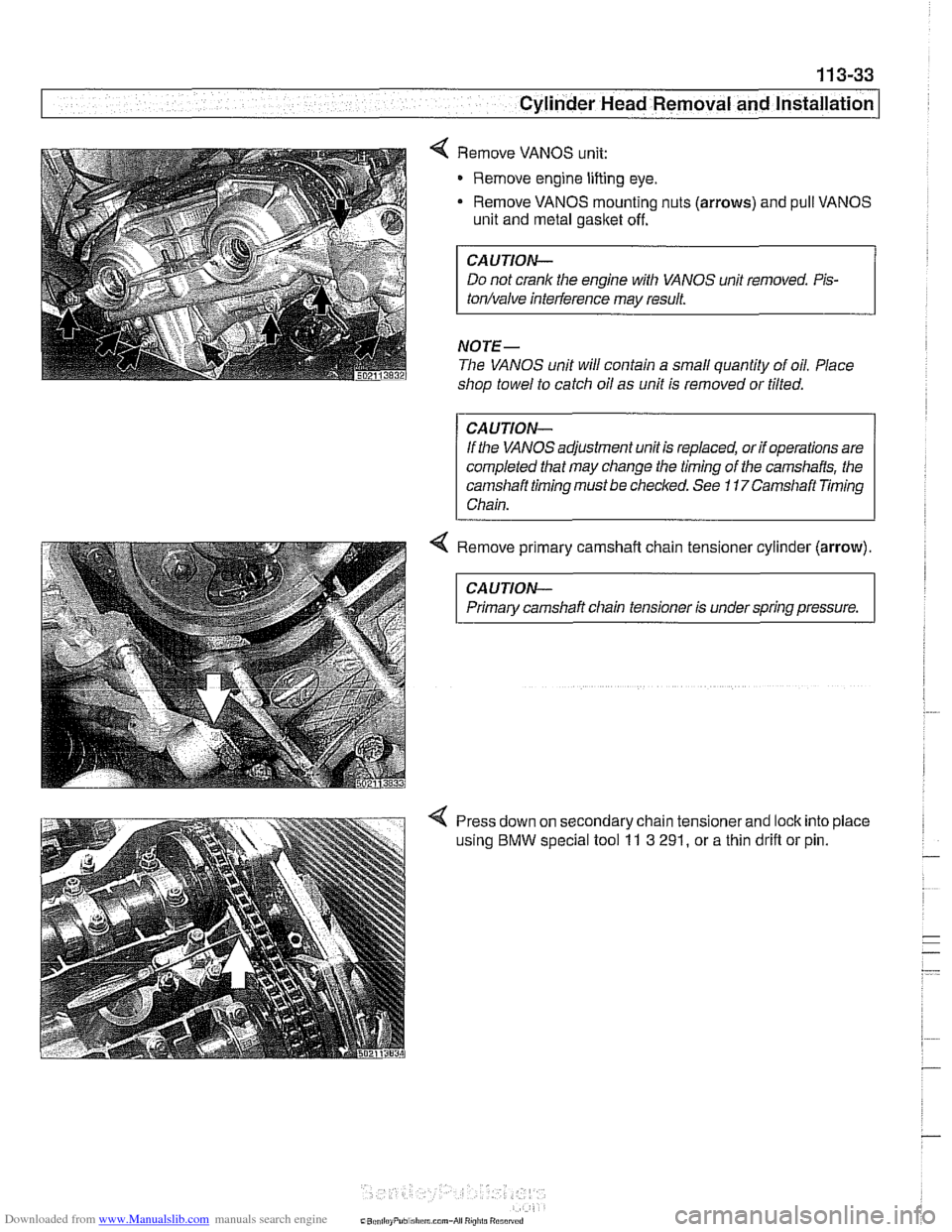
Remove VANOS unit:
Remove engine lifting eye.
- Remove VANOS mounting nuts (arrows) and pull VANOS
unit and metal gasket off.
CAUTION-
Do not crank the engine with VANOS unit removed. Pis-
tonhalve inteiference may result.
NOTE-
The VANOS unit will contain a small quantity of oil. Place
shop towel to catch oil as unit is removed or tilted.
CAUTION-
If the VANOS adjustment unit is replaced, or if operations are
completed that may change the timing of
the camshafts, the
camshaft timing must be checked. See
11 7Camshaft Timing
Chain.
4 Remove primary camshaft chain tensioner cylinder (arrow).
CAUTION-
Primary camshaft chain tensioner is under spring pressure.
Press down on secondary chain tensionerand lock into place
using
BMW special tool 11 3 291, or a thin drifl or pin.
Page 134 of 1002
Downloaded from www.Manualslib.com manuals search engine
11 3-40
I Cylinder Head Removal and Installation
Lubricate camshafts, camshaft carriers, bearing caps, hy-
draulic lifters, friction washers, splined shafts and spline hubs
with assembly lubricant before installation.
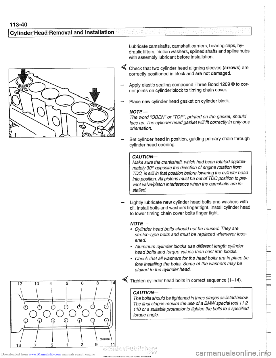
4 Check that two cylinder head aligning sleeves (arrows) are
correctly positioned in block and are not damaged.
- Apply elastic sealing compound Three Bond 1209 8 to cor-
ner joints on cylinder block to timing chain cover.
- Place new cylinder head gasket on cylinder block.
NOTE-
The word "OBEN" or "TOP printed on the gasket, should
face up. The cylinder headgaslet will fit correctly in only one
orientation.
- Set cylinder head in position, guiding primary chain through
cylinder head opening.
CAUJION-
Make sure the crankshaft, which had been rotated approxi-
mately 30" opposite the direction of engine rotation from
TDC, is still in thatposition before lowering the cylinder head
into position. All pistons must be out of TDC position to pre-
vent
valve/piston interference when the camshafts are in-
stalled.
- Lightly lubricate new cylinder head bolts and washers with
oil. Install bolts and washers finger tight. Install cylinder head
to lower timing chain cover bolts finger tight.
NOJE-
Cylinder head bolts should not be reused. They are
stretch-type bolts and must be replaced whenever loos-
ened.
* Aluminum cylinder blocls use different length cylinder
head bolts and torque values than cast iron blocks.
Check that all washers for
Nle head bolts are in place be-
fore installing the bolts. Some of the washers may be
staked to the cylinder head.
I 12 10 4 2 6 8 141 Tighten cylinder head bolts in correct sequence (1-14)
CA U TIOW-
The bolts should be tightened in three stages as listed below
The final stages require the use of a BMW special tool
11 2
110 or a suitable protractor to tighten the bolts to a specified
torque angle.
Page 147 of 1002
Downloaded from www.Manualslib.com manuals search engine
Cylinder Head Removal and Installation /
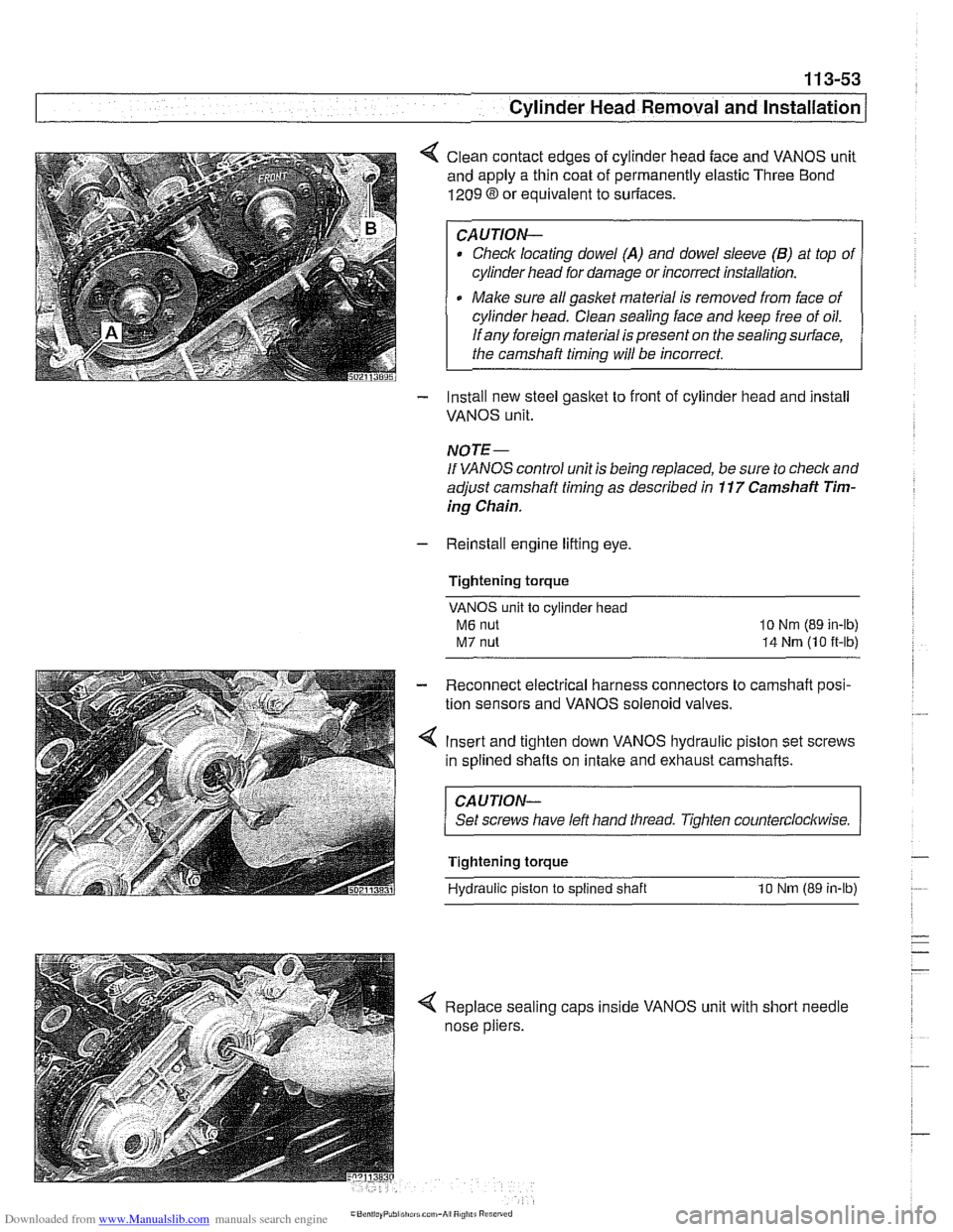
< Clean contact edges of cylinder head face and VANOS unit
and apply a thin coat of permanently elastic Three Bond
1209 8 or equivalent to suriaces.
CAUTION-
Check locating dowel (A) and dowel sleeve (B) at top of
cylinder head for damage or incorrect installation.
Make sure all gasket material is removed from face of
cylinder head. Clean sealing face and keep free of oil.
If any foreign material is present on the sealing surface,
the camshaft timing will be incorrect.
- Install new steel gasket to front of cylinder head and install
VANOS unit.
NOTE -
If VANOS control unit is being replaced, be sure to check and
adjust camshaft timing as described in
11 7 Camshaft Tim-
ing Chain.
- Reinstall engine lifting eye.
Tightening torque
VANOS unit to cylinder head
M6 nut
M7 nut
lo Nm (89 in-lb)
14 Nrn (10 it-lb)
- Reconnect electrical harness connectors to camshaft posi-
tion sensors and VANOS solenoid valves.
4 Insert and tighten down VANOS hydraulic piston set screws
in splined shafts on
intake and exhaust camshafts.
CAUJION-
Set screws have left hand tliread. Tighten counterclockwise.
Tightening torque
Hydraulic piston
to splined shaft 10 Nm (89 in-lb)
< Replace sealing caps inside VANOS unit with short needle
nose pliers.
Page 148 of 1002
Downloaded from www.Manualslib.com manuals search engine
. ." ".
[Cylinder Head Removal and Installation - .. - -1 -
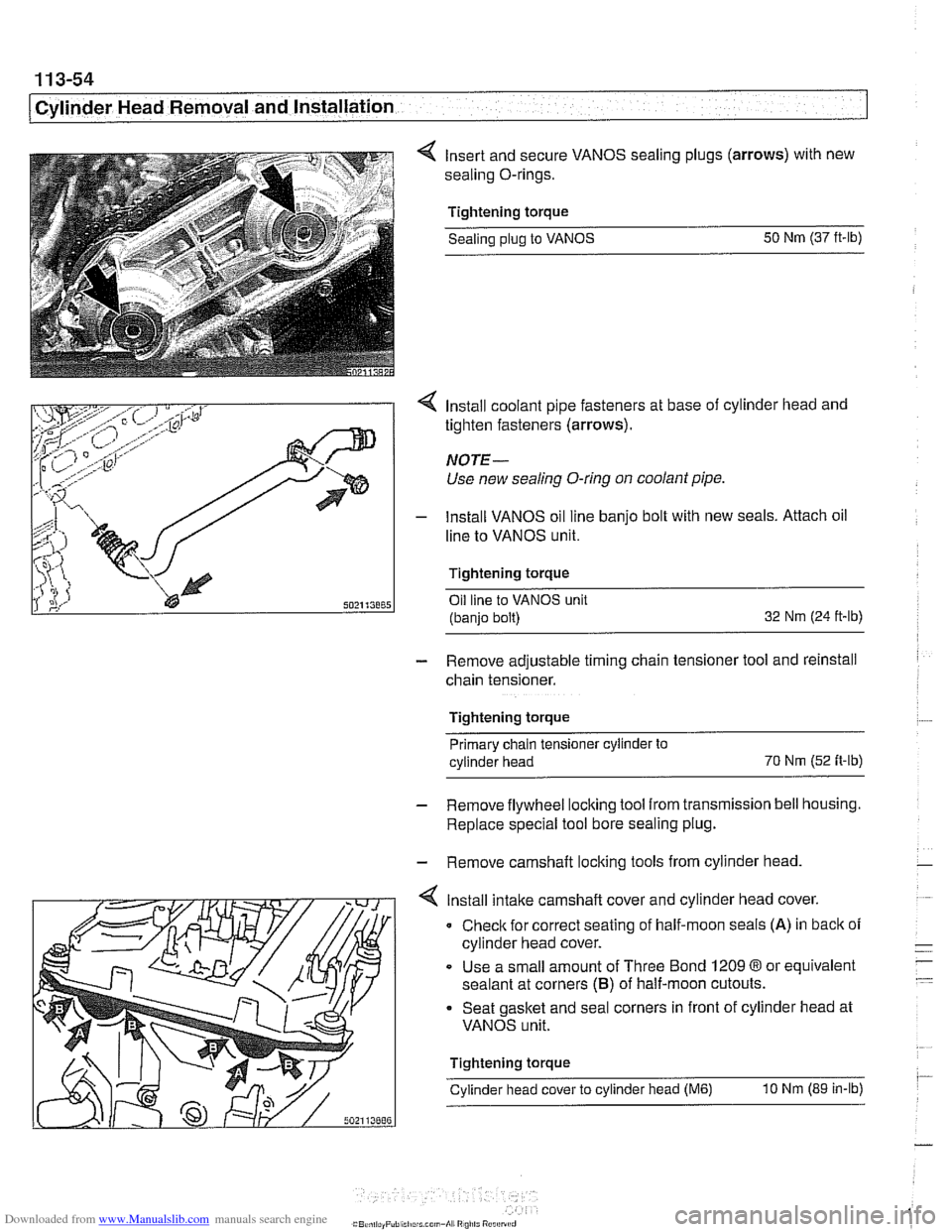
4 Insert and secure VANOS sealing plugs (arrows) with new
sealing O-rings.
Tightening torque Sealing
plug to VANOS 50
Nm (37 ft-lb)
4 Install coolant pipe fasteners at base of cylinder head and
tighten fasteners (arrows).
NOTE-
Use new sealing O-ring on coolant pipe.
- lnstall VANOS oil line banjo bolt with new seals. Attach oil
line to VANOS unit.
Tightening torque Oil line to VANOS unit
(banjo bolt) 32
Nm (24 ft-ib)
- Remove adjustable timing chain tensioner tool and reinstall
chain tensioner.
Tightening torque Primary chain tensioner cylinder to
cylinder head 70
Nm
(52 fi-ib)
- Remove flywheel locking tool from transmission bell housing.
Replace special tool bore sealing plug.
- Remove camshaft locking tools from cylinder head
4 lnstall intake camshaft cover and cylinder head cover.
0 Check for correct seating of half-moon seals (A) in back of
cylinder head cover.
Use a small amount of Three Bond
1209 8 or equivalent
sealant at corners
(B) of half-moon cutouts.
Seat gasket and seal corners in front of cylinder head at
VANOS unit.
Tightening torque
Cylinder head cover to cylinder head
(M6) 10 Nm (89 in-lb)
Page 175 of 1002
Downloaded from www.Manualslib.com manuals search engine
Cylinder Head Removal and Installation 1
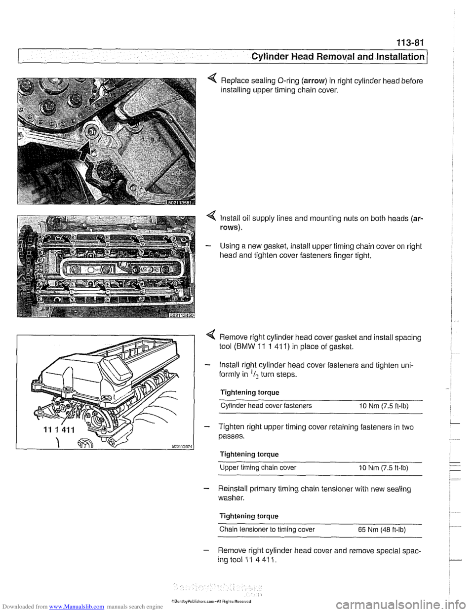
Replace sealing O-ring (arrow) in right cylinder head before
installing upper timing chain cover.
4 Install oil supply lines and mounting nuts on both heads (ar-
rows).
- Using a new gasket, install upper timing chain cover on right
head and tighten cover fasteners finger tight.
4 Remove right cylinder head cover gasket and install spacing
tool
(BMW 11 1 41 1) in place of gasket.
- Install right cylinder head cover fasteners and tighten uni-
formly in
'1, turn steps.
Tightening torque Cylinder head cover fasteners
10 Nm (7.5 ft-lb)
- Tighten right upper timing cover retaining fasteners in two
passes.
I Tightening torque
Upper timing chain cover
10 Nm (7.5 ft-lb)
- Reinstall primary timing chain tensioner with new sealing
washer.
Tightening torque
Chain tensioner to timing cover
65 Nm (48 ft-lb)
- Remove right cylinder head cover and remove special spac-
ingtooi 11 4411.
Page 181 of 1002
Downloaded from www.Manualslib.com manuals search engine
11 6-5
I Cylinder Head and valvetrain1
4 Timing chain tensioner bracket (V-8)
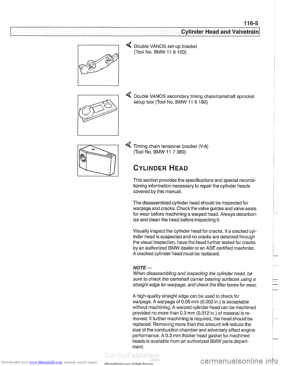
(Tool No. BMW
11 7 380)
CYLINDER HEAD
This section provides the specifications and special recondi-
tioning information necessary to repair the cylinder heads
covered by this manual.
The disassembled cylinder head should be inspected for
warpage and cracks. Check the valve guides and valve seats
for wear before machining a warped head. Always decarbon-
ize and clean the head before inspecting it.
Visually inspect the cylinder head for craclts.
If a cracked cyl-
inder head is suspected and no
craclts are detected through
the visual Inspection, have the head further tested for cracks
by an authorized BMW dealer or an ASE certified machinist.
A cracked cylinder head must be replaced.
NOJE-
When disassembling and inspecting the cylinder head, be
sure to
checlc the camshaft carrier bearing surfaces using a
straight edge for
warpage, and check the lifter bores for wear.
A high-quality straight edge can be used to
checlc for
warpage. A warpage of 0.05 mm (0.002 in.) is acceptable
without machining. A warped cylinder head can be machined
provided no more than 0.3
mm (0.012 in.) of material is re-
moved.
If further machining is required, the head should be
replaced. Removing more than this amount will reduce the
size of the combustion chamber and adversely affect engine
performance. A 0.3 mm
thicker head gasket for machined
heads is available from an authorized BMW parts depart-
ment.
Page 213 of 1002
![BMW 525i 1999 E39 Workshop Manual Downloaded from www.Manualslib.com manuals search engine
-
. - - -- Cylinder Head and valvetrain]
Turn engine over twice in direction of rotation until cylinder 1
intake and exhaust camshaft BMW 525i 1999 E39 Workshop Manual Downloaded from www.Manualslib.com manuals search engine
-
. - - -- Cylinder Head and valvetrain]
Turn engine over twice in direction of rotation until cylinder 1
intake and exhaust camshaft](/img/1/2822/w960_2822-212.png)
Downloaded from www.Manualslib.com manuals search engine
-
. - - -- Cylinder Head and valvetrain]
Turn engine over twice in direction of rotation until cylinder 1
intake and exhaust camshaft lobes (arrows) face each other.
- Lock crankshaft in TDC position with BMW special tool
11 2 300.
4 Place BMW special tool set 11 3 240 over camshafts and
measure clearances.
NOTE-
@ If the exhaust side of the tool (A) is not flush with the head,
camshaft timing is incorrect. Reset camshaft timing as de-
scribed in 11
7 Camshaft Timing Chain.
Due to flexible sprocket design, VANOS unit tolerances
and play in the VANOS splines, when the camshaft timing
is set correctly, the intake side of special tool set
11 3 240
(B) may be up to 1 mm (0.04 in.) above the suiface of the
cylinder head. This is normal. Reassemble engine. Other-
wise, reset camshaft timing as describedin 1
l?Camshaft
Timing Chain.
- Remove BMW special tool 11 6 150 from front of cylinder
head.
4 Clean contact edges of cylinder head face and VANOS unit
and apply a thin coat of Three Bond
12090 or equivalent
sealing compound to surfaces.
CAUTION-
Male sure all gasket material is removed from face of cyl-
inder head. Clean sealing face and keep free of oil.
Check locating dowel
(A) and dowel sleeve (B) at top
of cylinder head for damage or incorrect installation.
- Using a new steel gasket, install VANOS unit to front of cyi-
inder head. See 117 Camshaft Timing Chain.
NOTE-
If VANOS control unit is being replaced, be sure to check and
adjust camshaft timing as described in 117 Camshaft Tim-
ing Chain.
- Reinstall engine lifting eye.
- Reconnect electrical harness connectors to camshaft posi-
tion sensors and
VANOS solenoid valves.