replace timing chain BMW 525i 1999 E39 Owner's Manual
[x] Cancel search | Manufacturer: BMW, Model Year: 1999, Model line: 525i, Model: BMW 525i 1999 E39Pages: 1002
Page 279 of 1002
Downloaded from www.Manualslib.com manuals search engine
Camshaft Timing Chain
- Connect electrical harness connectors to camshaft position
sensors and VANOS solenoid valves.
- Remove BMW special locking tools from rear of cylinder
head.
- Remove cranltshaft locking tool and replace sealing plug.
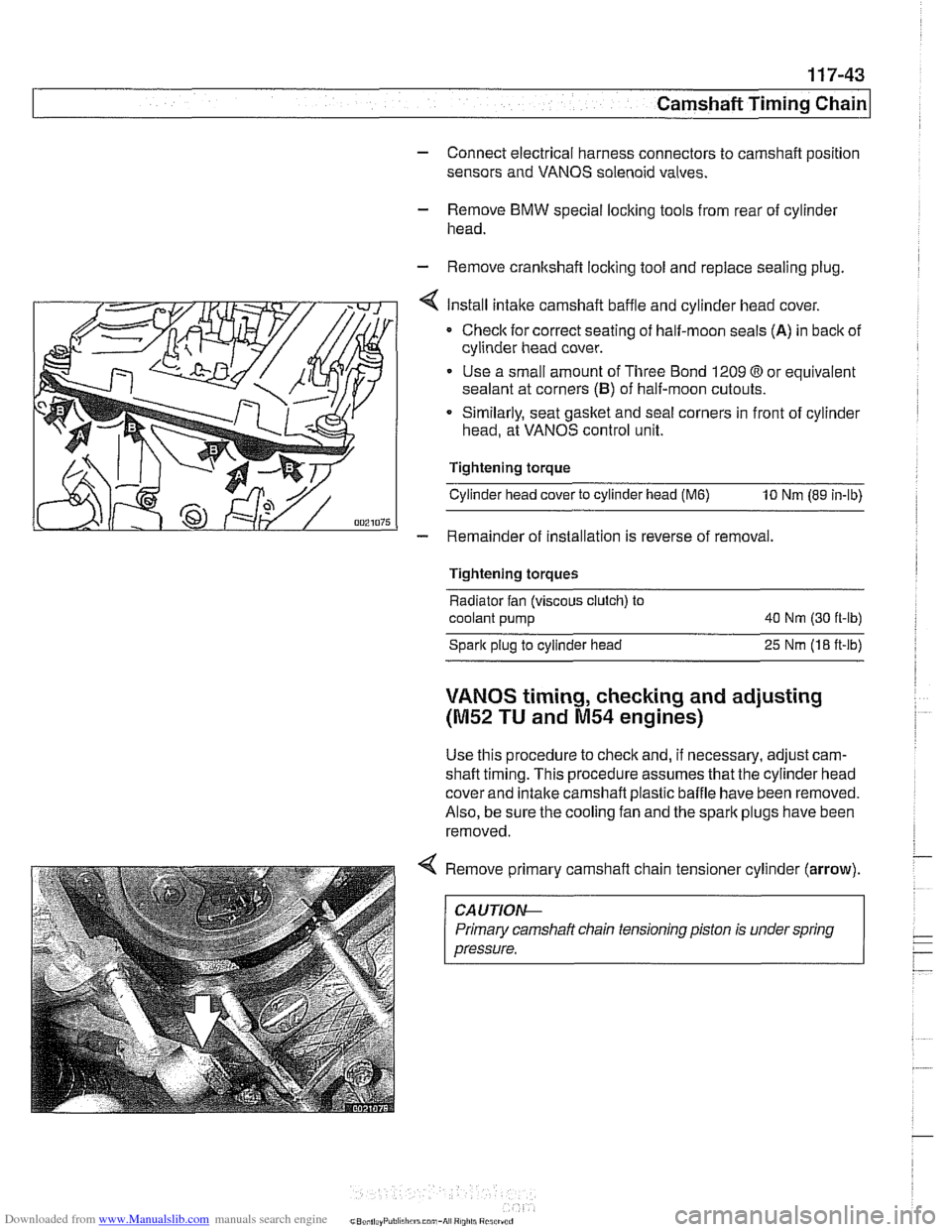
Install intake camshaft baffle and cylinder head cover.
Checlc for correct seating of half-moon seals (A) in back of
cylinder head cover.
Use a small amount of Three Bond 1209
O or equivalent
sealant at corners
(B) of half-moon cutouts.
Similarly, seat gasket and
seal corners in front of cylinder
head, at VANOS control unit.
Tightening torque
Cylinder head cover to cylinder head
(M6) 10 Nm (89 in-lb)
- Remainder of installation is reverse of removal.
Tightening torques
Radiator fan (viscous clutch) to
coolant pump 40
Nm (30 ft-lb)
Spark plug to cylinder head
25 Nrn (18 ft-lb)
VANOS timing, checking and adjusting
(M52 TU and M54 engines)
Use this procedure to check and, if necessary, adjust cam-
shaft timing. This procedure assumes that the cylinder head
cover and intake
camshaft plastic baffle have been removed.
Also, be sure the cooling fan and the spark plugs have been
removed.
Remove primary camshaft chain tensioner cylinder
(arrow).
~~ ~ ~~ ~--~
CA UTlOAC
Primary camshaft chain tensioning piston is under spring
pressure.
Page 292 of 1002
Downloaded from www.Manualslib.com manuals search engine
~ ~~ ~
I Camshaft Timing Chain I --
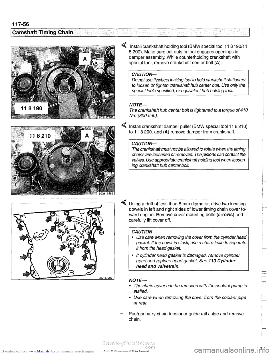
lnstall crankshaft holding tool (BMW special tool 11 8 190/11
8 200). Make sure cut outs in tool engages openings in
damper assembly. While counterholding crankshaft with
special tool, remove crankshaft center bolt (A).
CAUTION-
Do not use flywheel locking tool to hold crankshaft stationary
NOTE-
The crankshaft hub centerbolt is tightened to a torque of 410
Nm (300 ft-lb).
4 Install crankshaft damper puller (BMW special tool 11 8 210)
to 11 8 200. and (A) remove damper from crankshaft.
The crankshaft must not be allowed to rotate when the timing
chains are loosened or removed. The pistons can contact the
valves. Use appropriate crankshaft holding tool when loosen-
ing crankshaft hub center bolt.
Using a drift of less than
5 mm diameter, drive two locating
dowels in left and right sides of lower timing
cham cover to-
ward engine. Remove cover mounting bolts
(arrows) and
carefully lift cover off.
CA
UTION-
* Use care when removing the cover from the cylinder heao
gasket. If the cover is stuck, use a sharp
knife to separate
it from the headgasket.
If cylinder liead gasket Is damaged, remove cylinder
head and replace head gasket. See
113 Cylinder
head and valvetrain.
NOTE-
- The chain cover can be removed with the coolant pump in-
stalled.
Use care when removing the cover from the coolant pipe
at rear.
- Push primary chain tensioner guide rail aside and remove
chain.
Page 293 of 1002
Downloaded from www.Manualslib.com manuals search engine
... -.
rpp- --- Camshaft Timing Chain1
Timing chains, installing
(M52 TU and M54 engines)
CAUTIOI\C
The procedure outlined below assumes that the camshaits
are lockedin the
TDC installation position with speciallocling
tools as shown earliel:
- inspect timing chain sprockets. Inspect guide rail and ten-
sioner rail for damage. Replace any part that is worn
or dam-
aged.
NOTE-
If any sprockets are being replaced due to wear, the chain
should also be replaced.
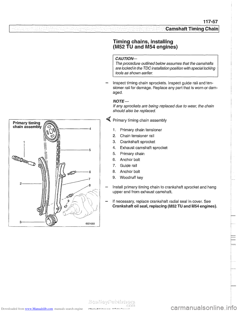
4 Primary timing chain assembly
1. Primary chain tensioner
2. Chain tensioner rail
3. Cranltshaft sprocket
4. Exhaust camshaft sprocket
5. Primary chain
6. Anchor bolt
7. Guide rail
8. Anchor bolt
9. Woodruff key
- Install primary timing chain to crankshaft sprocltet and hang
upper end from exhaust camshaft.
- If necessary, replace crankshaft radial seal in cover. See
Crankshaft oil seal, replacing (M52 TU and M54 engines).
Page 310 of 1002
Downloaded from www.Manualslib.com manuals search engine
I Camshaft Timina Chain
/ Cylinders 5-8
Timing chains, installing
(M62 engine to 911 998)
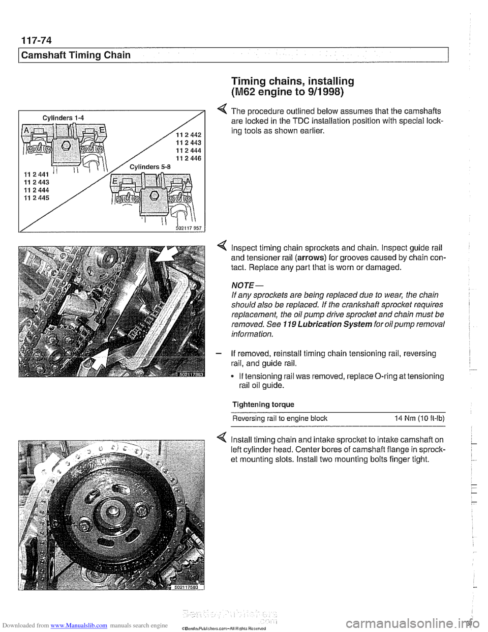
4 The procedure outlined below assumes that the camshafts
are locked in the TDC installation position with special lock-
ing tools as shown earlier.
4 lnspect timing chain sprocltets and chain. Inspect guide rail
and tensioner rail
(arrows) for grooves caused by chain con-
tact. Replace any part that is worn or damaged.
NOTE-
If any sprocl(ets are being replaced due to wear, the chain
should also be replaced.
If the crankshaft sprocket requires
replacement, the oil pump
drive sprocket and chain must be
removed. See
119 Lubrication System for oilpump removal
information.
- If removed, reinstall timing chain tensioning rail, reversing
rail, and guide rail.
If tensioning rail was removed, replace O-ring at tensioning
rail oil guide.
Tightening torque Reversing rail
to engine block 14 Nrn (10 n-lb)
4 lnstall timing chain and intalte sprocket to intake camshaft on
left cylinder head. Center bores of camshaft flange in sprock-
et mounting slots. Install two mounting bolts finger tight.
Page 311 of 1002
Downloaded from www.Manualslib.com manuals search engine
Camshaft Timing Chain1
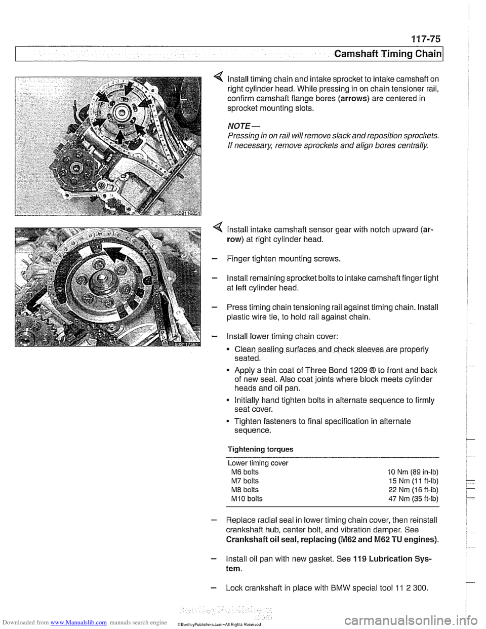
lnstall timing chain and intake sprocket to intake camshaft on
right cylinder head. While pressing in on chain tensioner rail,
confirm camshaft flange bores (arrows) are centered in
sprocket mounting slots.
NOTE-
Pressing in on rail will remove slack and reposition sprockets.
If
necessarx remove sproclets and align bores centrally.
lnstall intake camshaft sensor gear with notch upward (ar-
row) at right cylinder head.
- Finger tighten mounting screws.
- lnstall remaining sprocket bolts to intake camshaft finger tight
at left cylinder head.
- Press timing chain tensioning rail against timing chain. lnstall
plastic wire
tie, to hold rail against chain.
- lnstall lower timing chain cover:
Clean sealing surfaces and check sleeves are properly
seated.
Apply a thin coat of Three Bond 1209
8 to front and back
of new seal. Also coat joints where block meets cylinder
heads and oil pan.
Initially hand tighten bolts in alternate sequence to firmly
seat cover.
Tighten fasteners to final specification in alternate
sequence.
Tightening torques Lower timing cover
M6 bolts 10 Nrn (89 in-lb)
M7 bolts 15 Nm (1 1 ft-lb)
ME bolts 22 Nm (1 6 ft-lb)
M10 bolts 47 Nm (35 ft-lb)
- Replace radial seal in lower timing chain cover, then reinstall
crankshaft hub, center bolt, and vibration damper. See
Crankshaft oil seal, replacing
(M62 and M62 TU engines).
- lnstall oil pan with new gasket. See 119 Lubrication Sys-
tem.
- Lock crankshaft in place with BMW special tool 11 2 300
Page 313 of 1002
Downloaded from www.Manualslib.com manuals search engine
Camshaft Timing Chain
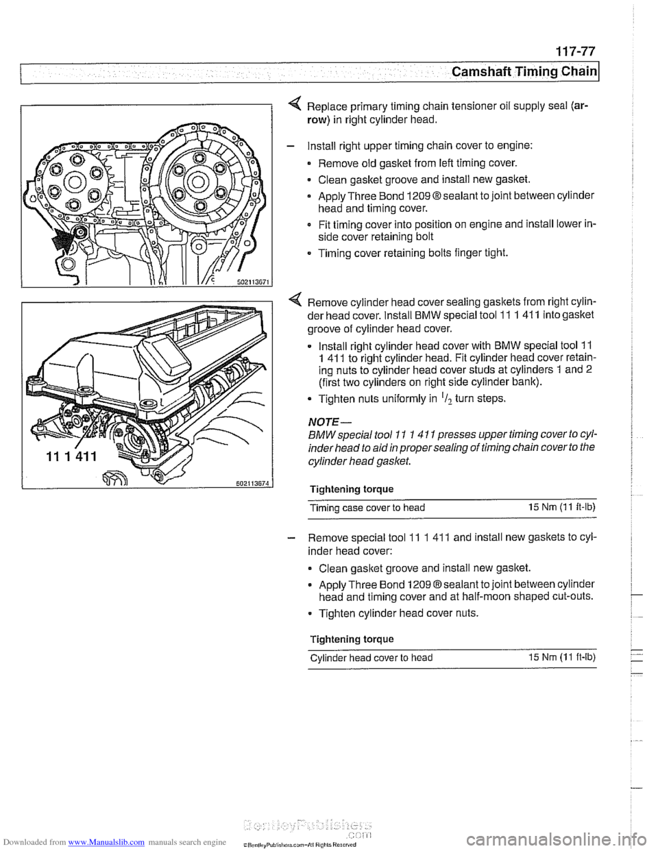
4 Replace primary timing chain tensioner oil supply seal (ar-
row) in right cylinder head.
- Install right upper timing chain cover to engine:
Remove old gasket from
left timing cover.
Clean gasket groove and install new gasket.
Apply Three Bond
1209Osealant to joint between cylinder
head and timing cover.
Fit timing cover into position on engine and install lower in-
side cover retaining bolt
Timing cover retaining bolts finger tight.
4 Remove cylinder head cover sealing gaskets from right cylin-
der head cover. Install
BMW special tool 11 1 41 1 into gasltet
groove of cylinder head cover.
Install right cylinder head cover with
BMW special tool 11
1 41 1 to right cylinder head. Fit cylinder head cover retain-
ing nuts to cylinder head cover studs at cylinders 1 and 2
(first two cylinders on right side cylinder bank).
Tighten nuts uniformly in
'Il turn steps.
NOTE-
BMW special tool 11 1 4 11 presses upper timing cover to cyl-
inder head to aid
in proper sealing of timing chain cover to the
cylinder head gasket.
Tightenlng torque
Timing case cover to head 15
Nm (1 1
It-lb)
- Remove special tool 11 1 41 1 and install new gaskets to cyl-
inder head cover:
Clean gasltet groove and install new gasltet.
Apply Three Bond 1209 Osealant to joint between cylinder
head and timing cover and at half-moon shaped cut-outs.
Tighten cylinder head cover nuts.
Tightenlng torque
-
Cylinder head cover to head 15 Nm (1 1 ft-lb)
Page 319 of 1002
Downloaded from www.Manualslib.com manuals search engine
Camshaft Timing chain/
- Tighten accessible sprocket retaining bolts in the following
order:
Leit exhaust camshaft
Right exhaust
camshait
Leit intake camshaft
Right
intalte camshait
Tightening torque
Sprocket bolts to camshaft flange
15 Nm (1 1 ft-lb)
- Remove BMW special tool 11 2 300 from tool bore at bell-
housing and remove
camshaft loclting tools from cylinder
heads.
Using crankshaft center bolt, turn engine over clockwise at
least one
comolete rotation so that remainino camshaft
sprocltet
retaking bolts are accessible. -
- Tighten remaining camshait sprocket retaining bolts
Tightening torque Sprocket bolts to camshaft
flange 15 Nm (I 1 It-lb)
- Remove BMW special tool 11 3 390 from primary timing
chain tensioner bore and reinstall primary chain tensioner
- Remainder of installation is reverse or removal, noting the fol-
lowing:
Remove gasket residue from cylinder head sealing sur-
face.
Apply a thin bead of Three Bond 1209
O sealing com-
pound to joints at cylinder head cover and timing case cov-
er and at half-moon sections at rear of cylinder heads.
Replace cylinder head cover
gaskets if necessary.
Page 516 of 1002
Downloaded from www.Manualslib.com manuals search engine
.," --
Radiator and Cooling System --- 1
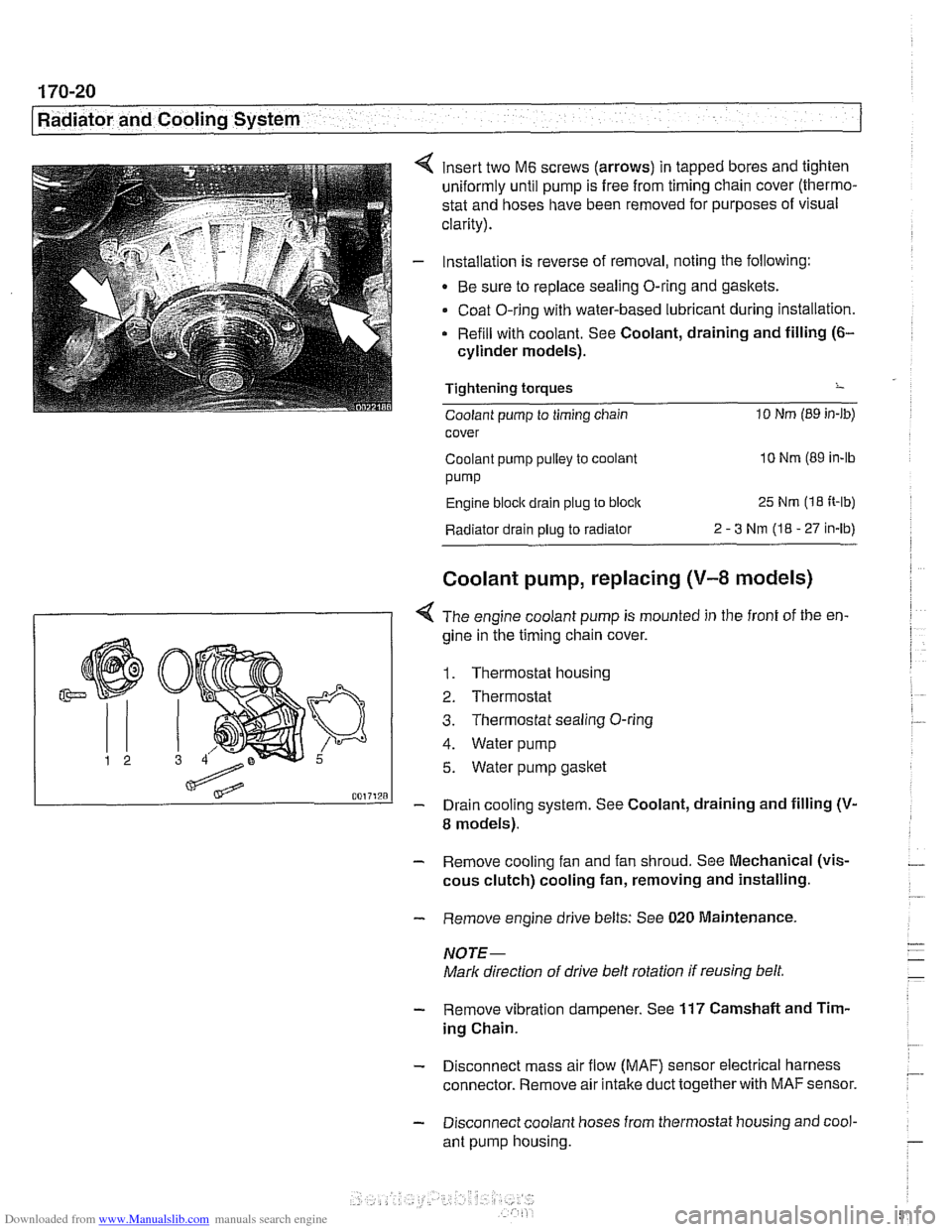
insert two M6 screws (arrows) in tapped bores and tighten
uniformly until pump is free from timing chain cover (thermo-
stat and hoses have been removed for purposes of visual
clarity).
Installation is reverse of removal, noting the following:
Be sure to replace sealing O-ring and gaskets.
Coat O-ring with water-based lubricant during installation.
Refill with coolant. See Coolant, draining and filling
(6-
cylinder models).
Tightening torques
-
Coolant pump to timing chain 10 Nm (89 in-lb)
cover
Coolant pump pulley to coolant
10 Nm (89 in-lb
pump
Engine block drain plug to block 25 Nm (1 8 It-lb)
Radiator drain plug to radiator 2 - 3 Nm (I8 - 27 in-lb)
Coolant pump, replacing (V-8 models)
I 1 < The engine coolant pump is mounted in the front of the en-
gine in ;he timing chain cover.
1. Thermostat housing
2. Thermostat
3. Thermostat sealing O-ring
4. Water pump
5. Water pump gasket
- Drain cooling system. See Coolant, draining and filling (V-
8 models).
- Remove cooling fan and fan shroud. See Mechanical (vis-
cous clutch) cooling fan, removing and installing.
- Remove engine drive belts: See 020 Maintenance.
NOTE-
Mark direction of drive belt rotation if reusing belt,
- Remove vibration dampener. See 117 Camshaft and Tim-
ing Chain.
- Disconnect mass air flow (MAF) sensor electrical harness
connector. Remove air intake duct together with
MAF sensor.
- Disconnect coolant hoses from thermostat housing and cool-
ant pump housing.
Page 992 of 1002
Downloaded from www.Manualslib.com manuals search engine
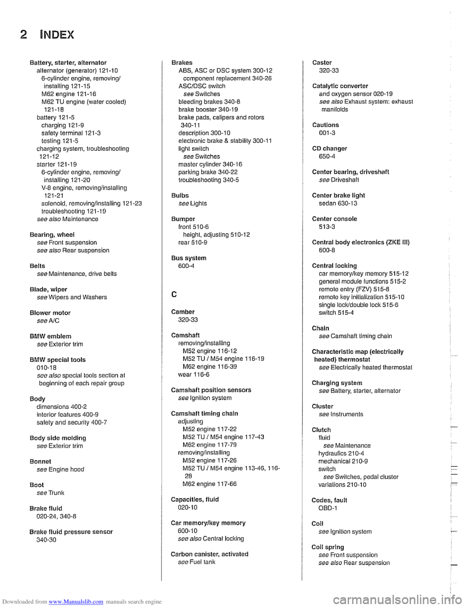
2 INDEX
Battery, starter, alternator
alternator (generator)
121-10
6-cylinder engine, removingi
installing 121-15
M62 engine 121-16
M62 TU engine (water cooled)
121-18
battery
121-5 charging 121-9
safety terminal 121-3
testing 121-5 charging system, troubleshooting
121-12
starter
121-1 9
6-cylinder engine, removingi instaliinq 121-20 . V-8 engine, rernovinglinsialiing
121-21
solenoid, removinglinstalling
121-23 troubleshooting 121-19
see also Maintenance
Bearing, wheel
see Front suspension
see also Rear suspension
Belts see Maintenance, drive belts
Blade, wiper
see Wipers and Washers
Blower motor see
A/C
BMW emblem
see Exterior trim
BMW special tools 010-18 see also special tools section at
beginning
of each repair group
Body dimensions 400-2
interior features
400-9 salety and security 400-7
Body side molding
see Exterior trim
Bonnet see Engine hood
Boot see Trunk
Brake fluid
020-24, 340-8
Brake fluid pressure sensor
340-30
Brakes
ABS, ASC or DSC system
300-12
component replacement 340-26
ASCIDSC switch
see Switches
bleeding
bralces 340-8
brake booster 340-1 9 bralce Dads. caiioers and rotors ,., 340-1 1
descriotion 300-10
e~ectrdnic brake & stability 300-11
light switch
see Switches
master cylinder
340-16 pariking brake 340-22
troubleshooting 340-5
Bulbs see Lights
Bumper
lront 510-6 height, adjusting 510-12
rear 510-9
Bus system
600-4
Camber
320-33
Camshaft
removingiinslaiiing
M52 engine 116-12
M52 TU
/ M54 engine 116-1 9 M62 engine 11 6-39
wear
116-6
Camshaft position sensors
see ignition system
Camshaft timing chain
adjusting M52 engine
117-22
M52 TU I M54 engine 117-43
M62 engine 117-79 removinglinstalling
M52 engine 117-26
M52TU 1 M54 engine 113-46.116-
28
M62 engine 117-66
Capacities, fluid
020.10
Car rnemorvlicev memorv . . 600-10
see also Centrai
lociking
Carbon canister, activated
see Fuel
tank
Caster
320-33
Catalytic converter and oxygen sensor 020-19
see also Exhaust system: exhaust
manilolds
Cautions
001-3
CD changer
650-4
Center bearing, driveshaft
see Driveshait
Center brake light
sedan
630-13
Center console
513-3
Centrai body electronics (ZKE 111)
600-6
Central locking
car memoryiey memory 515.12 general module iunctions 515-2
remote entry (FZV) 515-8
remote lkey initialization 515-10 single lociddouble ioclk 515-6
switch 515-4
Chain
see Camshaft liming chain
Characteristic map (electrically heated) thermostat
see Electrically heated thermostat
Charging system
see Battery, starter, alternator
Cluster see instruments
Clutch fluid see Maintenance
hydraulics
210-4
mechanical 210-9
switch
see Switches, pedal ciuster
variations
210.10
Codes, fault OED-1
Coil
see Ignition system
Coil spring
see Front suspension
see also Rear
suspe nsion