tow BMW 525i 1999 E39 Workshop Manual
[x] Cancel search | Manufacturer: BMW, Model Year: 1999, Model line: 525i, Model: BMW 525i 1999 E39Pages: 1002
Page 11 of 1002
Downloaded from www.Manualslib.com manuals search engine
01 0-1
010 General
General ........................... .01 0.2
How to Use this Manual ............ .01 0.2
Warnings. cautions and notes ........... .0l 0.3
Getting Started .................... .0i 0.5
Safety ............................. .O1 0.5
Lifting the car ........................ .O1 0.5
Raising car ......................... .O1 0.5
Working under car .................... .O1 0.6
Advice for the Beginner ............ .O1 0.7
Planning ahead ...................... .O1 0.7
Workshop practices ................... .O1 0.7
Non-reusable fasteners ................ .O1 0.7
Tightening fasteners .................. .O1 0.8
Gaskets and seals .................... .O1 0.9
Electrical testing .................... .O1 0.10
Wire repairs ........................ .O1 0.10
Buying Parts ..................... .01 0.11
Genuine BMW parts ................. .O1 0.11
Non-returnable parts ................. .O1 0.11
Information you need to know .......... .0l 0.12
Service ........................... 01 0-1 3
TOOIS ............................. 010-13
Basic tool requirements ............... 01 0-1 4
Jack stands ......................... 01 0-1 6
Oil change equipment ................. 01 0-1 6
Torque wrench ...................... 01 0-17
Digital multimeter .................... 010-17
BMW special tools ................... 01 0-1 8
Emergencies ...................... 01 0-1 8
Changing a tire ...................... 01 0-1 8
Jump starting ....................... 01 0-1 9
Indicator and warning lights ............ 01 0-1 9
Towing ............................ 010-20
Spare parts kit ...................... 010-21
Page 22 of 1002
Downloaded from www.Manualslib.com manuals search engine
01 0-1 2
1 General
Information you need to know
Model
When ordering parts it is important that you know the correct
model designation for your car. Models covered in this E39
manual are the
525i,5281,530i, 540i in Sedan and Station
Wagon body styles.
Model year
This is not necessarily the same as date of manufacture or
date of sale.
A 1999 model may have been manufactured in
late 1998, and perhaps not sold until early 2000. It is still a
1999 model. Model years covered by this manual are 1997 to
2002.
Date of manufacture
This information is necessary when ordering replacement
parts or determining if any of the warranty recalls are applica-
ble to your car. The label on the driver's door below the door
latch will specify the month and year that the car was built.
Vehicle
Identification Number (VIN)
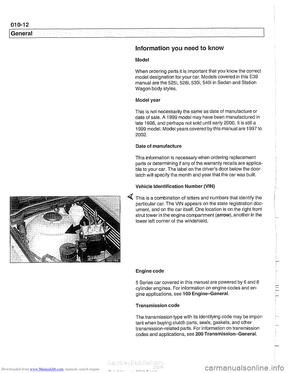
This is a combination of letters and numbers that identify the
particular car. The VIN appears on the state registration doc-
ument, and on the car itself. One location is on the right front
strut tower in the engine compartment (arrow), another in the
lower left corner of the windshield.
Engine code
5 Series car covered in this manual are powered by
6 and 8 - cylinderengines. For information on engine codes and en- -. -
gine applications, see 100 Engine-General. -
Transmission code
The transmission type with its identifying code may be
impor- :
tant when buying clutch parts, seals, gaskets, and other .- transmission-related parts. For information on transmission
codes and applications, see 200 Transmission-General.
Page 30 of 1002
Downloaded from www.Manualslib.com manuals search engine
01 0-20
General
more information on the Check Engine Light and the on-
board diagnostic system.
Towing
The cars covered by this manual should be towed with a tow
truck using wheel lift or flat bed equipment. Do not tow the car
on all four wheels except
forvery short distances to move it to
a safe place.
CA U JION-
Do not tow with sling-type equipment The front spoilers and
b~m~er covers may sustain damage.
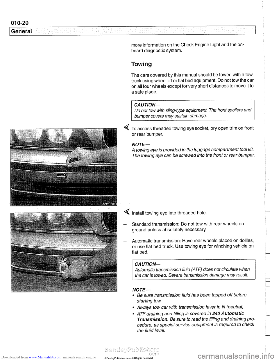
4 To access threaded towing eye socltet, pry open trim on front
or rear bumper.
NOJE-
A towing eye is provided in the luggage compartment tool lcit.
The towing eye can be screwed into the front or rear bumper.
4 Install towing eye into threaded hole.
- Standard transmission: Do not tow with rear wheels on
ground unless absolutely necessary.
- Automatic transmission: Have rear wheels placed on dollies,
or use flat bed truck. Use towing eye for winching vehicle on
flat bed.
CAUTION-
Automatic transmission fluid (ATF) does not circulate when
I the car is towed. Severe transmission damage may result.
NOTE-
Be sure transrnission fluid has been topped off before
starting tow.
Always tow car with transrnission lever in
N (neutral).
. ATF draining and filling is covered in 240 Automatic
Transmission.
Be sure to read the filling and draining pro.
cedure, as special service equipment is required to
checlc
the fluid level.
Page 63 of 1002
Downloaded from www.Manualslib.com manuals search engine
Maintenance
BODY AND INTERIOR MAINTENANCE
Body and hinges, lubricating
Door locksand loclccylinderscan be lubricated with an oil that
contains graphite.
Body and doorhinges, hood latch and doorcheclc rods should
be lubricated with
SAE 30 or SAE 40 engine oil. Lubricate
seat runners with multipurposegrease. Do not apply any oil to
rubber parts.
If door weather-strips are sticking, lubricate
them with silicone spray or talcum powder. The hood release
cable should be lubricated as well.
The use of winter
lock deicer sprays should be lkept to an
absolute minimum, as the alcohol in the deicer will wash the
grease out of the lock assemblies and may cause locks to
corrode internally or to become difficult to operate.
Exterior washing
The longer dirt is left on the paint, the greater the risk of dam-
aging theglossy finish,
eitherby scratching or by thechemical
effect dirt particles may have on the painted surface.
Do not wash the car in direct sunlight. If the engine hood is
warm, allow it to cool. Beads of water not only leave spots
when dried rapidly by the sun or heat from theengine, but also
can act as small magnifying glasses and burn spots into the
finish. Wash the car with a mixture of lukewarm water and a
car wash product. Rinse using plenty of clear water. Wipe the
body dry with a sofl cloth towel or chamois to prevent
water-spotting.
Interior care
Dirt spots can usually be removed with lultewarm soapy water
or a dry foam cleaner. Use spot remover for grease and oil
spots. Do not pour the liquid directly on the carpet or fabric,
but dampen a clean cloth and rub carefully, starting at the
edge of the spot and working inward. Do not use gasoline,
naphtha, or other flammable substances.
Leather upholstery and trim
Leather upholstery and trim should be periodically cleaned
using a slightly damp cotton or wool cloth. The idea is to get
rid of the dirt in the creases and pores that can cause brittle-
ness and premature aging. On heavily soiled areas, use a
mild detergent (such as
wooliteQ) or other specially formulat-
ed leather cleaners. Dry the trim and upholstery completely
Page 85 of 1002
Downloaded from www.Manualslib.com manuals search engine
Engine Removal and Installation
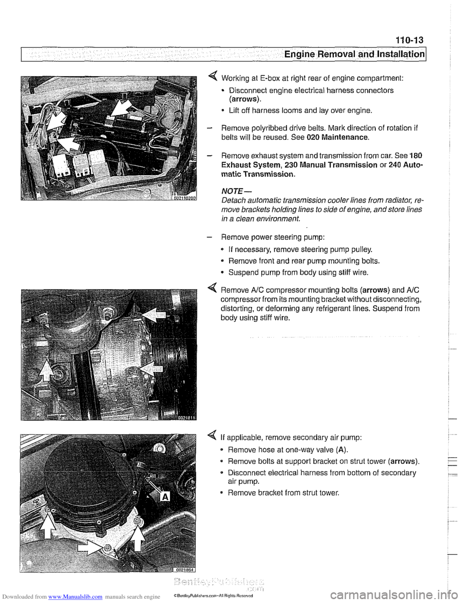
4 Working at E-box at right rear of engine compartment:
Disconnect engine electrical harness connectors
(arrows).
Lift off harness looms and lay over engine.
- Remove polyribbed drive belts. Mark direction of rotation if
belts will be reused. See 020 Maintenance.
- Remove exhaust system and transmission from car. See 180
Exhaust System, 230 Manual Transmission or 240 Auto-
matic Transmission.
NOJE-
Detach automatic transmission cooler lines from radiator, re-
move brackets holding lines to side of engine, andstore lines
in a clean environment.
- Remove power steering pump:
If necessary, remove steering pump pulley.
Remove front and rear pump mounting bolts.
Suspend pump from body using stiff wire.
4 Remove A/C compressor mounting bolts (arrows) and AIC
compressor from its mounting bracketwithoutdisconnecting,
distorting, or deforming any refrigerant lines. Suspend from
body using stiff wire.
4 If applicable, remove secondary air pump:
Remove hose at one-way valve
(A).
Remove bolts at support bracket on strut tower (arrows).
- Disconnect electrical harness from bottom of secondary
air pump.
Remove bracket from strut tower.
Page 93 of 1002
Downloaded from www.Manualslib.com manuals search engine
--
-- Engine Removal and installation' -
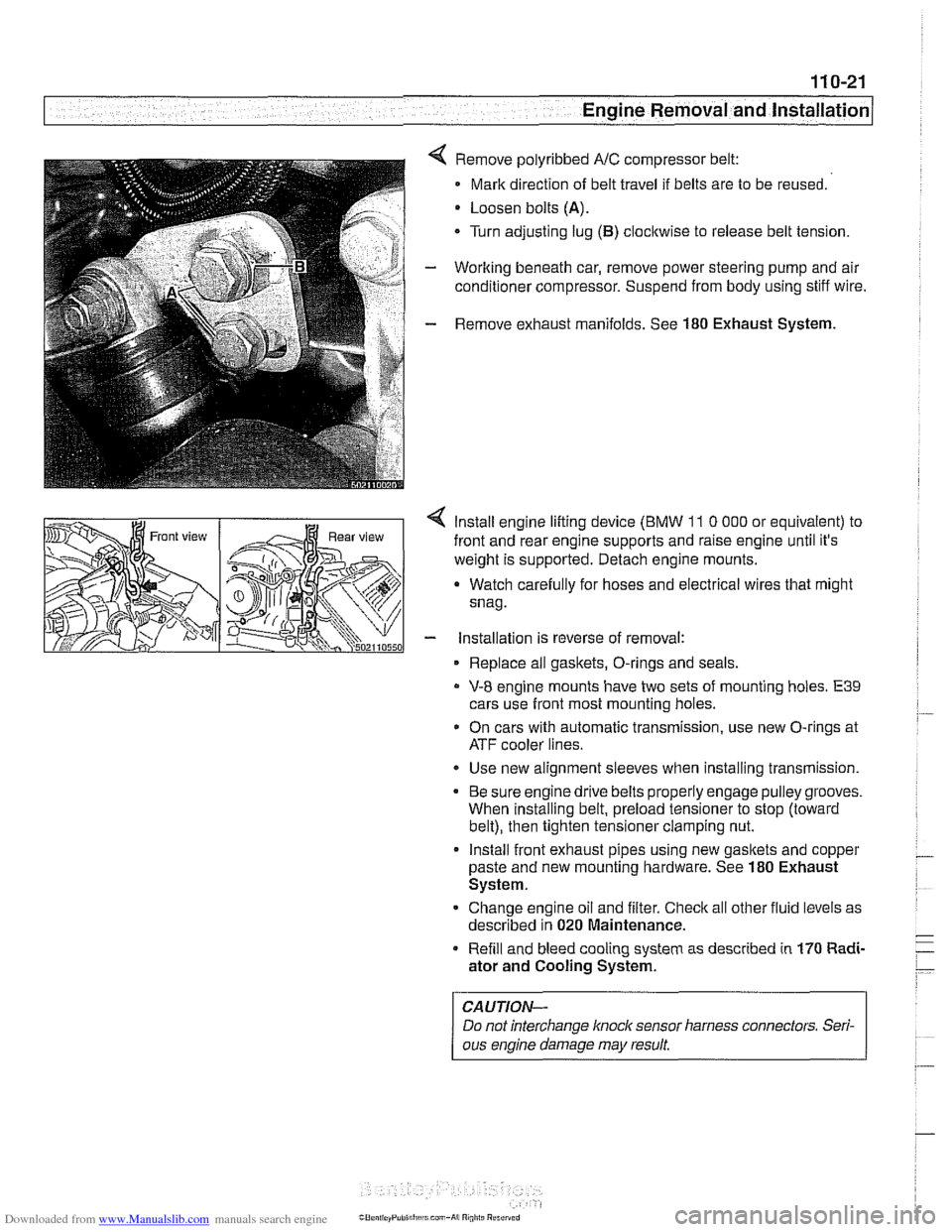
Remove polyribbed A/C compressor belt:
Mark direction of belt travel if belts are to be reused.
Loosen bolts
(A).
Turn adjusting lug (B) clocltwise to release belt tension.
Working beneath car, remove power steering pump and air
conditioner compressor. Suspend from body using stiff wire.
Remove exhaust manifolds. See
180 Exhaust System.
< lnstall engine lifting device (BMW 11 0 000 or equivalent) to
front and rear engine supports and raise engine until it's
weight is supported. Detach engine mounts.
a Watch carefully for hoses and electrical wires that might
snag.
- installation is reverse of removal:
Replace all gaskets, O-rings and seals.
V-8 engine mounts have two sets of mounting holes. E39
cars use front most mounting holes.
* On cars with automatic transmission, use new O-rings at
ATF cooler lines.
Use new alignment sleeves when installing transmission.
Be sure engine drive belts properly engage pulley grooves.
When installing belt, preload tensioner to stop (toward
belt), then tighten tensioner clamping nut.
lnstall front exhaust pipes using new gasltets and copper
paste and new mounting hardware. See
180 Exhaust
System.
Change engine oil and filter. Check all other fluid levels as
described in
020 Maintenance.
Refill and bleed cooling system as described in
170 Radi-
ator and Cooling System.
CAUTION-
Do not interchange knoclc sensor harness connectors. Seri-
ous engine damage may result
Page 118 of 1002
Downloaded from www.Manualslib.com manuals search engine
. .- -
Cylinder Head Removal and Installation
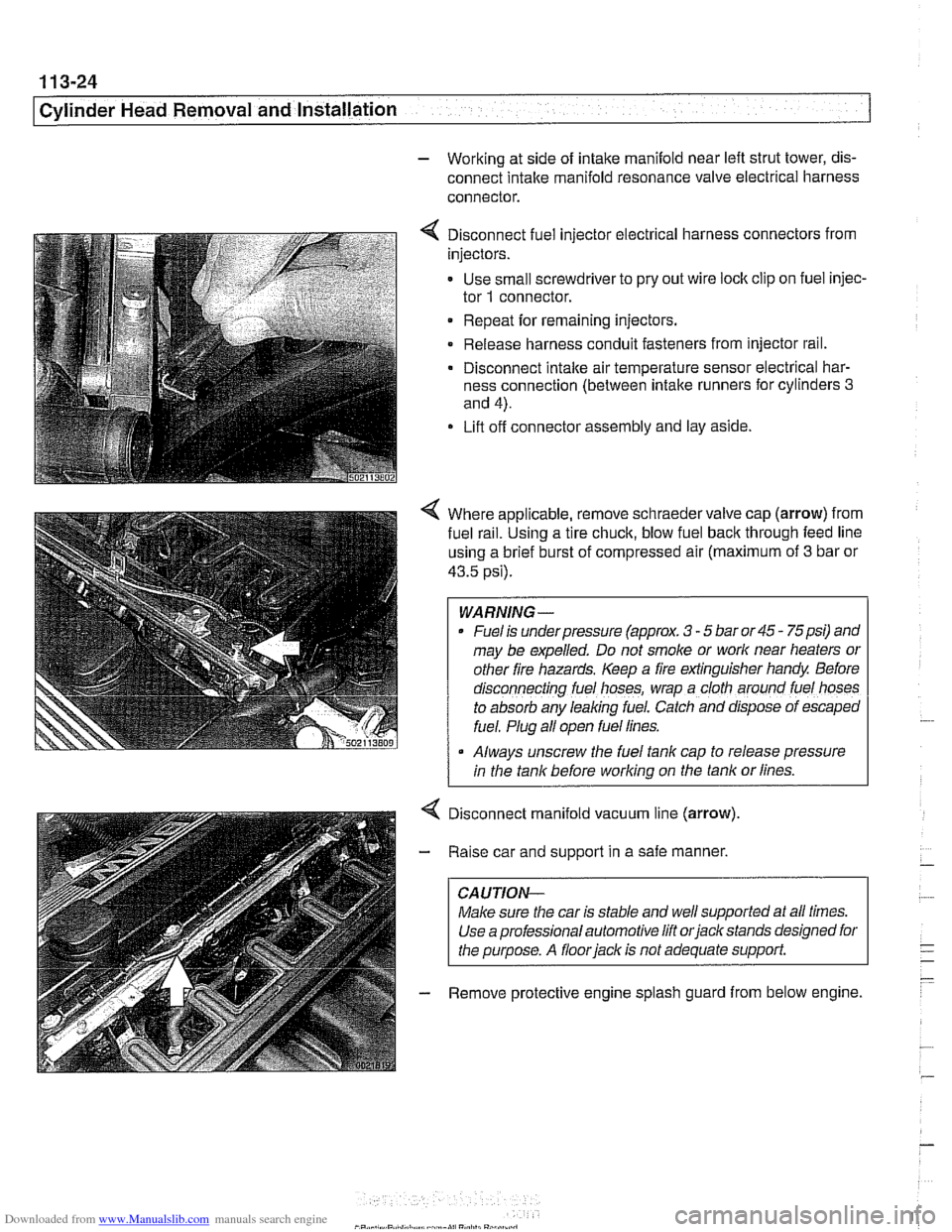
- Working at side of intake manifold near left strut tower, dis-
connect intake manifold resonance valve electrical harness
connector.
4 Disconnect fuel injector electrical harness connectors from
injectors.
- Use small screwdriver to pry out wire lock clip on fuel injec-
tor
1 connector.
Repeat for remaining injectors.
Release harness conduit fasteners from injector rail.
- Disconnect intake air temperature sensor electrical har-
ness connection (between intake runners for cylinders
3
and 4).
Lift off connector assembly and lay aside.
4 Where applicable, remove schraeder valve cap (arrow) from
fuel
ra~l. Using a tire chuck, blow fuel back through feed line
using a brief burst of compressed air (maximum of
3 bar or
43.5 psi).
WARNING-
Fuel is underpressure (approx. 3 - 5 bar or 45 - 75psi) and
may be expelled. Do not smoke or
work near heaters or
other fire hazards. Keep a fire extinguisher handy Before
d~sconnecting fuel hoses, wrap a cloth around fuel hoses
to absorb any leaking fuel. Catch and
dfspose of escaped
fuel. Plug all open fuel lines.
Always unscrew the fuel tank cap to release pressure
I in the tank before working on the tank or lines.
Disconnect manifold vacuum line (arrow)
Raise car and support in a safe manner,
CAUTION-
Make sure the car is stable and well supported at all times.
Use a professional automotive lift
orjack stands designed for
the purpose. A
floorjack is not adequate support.
Remove protective engine splash guard from below engine.
Page 123 of 1002
Downloaded from www.Manualslib.com manuals search engine
Cylinder Head Removal and Installation
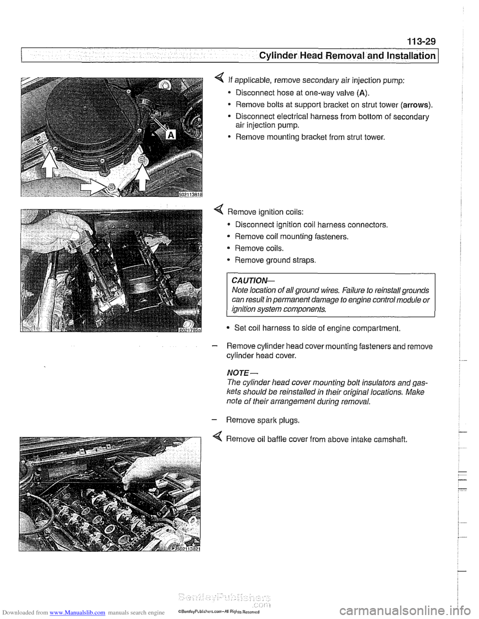
4 If applicable, remove secondary air injection pump:
Disconnect hose at one-way valve
(A).
Remove bolts at support bracket on strut tower (arrows).
Disconnect electrical harness from bottom of secondary
air injection pump.
Remove mounting bracket from strut tower.
4 Remove ignition coils:
* Disconnect ignition coil harness connectors.
Remove coil mounting fasteners.
Remove coils.
* Remove ground straps.
CA UTIOI\C
Note location of all ground wires. Failure to reinstall grounds
can result in permanent damage to engine control module or
ignition system components.
Set coil harness to side of engine compartment
- Remove cylinder head cover mounting fasteners and remove
cylinder head cover.
NOTE-
The cylinder head cover mounting bolt insulators and gas-
ltets should be reinstalled in their original locations. Male
note of their arrangement during removal.
- Remove spark plugs
4 Remove oil baffle cover from above intake camshaft.
Page 124 of 1002
Downloaded from www.Manualslib.com manuals search engine
Cylinder Head Removal and installation - - .- - - - -
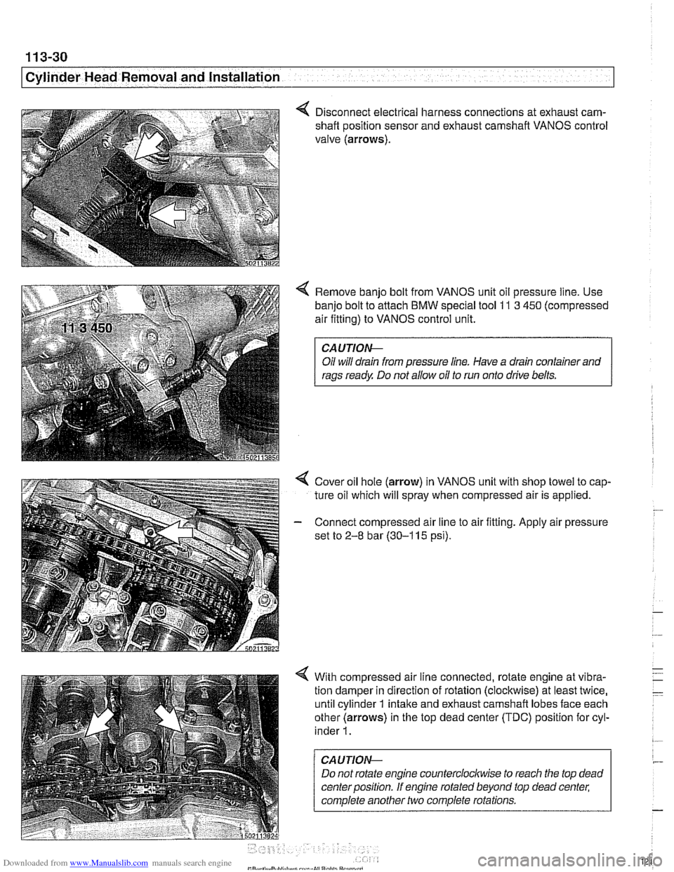
4 Disconnect electrical harness connections at exhaust cam-
shaft position sensor and exhaust camshaft VANOS control
valve (arrows).
4 Remove banjo bolt from VANOS unit oil pressure line. Use
banjo bolt to attach
BMW special tool 11 3 450 (compressed
air fitting) to VANOS control unit.
CAUTIOI\C
Oil will drain from pressure line. Have a drain container and
rags ready Do not allow oil to run onto drive belts.
4 Cover oil hole (arrow) in VANOS unit with shop towel to cap-
ture oil which will spray when compressed air is applied.
- Connect compressed air line to air fitting. Apply air pressure
set to
2-8 bar (30-1 15 psi).
4 With compressed air line connected, rotate engine at vibra-
tion damper in direction of rotation (clockwise) at least twice,
until cylinder 1 intake and exhaust camshaft lobes face each
other (arrows) in the top dead center (TDC) position for cyl-
inder
1.
CAUTION--
Do not rotate engine counterclocltwise to reach the top dead
center position. If engine rotated beyond top dead center;
complete another two complete rotations.
Page 127 of 1002
Downloaded from www.Manualslib.com manuals search engine
- -
-- .- Cylinder ~ead~ernoval and Installation I - -.
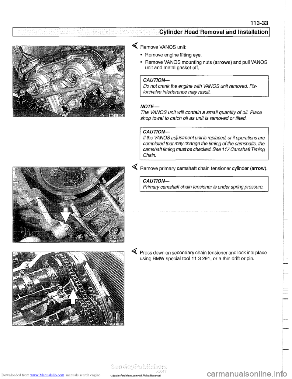
Remove VANOS unit:
Remove engine lifting eye.
- Remove VANOS mounting nuts (arrows) and pull VANOS
unit and metal gasket off.
CAUTION-
Do not crank the engine with VANOS unit removed. Pis-
tonhalve inteiference may result.
NOTE-
The VANOS unit will contain a small quantity of oil. Place
shop towel to catch oil as unit is removed or tilted.
CAUTION-
If the VANOS adjustment unit is replaced, or if operations are
completed that may change the timing of
the camshafts, the
camshaft timing must be checked. See
11 7Camshaft Timing
Chain.
4 Remove primary camshaft chain tensioner cylinder (arrow).
CAUTION-
Primary camshaft chain tensioner is under spring pressure.
Press down on secondary chain tensionerand lock into place
using
BMW special tool 11 3 291, or a thin drifl or pin.