sensor BMW 525i 2000 E39 Workshop Manual
[x] Cancel search | Manufacturer: BMW, Model Year: 2000, Model line: 525i, Model: BMW 525i 2000 E39Pages: 1002
Page 918 of 1002
Downloaded from www.Manualslib.com manuals search engine
51 5-24
l~entral Locking and Anti-Theft
ANTI-THEFT SYSTEM (DWA)
When the anti-then system (DWA) is armed, the doors, hood,
windows, trunk lid or tailgate are monitored against forcible
entry by switches and sensors. The vehicle is protected
against being jacked up or towed away by a tilt sensor.
The control electronics for DWA are integrated in the General
Module (GM). In addition to the control electronics, the sys-
tem includes the following components.
* DWA horn
DWA LED indicator
- Tilt sensor
- Monitoring switches and sensors
The system can be armed or disarmed from the driver's door
lock,
trunklid lock, tailgate lockorthe remote transmitter (FZV
Itey). When armed, the alarm horn
soundsfor30seconds and
the low beam headlights and turn signals flash for
5 minutes.
The electronic immobilizer (EWS) is also activated when
DWA is activated.
The alarm is switched off immediately if key is inserted in door
loclt or FZV key button is used.
DWA LED Status
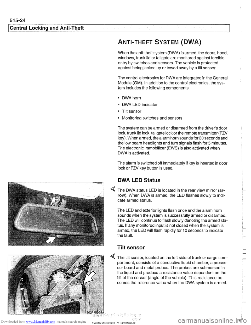
The DWA status LED is located in the rear view mirror (ar-
row). When DWA is armed, the LED flashes slowly to indi-
cate armed status.
The LED and exterior lights flash once and the alarm horn
sounds when the system is successfully armed ordisarmed.
The LED will continue to flash slowly denoting the armed sta-
tus. If any monitored input is not closed when the system is
armed, the LED will flash rapidly for
10 seconds to indicate
the fault.
Tilt sensor
-
4 The tilt sensor, located on the left side of trunlt or cargo com- -
partment, consists of a conductive liquid chamber, a proces-
sor board and metal probes. The probes are submersed in
the liquid and produce a resistance value dependent on the
tilt of the sensor (angle of the vehicle). This resistance be-
comes the reference value when the DWA system is armed.
.-
Page 919 of 1002
Downloaded from www.Manualslib.com manuals search engine
51 5-25
Central Lockina and ~nti-~heftl
1
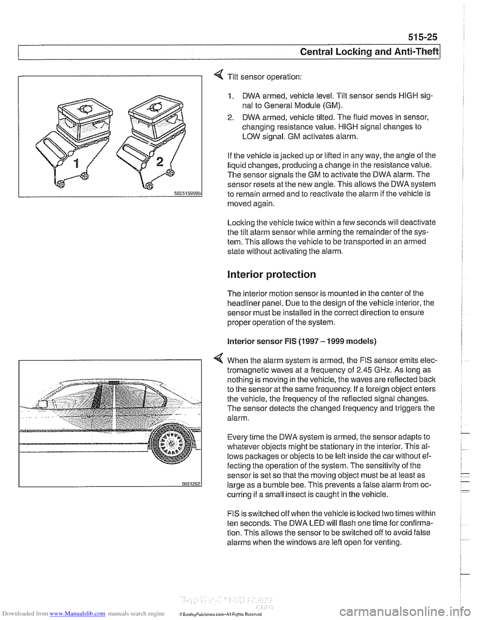
Tilt sensor operation:
1. DWA armed, vehicle level. Tilt sensor sends HlGH sig-
nal to General Module (GM).
2. DWA armed, vehicle tilted. The fluid moves in sensor,
changing resistance value.
HlGH signal changes to
LOW signal. GM activates alarm.
If the vehicle is jacked up or lifted in any way, the angle of the
liquid changes, producing a change in the resistance value.
The sensor signals the GM to activate the DWA alarm. The
sensor resets at the new angle.
This allows the DWA system
to remain armed and to reactivate the alarm if tlie vehicle is
moved again
Locking the vehicle twice within a few seconds will deactivate
the tilt alarm sensor while arming tlie remainder of the sys-
tem. This allows the vehicle to be transported in an armed
state without activating tlie alarm.
Interior protection
The interior motion sensor is mounted in the center of the
headliner panel. Due to the design of the vehicle interior, the
sensor must be installed in the correct direction to ensure
proper operation of the system.
lnterior sensor FIS (1997 - 1999 models)
4 When the alarm system is armed, the FIS sensor emits elec-
tromagnetic waves at
a frequency of 2.45 GHz. As long as
nothing is moving in the vehicle, the waves are reflected
baclc
to the sensor at the same frequency. If a foreign object enters
the vehicle, the frequency of the reflected signal changes.
The sensor detects the changed frequency and triggers the
alarm.
Every time the DWA system is armed, the sensor adapts to
whatever objects might be stationary in the interior. This al-
lows pacltages or objects to be left inside tlie car without ef-
fecting the operation of the system. The sensitivity of the
sensor is set so that the moving object must be at least as
large as a bumble bee. This prevents a false alarm from oc-
curring if a small insect is caught in the vehicle.
FIS is switched off when the vehicle is locked two times within
ten seconds. The DWA LED will flash one time for confirma-
tion. This allows the sensor to be switched off to avoid false
alarms when the windows are left open for venting.
Page 920 of 1002
Downloaded from www.Manualslib.com manuals search engine
51 5-26
Central Locking and Anti-Theft
Interior sensor UIS (2000 and later models)
The
UIS system uses ultrasonic sound waves instead of elec-
tromagnetic waves. Ultrasonic sound waves are less suscep-
tible to magnetic interference.
Every time the DWA system is armed, the sensor adapts to
whatever objects might be stationary in the interior. The sen-
sor emits ultrasonic waves in a programmed timed cycle. It re-
ceives echoes of the emitted waves. The
UIS amplifies the
received sound wave signals and compares them to the ech-
oes of the transmitted waves. The
UIS also checits the incom-
ing echoes for background hiss (wind noise through a
partially open window) and adapts for this.
If the echoes are consistently similar, no movement is de-
tected.
If the echoes are altered, (inconsistent), the UIS deter-
mines motion in the interior compartment.
If motion is detected, the
UIS changes to a constant cycle
and the echo is compared again.
If the inconsistency is still present the
UIS sends the acti-
vate siren signal to the GM.
Glass breakage sensors
The doorwindows are monitored by inductive sensors mount-
ed on the inside of the door behind the trim panel. A closed
window is recognized by a magnetic plate
on the glass lining
up with the sensor. If the glass is broken, the plate falls away
and the signal from the sensor changes. This causes the GM
to activate the alarm.
Emergency disarming
- An emergency procedure is provided to cancel the DWA in
the event that a fault occurs within the system. The procedure
is as follows:
Driver's door mechanically
unloclted and open within 30
seconds. This will cause triggering of alarm.
All doors closed.
Ignition switch turned to
KL R (ACCESSORY). LED indica-
tor will come on.
- After 10 minutes, alarm is disarmed
Page 949 of 1002
Downloaded from www.Manualslib.com manuals search engine
721 Airbag System (SRS)
........................... General ............................ 721-2 Airbags 721-8
..... E39Airbags ......................... 721-3 Driver airbag. removing and installing 721-8
Two-stage airbag (MRS 111) ............ .72 1.4 Passenger airbag. removing and installing . 721-9
Airbag indicator light .................. .72 1.4 Door mounted side-impact airbag.
............... Warninas .......................... .72 1.5 removina and installina 721-10 .
..... Head protection airbag components 721
-1 1 Airbag Electronics ................. '721-6 Head protection airbag (HpS) .......... 721-12 MRS ............................... 721-6
MRS
airbag system diagram ........... .72 1.6
MRS control module. replacing ......... .72 1.7
Side-impact crash sensor.
removing and installing
................ .72 1.7
Page 950 of 1002
Downloaded from www.Manualslib.com manuals search engine
721 -2
l~irba~ System (SRS)
This repair group covers airbag components and replace-
ment.
Airbag system repairand fault diagnosis is not covered.
Diagnostics, component testing, and
airbag system repair
should be carried out by trained BMW service technicians.
Individual
airbag system components can only be tested elec-
tronically when installed in the car. BMW service testers
DIS
or MoDiC or equivalent must be used for diagnostic work.
WARNING-
Special test equipment is required to retrieve airbag fault
codes, diagnose system faults, and
reseffturn off the air-
bag indicator light. The indicator light will remain on until
any problem has been corrected and the fault memory has
been cleared.
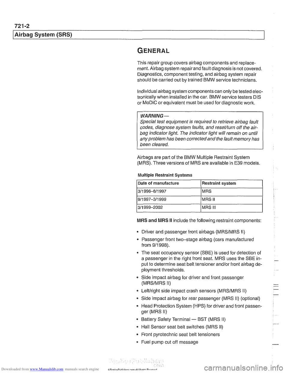
Airbags are part of the BMW Multiple Restraint System
(MRS). Three versions of MRS are available in E39 models.
Multiple Restraint Systems
MRS and MRS II include the following restraint components:
311 996-811 997
911
997-311 999
311 999-2002
Driver and passenger front
airbags (MRSIMRS II)
MRS
MRS
II
MRS Ill
Passenger front two-stage airbag (cars manufactured
from
911998).
The seat occupancy sensor (SBE) is used for detection of
a passenger in the right front seat. MRS uses the SBE in-
put to determine seat belt tensioner
and/or front airbag de-
ployment thresholds.
Side impact
airbag for driver and front passenger
(MRSIMRS II)
Leftlright side impact crash sensors (MRSIMRS 11)
Side impact airbag for rear passenger (MRS II) (optional)
Head Protection System (HPS) for driver and front passen-
ger (MRS
II)
Battery Safety Terminal - BST (MRS II)
Hall Sensor seat belt switches (MRS II)
Front pyrotechnic seat belt tensioners
Fuel pump cut off message
Page 951 of 1002
Downloaded from www.Manualslib.com manuals search engine
721 -3
Airbag System (SRS)
MRS Ill adds the following features:
MRS
Ill employs "smart" technology. Smart technology re-
fers to the control module's programming for the deploy-
ment of the airbags, in stages depending on the severity of
the impact.
Two-stage a~rbag for ooln drver and passenger Alloivs for
a softer
c~snioning elfecl when the airbags are lr ggered at
lighter impact,
MRS
Ill satellite sensors use 2 wire connectors
Rear side
airbags arrive de-activated from the factory and
can only be activated upon written request from the cus-
tomer.
Rear seat head protection is available when ordered with
optional rear seat side airbags.
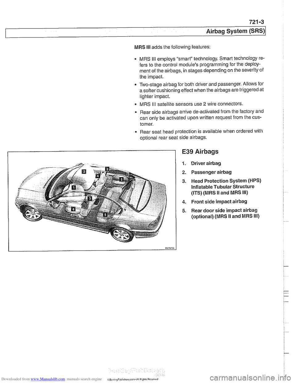
E39 Airbags
Driver airbag
Passenger airbag
Head Protection System (HPS)
Inflatable Tubular Structure
(ITS) (MRS
II and MRS Ill)
Front side impact airbag
Rear door side impact airbag
(optional) (MRS I1 and MRS Ill)
Page 952 of 1002
Downloaded from www.Manualslib.com manuals search engine
I Airbag System (SRS)
Two-stage airbag (MRS Ill)
Beginning with 2000 model year (911 999 production) the front
airbags were changed to a two-stage style airbag. This en-
sures that the force of
airbag inflation is not greater than nec-
essary to provide
protection. The airbags are designed to
Drovide "soit" de~lovment if the acceleration sensor detects a
iow-speed impact, and "hard deployment in higher speed im-
pacts.
NOTE-
A two-stage passenger airbag was used on cars built be-
tween
9/1998 and 3/1999. This pre-smart technology airbag
used two ignition stages. Stage one is designed to ignite first
during an impact. Stage two ignites after a timed period, as
programmed in the MRS
I1 control module.
Airbag indicator light
The MRS control module detects and stores system status
The
airbag indicator light in the instrument cluster displays
the status of the
airbag system when the ignition key is in "ac-
cessory" or
ON positions.
System normal: lndicator light comes on briefly, then goes
out.
- System malfunction: lndicator light fails to come on.
System malfunction: lndicator light comes on briefly, goes
out and lights up again.
The
airbag indicator light also comes on if the seat belt pyro-
technic tensioners have been triggered.
Page 954 of 1002
Downloaded from www.Manualslib.com manuals search engine
721-6
I Airbag System (SRS)
MRS
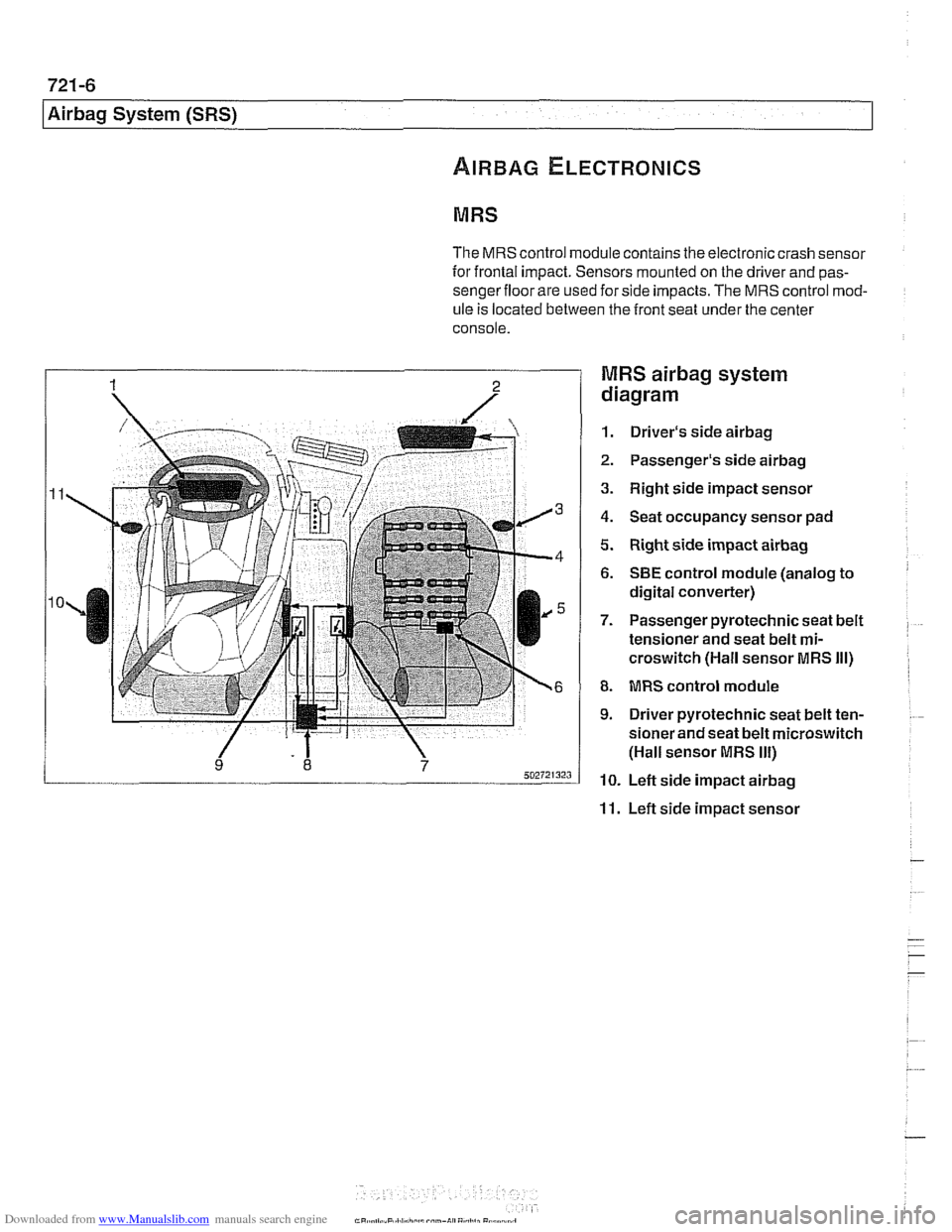
The MRS control module contains the electronic crash sensor
for frontal impact. Sensors mounted on the driver and
pas-
sengerfloor are used for side impacts. The MRS control mod-
ule
is located between the front seat under the center
console.
MRS airbag system
diagram
1. Driver's side airbag
2. Passenger's side airbag
3. Right side impact sensor
4. Seat occupancy sensor pad
5. Right side impact airbag
6. SBE control module (analog to
digital converter)
7. Passenger pyrotechnic seat belt
tensioner and seat belt
mi-
croswitch (Hall sensor MRS Ill)
8. MRS control module
9. Driver pyrotechnic seat belt ten-
sioner and seat belt microswitch
(Hall sensor MRS
Ill)
10. Left side impact airbag
11. Left side impact sensor
Page 955 of 1002
Downloaded from www.Manualslib.com manuals search engine
Airbag System (SRS)~
MRS control module, replacing
- Disconnect negative (-) cable from battery and cover nega-
tive terminal with insulating material.
CAUTIOI\C
Prior to disconnecting the battery, read the battery discon-
nection cautionsgiven in001 General Warnings and
Cau-
tions.
- Remove center console between front seats. See 513 lnteri-
or Trim.
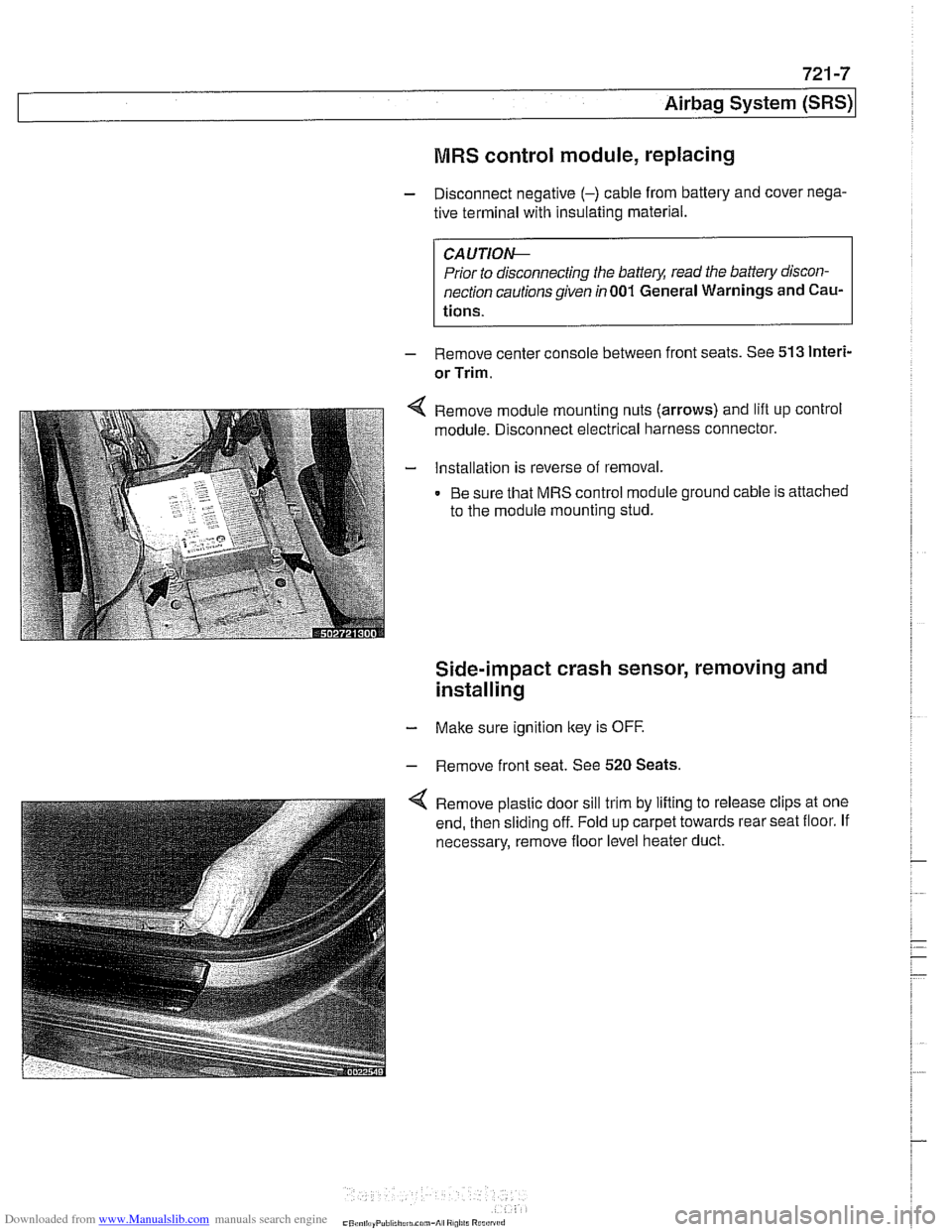
Remove module mounting nuts (arrows) and lift up control
module. Disconnect electrical harness connector.
Installation is reverse of removal.
Be sure that MRS control module ground cable is attached
to the module mounting stud.
Side-impact crash sensor, removing and
installing
- Make sure ignition key is OFF.
- Remove front seat. See 520 Seats.
Remove plastic door sill trim by lifting to release clips at one
end, then sliding off. Fold up carpet towards rear seat floor. If
necessary, remove floor level heater duct.
Page 956 of 1002
Downloaded from www.Manualslib.com manuals search engine
721 -8
(Airbag System (SRS)
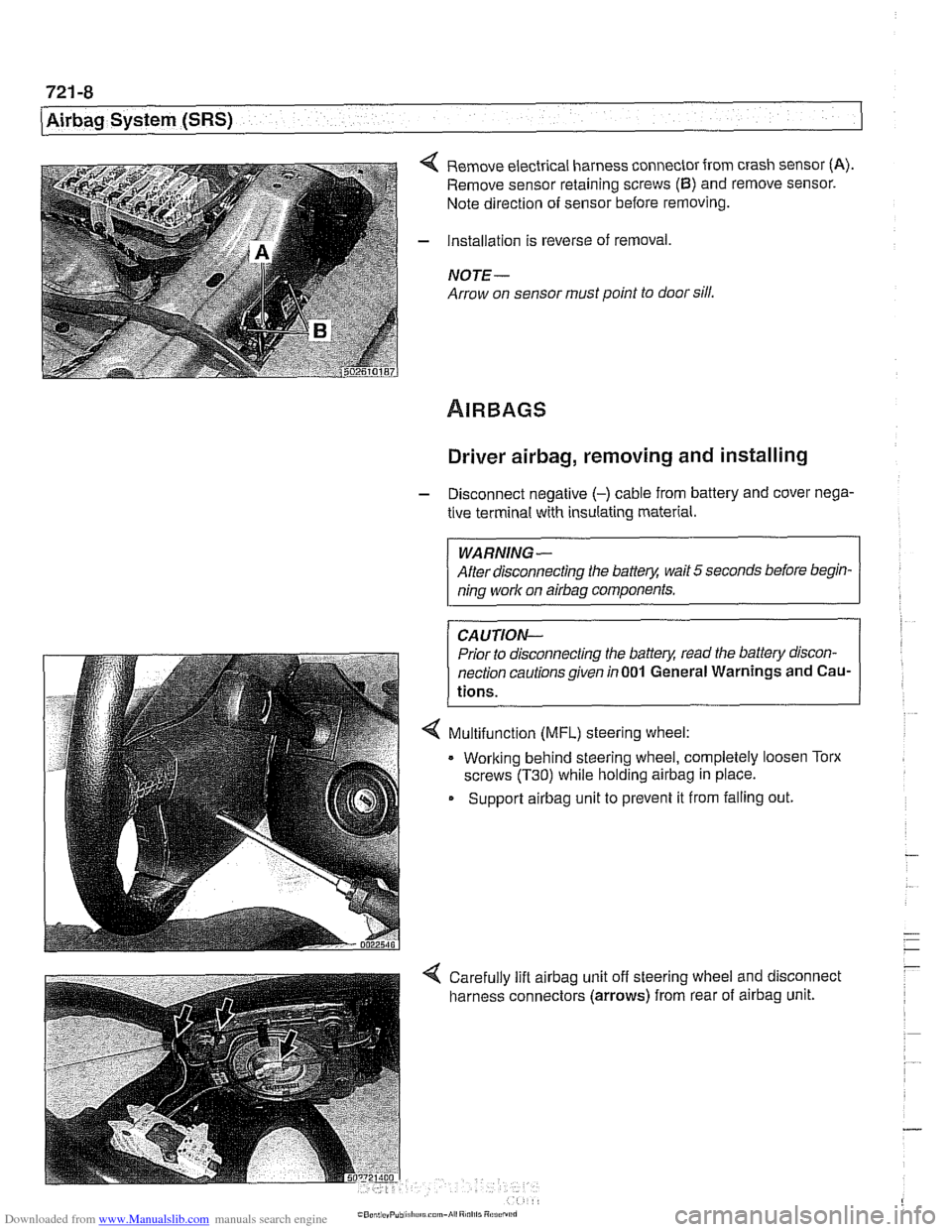
4 Remove electrical harness connector from crash sensor (A).
Remove sensor retaining screws (6) and remove sensor.
Note direction of sensor before removing.
- Installation is reverse of removal,
NOTE -
Arrow on sensor must point to door sill.
Driver airbag, removing and installing
- Disconnect negative (-) cable from battery and cover nega-
tive terminal with insulating material.
WARNING-
After disconnecting the batter)! wait 5 seconds before begin-
ning work on
airbag components.
CAUTION-
Prior to disconnecting the batter)! read the battery discon-
nection cautionsgiven
in001 General Warnings and Cau-
tions.
4 Multifunction (MFL) steering wheel:
. Working behind steering wheel, completely loosen Torx
screws
(T30) while holding airbag in place.
Support
airbag unit to prevent it from falling out.