sensor BMW 525i 2000 E39 Workshop Manual
[x] Cancel search | Manufacturer: BMW, Model Year: 2000, Model line: 525i, Model: BMW 525i 2000 E39Pages: 1002
Page 733 of 1002
Downloaded from www.Manualslib.com manuals search engine
Rear suspension/
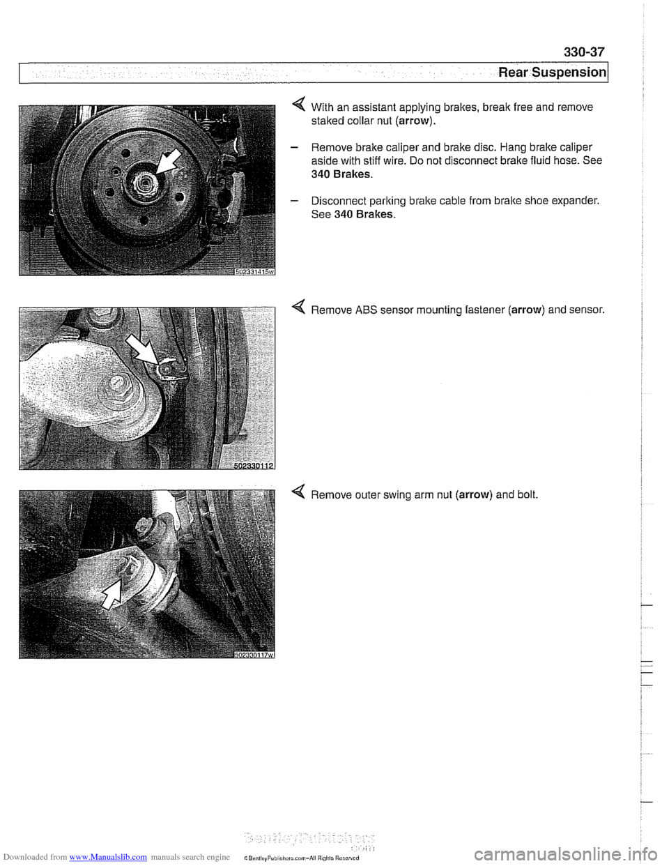
4 With an assistant applying brakes, break free and remove
staked collar nut (arrow).
- Remove brake caliper and brake disc. Hang bralte caliper
aside with stiff wire. Do not disconnect brake fluid hose. See
340 Brakes.
- Disconnect parking brake cable from brake shoe expander.
See 340 Brakes.
Remove ABS sensor mounting fastener
(arrow) and sensor.
Remove outer swing arm nut (arrow) and bolt.
Page 735 of 1002
Downloaded from www.Manualslib.com manuals search engine
330-39
I Rear suspension1
- Remainder of installation is reverse of removal, noting the fol-
lowing.
Models with coil springs: Fit spring correctly in lower spring
seat.
* Models with air suspension: Fit eccentric lug at bottom of
air spring in recess of wheel carrier spring seat.
Always use new self-locking nuts.
- Make sure all threaded bolts, nuts and mating surfaces are
clean.
a Tighten fasteners to final torque only after vehicle has
been lowered and suspension has settled.
Stake axle collar nut afler tightening.
Tightening torques
ABS pulse sensor to wheel bearing 8 Nm (6
ft-lb)
carrier
Air spring to wheel bearing carrier 20 Nm (15 ft-lb)
Brake rotor to hub 16 Nm (12
it-lb)
Rear axle shaft to hub (M27) 300 Nm (221 ft-lb)
Rear brake pad carrier (caliper) to wheel 65 Nm (48 ft-lb)
bearing carrier
Road wheel to hub
120ilONm
(89 k7 ft-lb)
Swing arm to wheel bearing carrier 256 Nm (189 it-lb)
Upperfrontcontrol arm (traction strut) to 65 Nm (48 ft-lb)
wheel carrier
Upper rear control arm to wheel carrier 142 Nm (105 ft-lb)
Rear wheel bearing, replacing
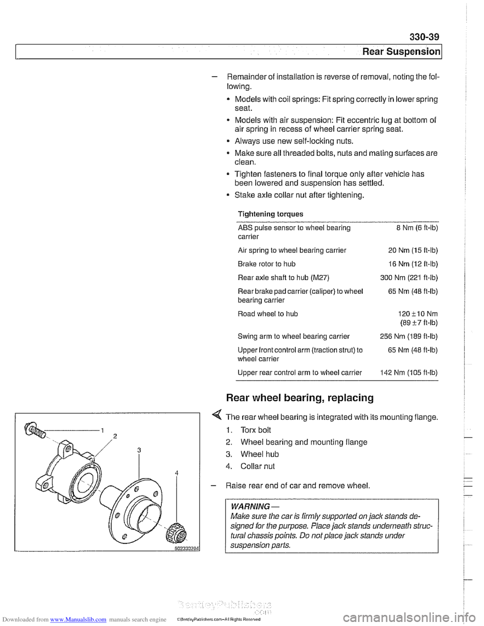
< The rear wheel bearing is integrated with its mounting flange.
1. Torx bolt
2. Wheel bearing and mounting flange
3. Wheel hub
4. Collar nut
- Raise rear end of car and remove wheel.
WARNING -
Make sure the car is firmly supported on jaclc stands de-
signed for the purpose. Place jack stands underneath struc-
tural chassis points. Do not place jack stands under
suspension parts.
Page 736 of 1002
Downloaded from www.Manualslib.com manuals search engine
330-40
Rear Suspension
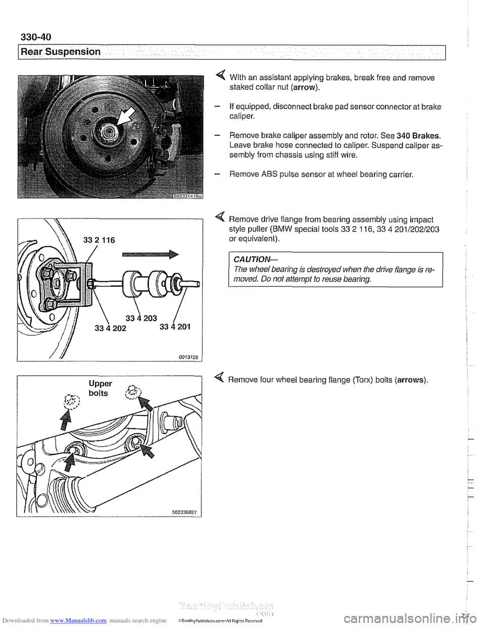
4 With an assistant applying brakes, break free and remove
staked collar nut (arrow).
- If equipped, disconnect brake pad sensor connector at brake
caliper.
- Remove brake caliper assembly and rotor. See 340 Brakes.
Leave brake hose connected to caliper. Suspend caliper as-
sembly from chassis using stiff wire.
- Remove ABS pulse sensor at wheel bearing carrier.
Remove drive flange from bearing assembly using impact
style puller
(BMW special tools 33 2 116, 33 4 201/202/203
or equivalent).
CAUTION-
The wheel bearing is destroyed when the drive flange is re-
moved. Do not attempt to reuse bearing.
4 Remove four wheel bearing flange (Torx) bolts (arrows)
Page 738 of 1002
Downloaded from www.Manualslib.com manuals search engine
330-42
/Rear Suspension
- Install ABS sensor and road wheel.
- Lower car to ground. With an assistant applying brakes, use
new axle collar nut to tighten to final torque. Stake nut.
- Remainder of installation is reverse of removal
Tightening torques ABS pulse sensor to wheel bearing carrier
8 Nm (6 ft-lb)
Brake disc to hub
16 Nm
Rear
brake pad carrier (caliper) to wheel
65 Nm (48 ft-lb)
bearing carrier
Rear axle shaft to hub
(M27) 300 Nrn (221 ft-lb)
Road wheel to hub 120F10 Nm
(89 ?7 ft-lb)
The rearstabilizer bar is mounted to the rear
subframe and at-
tached via stabilizer bar
linlts to the lower swing arms.
Stabilizer bar, removing and installing
- Raise rear end of car.
WARNING -
Make sure the car is firmly supported on jack stands de-
signed for the purpose. Place jack stands underneath struc-
tural chassis points.
Do not place jack stands under
suspension parts.
- Paint mark stabilizer bar on left side for ease of assembly.
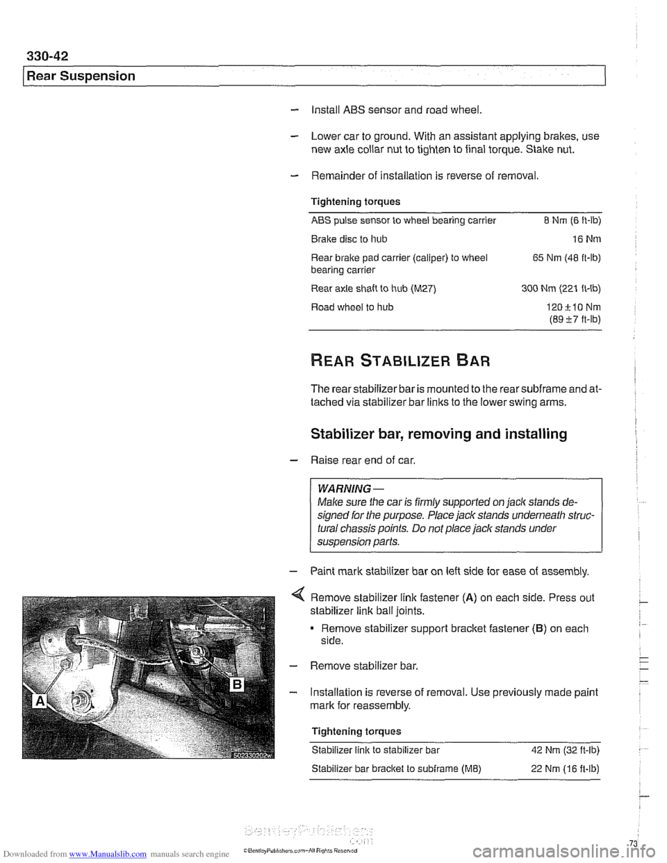
Remove stabilizer link fastener
(A) on each side. Press out
stabilizer link ball joints.
Remove stabilizer support bracket fastener
(B) on each
side.
Remove stabilizer bar.
Installation is reverse of removal. Use previously made paint
mark for reassembly.
Tightening torques Stabilizer link to stabilizer bar
42 Nm (32 ft-lb)
Stabilizer bar bracket to sublrame (ME) 22 Nm (1 6 fi-lb)
Page 740 of 1002
Downloaded from www.Manualslib.com manuals search engine
---
Rear Suspension
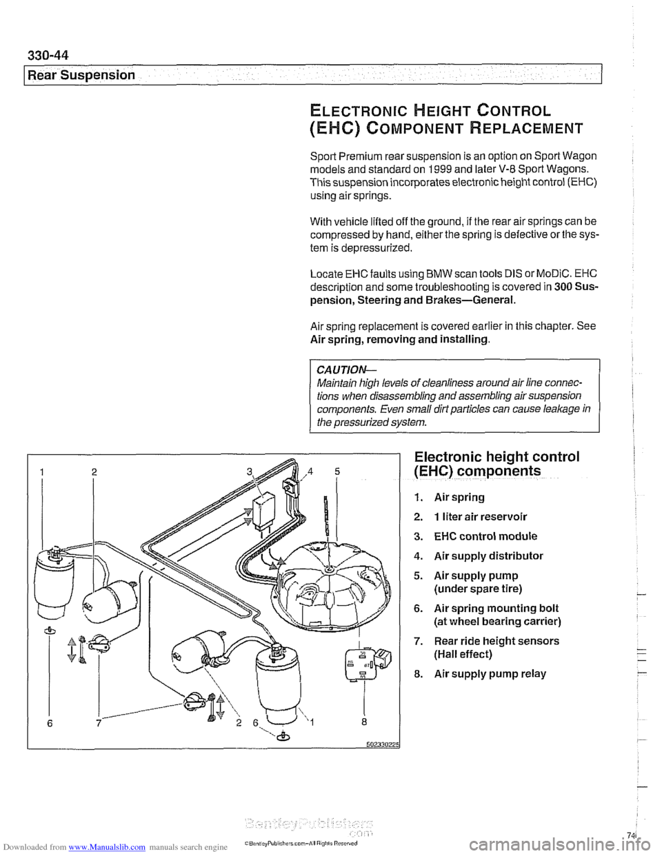
ELECTRONIC HEIGHT CONTROL
(EHC) COMPONENT REPLACEMENT
Sport Premium rear suspension is an option on Sport Wagon
models and standard on
1999 and later V-8 Sport Wagons.
This suspension incorporates electronic height control
(EHC)
using air springs.
With vehicle lifted off the ground,
if the rear air springs can be
compressed by hand, either the spring is defective or the sys-
tem is depressurized.
Locate
EHC faults using BMW scan tools DIS or MoDiC. EHC
description and some troubleshooting is covered in 300 Sus-
pension, Steering and Brakes-General.
Air spring replacement is covered earlier in this chapter. See
Air spring, removing and installing.
CAUTION-
Maintain high levels of cleanliness around air line connec-
tions when disassembling and assembling air suspension
components. Even
small dirt particles can cause leakage in
the pressurized system.
Electronic height control
(EHC) components
1. Air spring
2. 1 liter air reservoir
3. EHC control module
4. Air supply distributor
5. Airsupply pump
(under spare tire)
6. Air spring mounting bolt
(at wheel bearing carrier)
7. Rear ride height sensors
(Hall effect)
8. Air supply pump relay
Page 743 of 1002
Downloaded from www.Manualslib.com manuals search engine
330-47
Rear suspension/
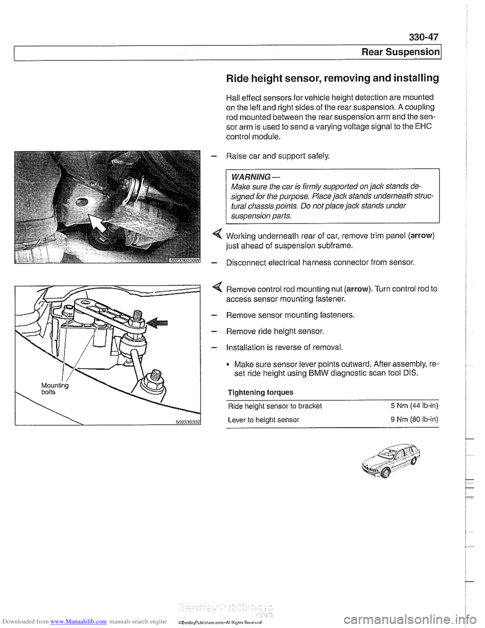
Ride height sensor, removing and installing
Hall effect sensors for vehicle height detection are mounted
on the
left and right sides of the rear suspension. A coupling
rod mounted between the rear suspension arm and the sen-
sor arm is used to send a varying voltage signal to the
EHC
control module.
Raise car and support safely.
WARNING-
Male sure the car is firmly supported on jaclc stands de-
signed
for the purpose. Place jaclc stands underneath struc-
tural chassis points. Do not place jaclc stands under
sus~ension Darts.
Working underneath rear of car, remove trim panel (arrow)
just ahead of suspension subframe.
Disconnect electrical harness connector from sensor.
4 Remove control rod mounting nut (arrow).Turn control rod to
access sensor mounting fastener.
- Remove sensor mounting fasteners.
- Remove ride height sensor.
- Installation is reverse of removal.
Make sure sensor lever points outward. After assembly, re-
set ride height using BMW diagnostic scan tool DIS.
Tightening torques
Ride
height sensor to bracket 5 Nrn (44 lb-in)
Lever to height sensor
9 Nrn (80 ib-in)
Page 763 of 1002
Downloaded from www.Manualslib.com manuals search engine
General ........................... .34 0.2
Special Tools
....................... .34 0.2
E39 brake system
.................... .34 0.4
Electronic braking and stability control
.... .34 0.4
Troubleshooting
..................... .34 0.5
Warnings and cautions
................ .34 0.7
Bleeding Brakes ................... .34 0.8
Brakes, bleeding
..................... .34 0.9
Brake Pads, Calipers and Rotors ... .34 0.1 1
Braking system components .......... .34 0.11
Brake pads,
checking and replacing ..... .34 0.12
Brake rotors, removing and installing
.... .34 0.15
Master Cylinder .................. .34 0.16
Master cylinder, removing and installing
. .34 0.17
Brake Booster .................... .349 0.1
Brake booster check valve
............ .34 0.19
Brake booster, removing and installing
.. .34 0.20
Parking Brake .................... .34 0.22
Parking brake components
............ .34 0.22
Parking
brake, adjusting .............. .34 0.22
Parking bralte shoes, removing
and installing
....................... .34 0.23
Parking
brake cable, replacing ......... .34 0.24
ABS Component Replacement ..... 340-26
Wheel speed sensor. replacing
......... 340-26
ABS impulse wheel
.................. 340-27
DSC lateral acceleration or
rotational rate (yaw) sensor. replacing
... 340-27
DSC steering angle sensor.
removing and installing
............... 340-28
DSC precharge pump.
removing and installing (1998 models)
... 340-29
DSC pressure sensor
(1 999 - 2002 models) ................ 340-30
ABS /traction electronic control
module
(1 997 -1 998 models) .......... 340-31
ABS
/ DSC control module
(1 999
- 2002 models) ................ 340-31
ABS
/ traction control hydraulic unit.
removing and installing
............... 340-31
Page 765 of 1002
Downloaded from www.Manualslib.com manuals search engine
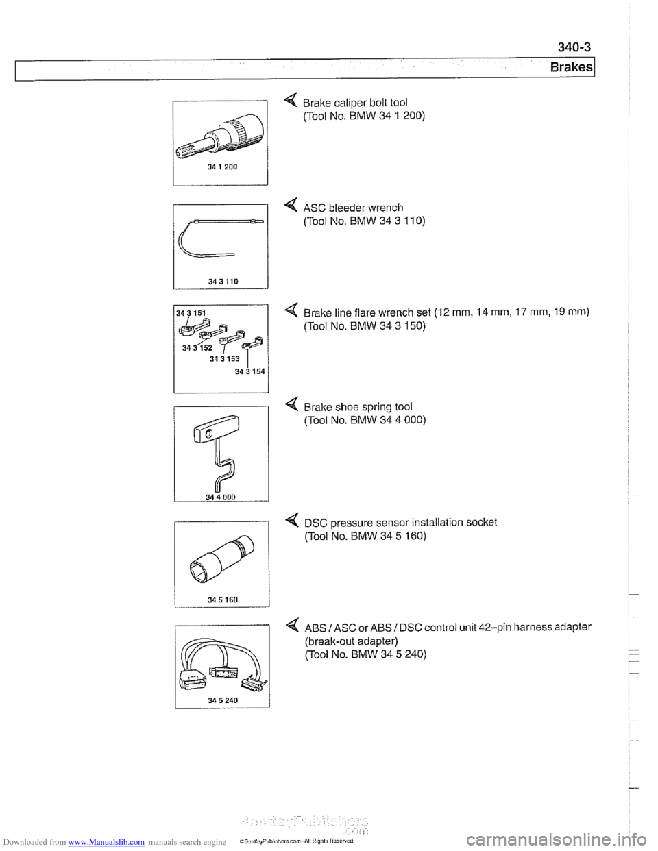
, Brake caliper bolt tool
4 ASC bleeder wrench
(Tool No. BMW 34
3 110)
4 Brake line flare wrench set (12 mm, 14 mm, 17 mm, 19 rnm)
(Tool No. BMW 34 3 150)
34 3 152
34 3 153
34 3 154
4 DSC Dressure sensor installation socltet
4 ABS IASC or ABSI DSC control unit 42-pin harness adapter
(break-out adapter)
(Tool No. BMW 34 5 240)
0
(Tool NO. BMW 34 5 160)
Page 766 of 1002
Downloaded from www.Manualslib.com manuals search engine
E39 brake system
BMW E39 models are equipped with vacuum power-assisted
four-wheel disc brakes with an integral
Antilock Brake System
(ABS). Single-piston calipers act on vented front and rear ro-
tors. A brake pad wear sensor for each axle indicates when
brake pads need replacement. The dual drum-type parking
brake system is integrated with the rear brake rotors.
Electronic braking and stability control
E39 models were introduced with Automatic Stability Control,
a computer controlled traction control system that uses the
AB5 system in conjunction with engine management controls
to control wheel spin during take-off and maintain vehicle sta-
bility while braking.
Added in the
1998 model year was Dynamic Stability Control
(DSC). This system implements wheel speed modulation
throughout all stages of driving. For example, DSC is able to
reduce understeer by applying differing amounts of braking
force to each wheel, or it can override the engine manage-
ment system during hard cornering.
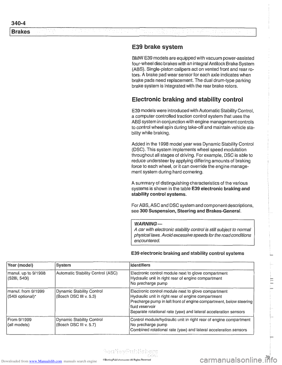
A summary of distinguishing characteristics of the various
systems is shown in the table
E39 electronic braking and
stability control systems.
For ABS, ASC and DSC system and component descriptions,
see
300 Suspension, Steering and Brakes-General.
WARNING-
A car with electronic stability control is still subject to normal
physical laws. Avoid excessive speeds for the road conditions
encountered.
E39 electronic braking and stability control systems
Year (model)
manuf. up to 911998
(528i, 540i)
manuf. from 911999
(540i optional)*
From
911 999
(ail models) System
Automatic Stability Control (ASC) Identifiers
Electronic control module next to glove compartment
Hydraulic unit in right rear of engine compartment
No precharge pump
Dynamic Stability Control
(Bosch DSC
Ill v. 5.3)
Dynamic
Stabil~ty Control
(Bosch DSC
Ill v. 5.7) Electronic
control module next to glove compartment
Hydraulic unit in right rear of engine compartment
Precharge pump in left front of engine compartment, below steering
fluid reservoir
Separate rotational rate (yaw) and lateral acceleration sensors
Control
modulelhydraulic unit in right rear of engine compartment
No precharge pump
Combined rotational rate (yaw) and lateral acceleration sensors
Page 773 of 1002
Downloaded from www.Manualslib.com manuals search engine
Brakes
BRAKE PADS, CALIPERS AND ROTORS
Brake pads,
calipers, and rotors
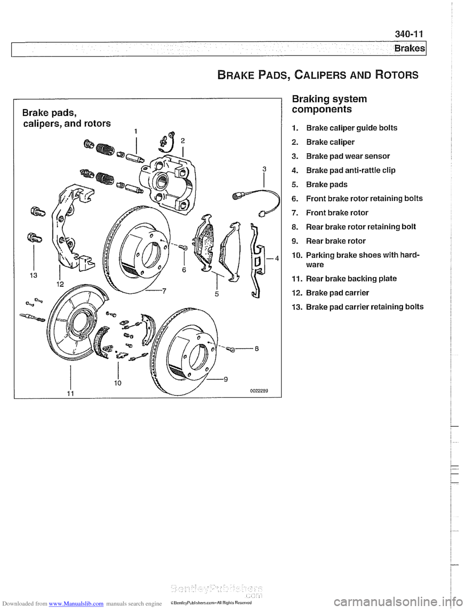
Braking system
components
1. Brake caliper guide bolts
2. Brake caliper
3. Brake pad wear sensor
4. Brake pad anti-rattle clip
5. Brake pads
6. Front brake rotor retaining bolts
7. Front brake rotor
8. Rear brake rotor retaining bolt
9. Rear brake rotor
10. Parking brake shoes with hard-
ware
11. Rear brake backing plate
12. Brake pad carrier
13. Brake pad carrier retaining bolts