brake sensor BMW 525i 2000 E39 Workshop Manual
[x] Cancel search | Manufacturer: BMW, Model Year: 2000, Model line: 525i, Model: BMW 525i 2000 E39Pages: 1002
Page 33 of 1002
Downloaded from www.Manualslib.com manuals search engine
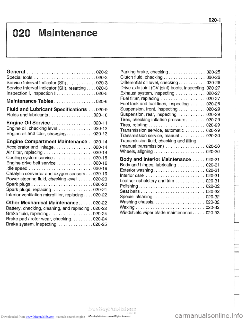
020 Maintenance
General ........................... .02 0.2
Special tools ........................ .02 0.2
Service Interval Indicator (Sll) ........... .02 0.3
Service Interval Indicator (Sll), resetting ... .02 0.3
Inspection I, Inspection 11 ............... .02 0.5
Maintenance Tables ................ .02 0.6
Fluid and Lubricant Specifications .. .02 0.9
Fluids and lubricants ................. .02 0.10
Engine Oil Service ................ .02 0.1 I
Engine oil. checking level ............. .02 0.12
Engine oil and filter. changing .......... .02 0-13
Engine Compartment Maintenance . .02 0.14
Accelerator and linkage ............... .02 0.14
Air filter. replacing ................... .02 0.1 4
Cooling system service ............... .02 0.15
Engine drive belt service .............. .02 0.16
Idlespeed .......................... 020-19
Catalytic converter and oxygen sensors .. .02 0.19
Power steering fluid, checking level ..... .02 0.20
Spark plugs ........................ .02 0.20
Spark plugs, replacing ................ .02 0.21
Interior ventilation microfilter, replacing ... .02 0.22
Other Mechanical Maintenance ..... .02 0.22
Battery, checking. cleaning. and replacing .02 0-22
Brake fluid. replacing ................. .02 0-24
Brake pad 1 rotor wear. checking ........ .02 0.24
Brake system, inspecting ............. .02 0.25
Parking brake. checking ............... 020-25
Clutch fluid. checking ................. 020-26
Differential oil level. checking ........... 020-26
Drive axle joint (CV joint) boots. inspecting 020-27
Exhaust system. inspecting ............ 020-27
Fuel filter. replacing .................. 020-27
Fuel tank and fuel lines. inspecting ...... 020-28
Suspension. front. inspecting ........... 020-29
Suspension. rear. inspecting ........... 020-29
Tires. checking inflation pressure ........ 020-29
Tires. rotating ....................... 020-29
Transmission service. automatic ........ 020-29
Transmission service. manual .......... 020-30
Transmission fluid. checking and filling
(manual transmission)
................ 020-30
Wheels. aligning ..................... 020-30
Body and Interior Maintenance ..... 020-31
Body and hinges. lubricating ........... 020-31
Exterior washing ..................... 020-31
Interior care ........................ 020-31
Leather upholstery and trim ............ 020-31
Polishing ........................... 020-32
Seat belts .......................... 020-32
Special cleaning ..................... 020-32
Washing chassis ..................... 020-32
Waxing ............................ 020-32
Windshield wiper blade maintenance ..... 020-33
Page 41 of 1002
Downloaded from www.Manualslib.com manuals search engine
--- -
Maintenance
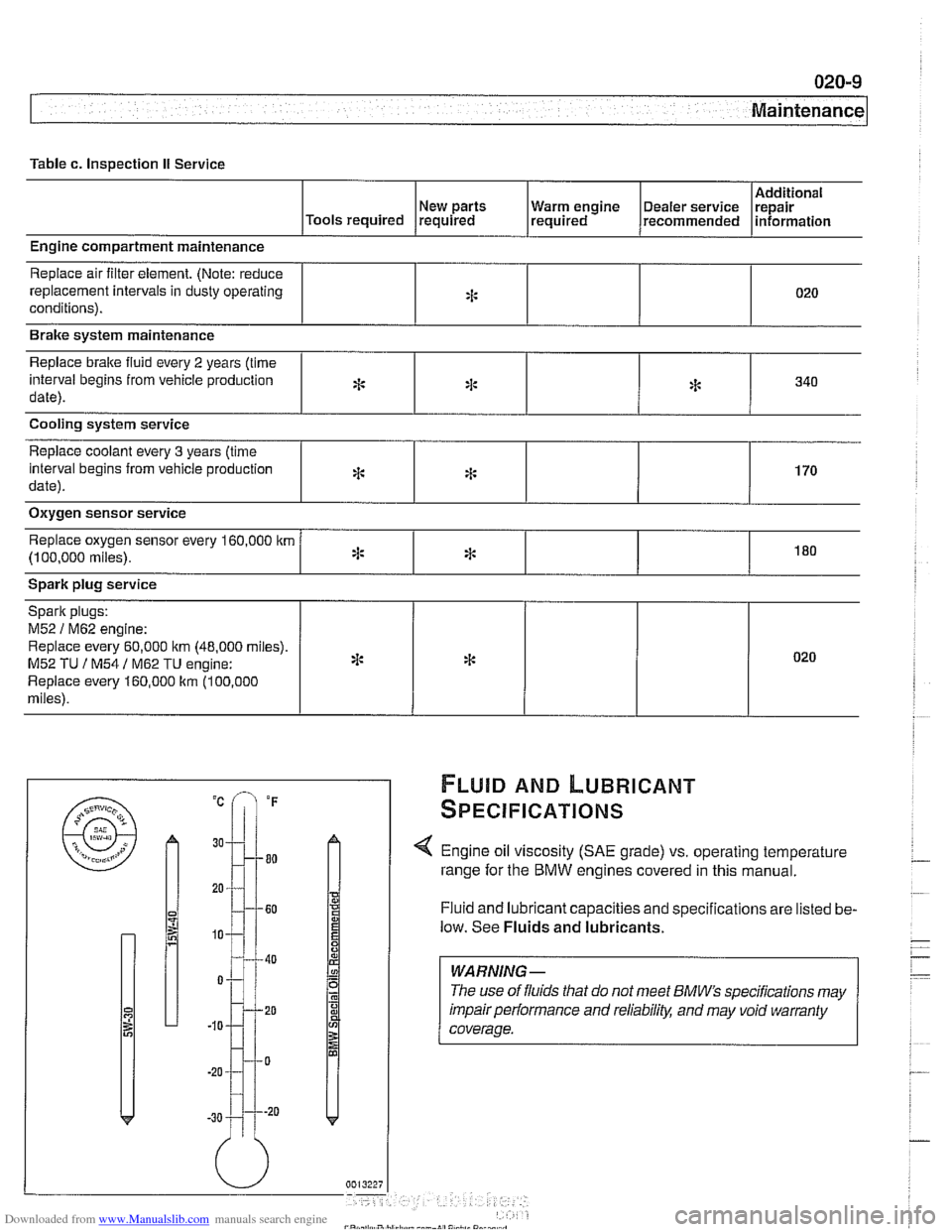
Table c. Inspection II Service
Additional
New parts Warm engine Dealer service repair
Tools required required required recommended information
Engine compartment maintenance
Replace air filter element. (Note: reduce
replacement intervals in dusty operating
conditions).
Replace brake
fluid every 2 years (time
interval begins from vehicle production
date).
Cooling system service
Spark plug service
Brake
system maintenance
:j:
*
Replace coolant every 3 years (time
interval begins from vehicle production
date).
Replace oxygen sensor every 160,000
itm
(1 00,000 miles).
020
FLUID AND LUBRICANT
SPECIFICATIONS
:I:
Oxygen sensor service
*
x:
Spark plugs:
M52
1 M62 engine:
Replace every 60,000 itm (48.000 miles).
M52
TU I M54 1 M62 TU engine:
Replace every 160,000
ltm (100.000
miles).
< Engine oil viscosity (SAE grade) vs. operating temperature
range for the BMW engines covered in this manual.
Fluid and lubricant capacities and specifications are listed be-
low. See
Fluids and lubricants.
:I:
*
*
*
WARNING -
The use of fluids that do not meet BMW" specifications may
impair performance and
reliabilitl: and may void warranty
coverage.
340
170
180
* 020
Page 90 of 1002
Downloaded from www.Manualslib.com manuals search engine
I Engine Removal and Installation
WARNING -
Use extreme caution when draining and disposing of engine
coolant. Coolant is poisonous andlethal to humans andpets.
Pets are attracted to coolant because of its sweet smell and
taste. Seek medical attention immediately if coolant is ingest-
---
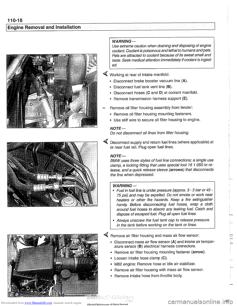
Working at rear of intake manifold:
Disconnect brake booster vacuum line (A).
Disconnect fuel tank vent line
(6).
Disconnect hoses (C and D) at coolant manifold
- Remove transmission harness support (E).
- Remove oil filter housing assembly from fender:
- Remove oil filter housing mounting fasteners.
Use stiff wire to secure oil filter housing to engine.
NOTE-
Do not disconnect oil lines from filter housing.
4 Disconnect supply and return fuel lines (where applicable) at
or near fuel rail. Plug open fuel lines.
NOTE-
BMW uses three styles of fuel line connections; a slngle use
clamp, a locking fitting that uses special tool
16 7 050 to re-
lease, and a
quiclc release sleeve (arrows) that disconnects
the line when depressed.
WARNING-
Fuel In fuel line is under pressure (approx. 3 - 5 bar or45 -
75 psi) and may be expelled. Do not smoke or worlc near
heaters or other fire hazards. Keep a fire extinguisher
handy. Before disconnecting fuel hoses, wrap a cloth
around fuel hoses to absorb any lealcing fuel. Catch and
dispose of escaped fuel. Plug all open fuel lines.
. Always unscrew the fuel tank cap to release pressure
in the tank before worlcing on the tank or lines.
< Remove air filter housing and mass air flow sensor:
Disconnect mass air flow sensor (A) and
intalte air temper-
ature sensor
(6) electrical harness connectors.
. Remove air filter housing mounting fastener (arrow).
Loosen intake hose clamp (C).
M62 engine: Remove hose at idle air stabilizer.
Remove air filter housing with mass air flow sensor.
Remove intalte hose from throttle body.
Page 454 of 1002
Downloaded from www.Manualslib.com manuals search engine
-
Fuel Injection
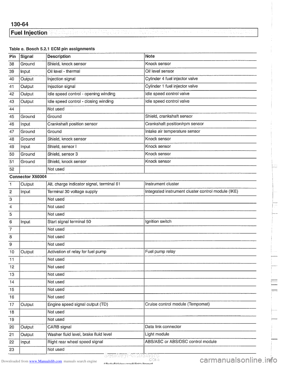
Table e. Bosch 5.2.1 ECM pin assignments
Pin
I~iqnal 1 Description 1 Note
I I I
46 llnput ICrankshaft position sensor Icrankshaft positionlrpm sensor
38
39
40
41
42
43
44
45 Ground Input
Output
Output
Output
Output
Ground
47
48
49
50
51
Not used
I Not used
52
Shield, knock sensor
Oil level
- thermal
Injection signal
injection signal
Idle speed control - opening winding
Idle speed control - closing winding
Not used
Ground
Ground
-- Ground Input
Ground
Ground Not used Knock sensor
Oil level sensor
Cylinder
4 fuel injector
valve
Cylinder
1 fuel injector valve
Idle speed control valve
Idle speed control valve
Shield, crankshaft sensor
5
6
7
12 Not used
Ground
Intake air temperature sensor
Connector
X60004
8
9 10
11
14 1 1 Not used I
Shield, knock sensor
Shield, sensor
I
Shield, sensor 3
Shield, itnock sensor
Input
- Knoclc sensor
Knock sensor
Knock sensor
Knock sensor
Instrument cluster
Output
2 llnput l~erminal 30 voltage supply /Megrated instrument cluster control module (IKE)
Alt. charge indicator signal, terminal 61 1
Not used
Start signal terminal
50
Not used
15
16
17
18
Output
Ignition switch
Not used
Not used
Activation of relay for fuel pump
Not used
19
Fuel pump relay
Output Not used
I I I 20 loutput ICARB signal /Data link connector
Not
used
Not used
Engine speed signal output (TD)
Not used
Light module
21
Cruise control module (Tempomat)
22 llnput I Right rear wheel speed signal /ABS/ASC or ABSIDSC control module
Oulput
Washer
fluid level,
brake fluid level
Page 469 of 1002
Downloaded from www.Manualslib.com manuals search engine
Fuel Injection I
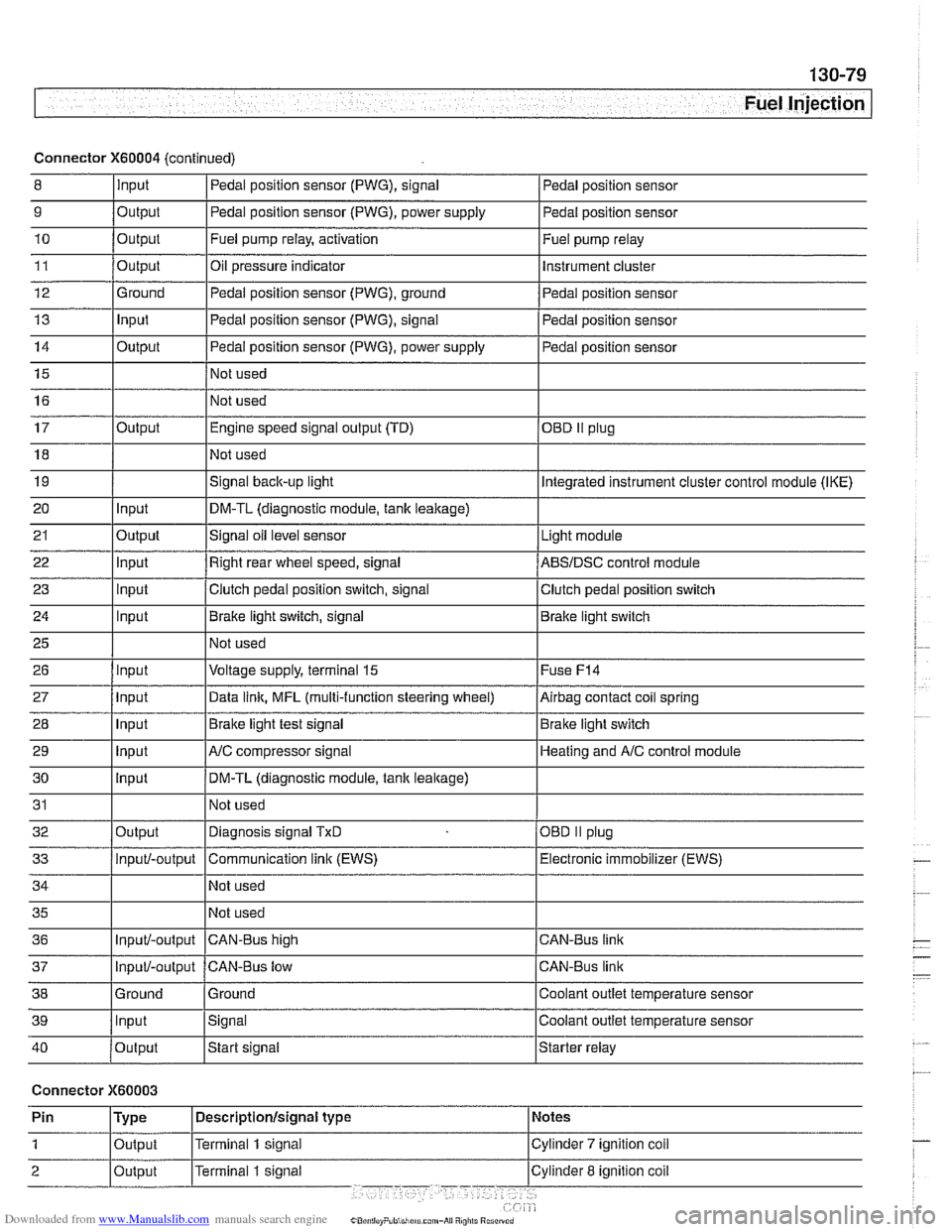
Connector X60004 (continued)
8 10
11
12
13
14
15
16
9
Output 0
Input
17
18
19
20
21
22
23
24
25
26
27
28
29
30
31
32
33
34
35
36
39
llnput lsignal l~oolant outlet temperature sensor
Output
Output
Ground
Input
Output
I I - I
40 /output Istart signal Istarter relay
Pedal position sensor (PWG), signal
Output Input
Output
input
Input
Input
Input
Input
Input
input
Input
Output
Input/-output
Input/-output
37
Connector X60003
Pedal position sensor
Fuel pump relay, activation
Oil pressure indicator Pedal position sensor (PWG), ground
Pedal position sensor (PWG), signal
Pedal position sensor (PWG), power supply
Not used
Not used Fuel
pump relay
Instrument cluster
Pedal position sensor
Pedal position sensor
Pedal position sensor
Engine speed signal output (TD)
Not used
Signal
back-up light
DM-TL (diagnostic module,
tank leakage)
Signal oil level sensor
Right rear wheel speed, signal
Clutch pedal position switch, signal
Brake light switch, signal
Not used
Voltage supply, terminal
15
Data link, MFL (multi-function steering wheel)
Brake light test signal
AJC compressor signal
DM-TL (diagnostic module, tank
leakage)
Not used
Diagnosis signal
TxD
Communication link (EWS)
Not used
Not used
CAN-BUS hiqh
38 1 Ground l~round I Coolant outlet temperature sensor
OED II plug
Integrated instrument cluster control module (IKE)
Light module
ABSIDSC control module
Clutch pedal position switch
Brake light switch
Fuse
F14
Airbag contact coil spring
Brake light switch
Heating and
A/C control module
OBD
II plug
Electronic immobilizer (EWS)
CAN-Bus link
CAN-Bus link
Input/-output CAN-Bus low
Page 630 of 1002
Downloaded from www.Manualslib.com manuals search engine
300-1 0
/Suspension, Steering and Brakes - General
The steering system features variable power assist provided
by an engine-driven hydraulic pump.
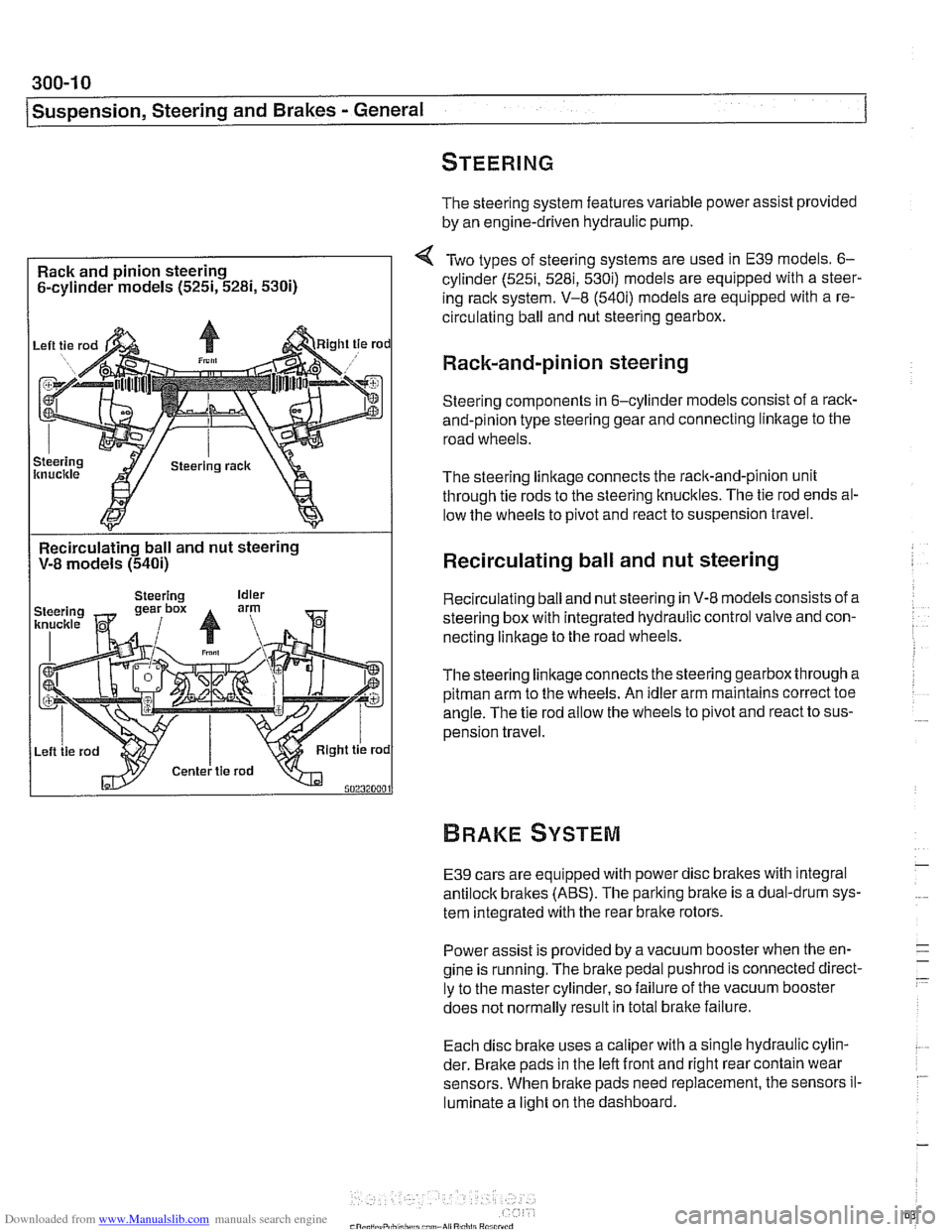
Rack and pinion steering
6-cylinder models
(525i, 5281, 5300
Two types of steering systems are used in E39 models. 6-
cylinder (525i, 5281, 530i) models are equipped with a steer-
ing rack system. V-8
(540i) models are equipped with a re-
circulating ball and nut steering gearbox.
Rack-and-pinion steering
Steering components in 6-cylinder models consist of a rack-
and-pinion type steering gear and connecting linltage to the
road wheels.
The steering linkage connects the rack-and-pinion unit
through tie rods to the steering knucltles. The tie rod ends al-
low the wheels to pivot and react to suspension travel.
Recirculating ball and nut steering
V-8 models
(540i)
I
Recirculating ball and nut steering
Recirculating ball and nut steering in V-8 models consists of a
steering box with integrated hydraulic control valve and con-
necting linkage to the road wheels.
Thesteering linkageconnects the steering gearbox through a
pitman arm to the wheels. An idler arm maintains correct toe
angle. The tie rod allow the wheels to pivot and react to sus-
pension travel.
E39 cars are equipped with power disc brakes with integral
antilock brakes (ABS). The parking bralte is a dual-drum sys-
tem integrated with the rear brake rotors.
Power assist is provided by a vacuum booster when the en-
gine is running. The brake pedal
pushrod is connected direct-
ly to the master cylinder, so failure of the vacuum booster
does not normally result in total
bralte failure.
Each disc bralte uses a caliper with a single hydraulic cylin-
der. Brake pads in the left front and right rear contain wear
sensors. When brake pads need replacement, the sensors il-
luminate a light on the dashboard.
Page 632 of 1002
Downloaded from www.Manualslib.com manuals search engine
300-1 2
I Sus~ension, Steerincl and Brakes - General
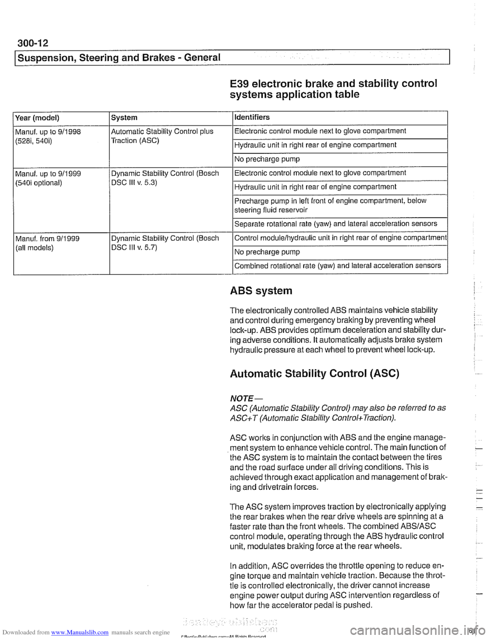
E39 electronic brake and stability control
systems application table
(528i, 54bi) Traction (ASC) I Hydraulic unit in right rear of engine compartment 1
Identifiers
Year (model)
I No precharge pump 1
Manuf. up to 911998 l~utomatic Stability Control plus I Electronic control module next to glove compartment
System
Precharge pump in
lefl front of engine compartment, below
steering fluid reservoir
Separate rotational rate (yaw) and lateral acceleration sensors
I I
Combined rotational rate (yaw) and lateral acceleration sensors
Electronic control
module next to glove compartment
Hydraulic unit in right rear of engine compartment
Manuf. up to 911999
(540i optional)
I I
ABS system
Dynamic Stability Control (Bosch
DSC
Ill v. 5.3)
The electronically controlled
ABS maintains vehicle stability
and control during emergency braking by preventing wheel
lock-up.
ABS provides optimum deceleration and stability dur-
ing adverse conditions. It automatically adjusts brake system
hydraulic pressure at each wheel to prevent wheel lock-up.
Control
moduleihydraulic unit
in right rear of engine compartment
No precharge pump
Manuf. from
911999
(all models)
Automatic Stability Control (ASC)
Dynamic Stability Control (Boscli
DSC Ill v. 5.7)
NOJE-
ASC (Automatic Stability Control) may also be referred to as
ASCiT (Automatic Stability ControkTraction).
ASC works in conjunction with ABS and the engine manage-
ment system to enhance vehicle control. The main function of
the
ASC system is to maintain the contact between the tires
and the road surface under all driving conditions. This is
achieved through exact application and management of brak-
ing and drivetrain forces.
The
ASC system improves traction by electronically applying
the rear brakes when the rear drive wheels are spinning at a
faster rate than the front wheels. The combined
ABSIASC
control module, operating through the ABS hydraulic control
unit, modulates braking force at the rear wheels.
In addition,
ASC overrides the throttle opening to reduce en-
gine torque and maintain vehicle traction. Because the throt-
tle is controlled electronically, the driver cannot increase
engine power output during
ASC intervention regardless of
how far the accelerator pedal is pushed.
Page 633 of 1002
Downloaded from www.Manualslib.com manuals search engine
Suspension, Steering and Brakes - ~enerail
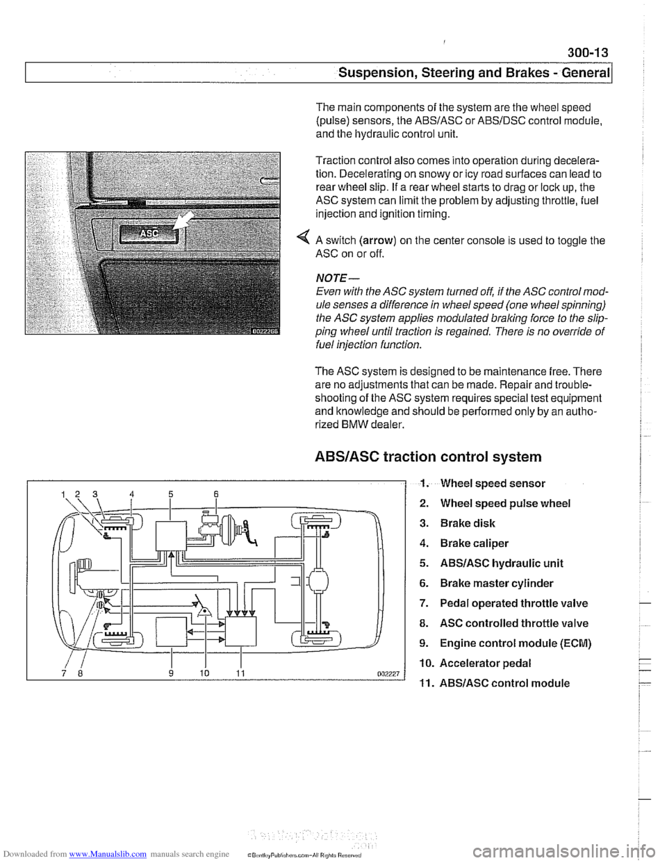
The main components of the system are the wheel speed
(pulse) sensors, the
ABSIASC or ABSIDSC control module,
and the hydraulic control unit.
Traction control also comes into operation during decelera-
tion. Decelerating on snowy or icy road surfaces can lead to
rear wheel slip. If a rear wheel starts to drag or lock up, the
ASC system can limit the problem by adjusting throttle, fuel
injection and ignition timing.
4 A switch (arrow) on the center console is used to toggle the
ASC on or off.
NOJE-
Even with the ASC system turned off, if the ASC control mod-
ule senses a difference in wheel speed (one wheel spinning)
the
ASC system applies modulated braling force to the slip-
ping wheel until traction is regained. There is no override of
fuelinjection function.
The ASC system is designed to be maintenance free. There
are no adjustments that can be made. Repair and trouble-
shooting of the ASC system requires special test equipment
and knowledge and should be performed only by an autho-
rized
BMW dealer.
ABSIASC traction
I 1.
control system
Wheel speed sensor
Wheel speed pulse wheel
Brake disk
Brake caliper
ABSIASC hydraulic unit
Brake master cylinder
Pedal operated throttle valve
ASC controlled throttle valve
Engine control module (ECM)
Accelerator pedal
ABSlASC control module
Page 641 of 1002
Downloaded from www.Manualslib.com manuals search engine
31 0-5
Front ~uspensionl
Front strut assembly, removing and
installing
- Raise car and remove front wheel.
WARNING-
Make sure that the car is firmly supported on jack stands de-
signed for the purpose. Place jack stands underneath struc-
tural chassis points.
Do not place jack stands under
suspension
parts.
- Unbolt bralte caliper assembly, lkeeping bralte hose connect-
ed. Secure brake caliper to body with wire. Do not let it hang
from brake hose. See
340 Brakes.
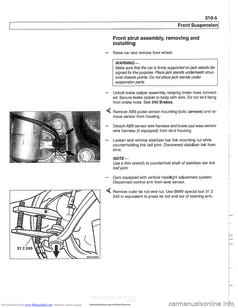
Remove ABS pulse sensor mounting bolts (arrows) and re-
move sensor from housing.
Detach ABS sensor wire harness and bralte pad wear sensor
wire harness (if equipped) from strut housing.
Loosen and remove stabilizer bar link mounting nut while
counterholding
link ball joint. Disconnect stabilizer link from
strut.
NOTE-
Use a thin wrench to counterhold shaft of stabilizer bar link
ball joint.
- Cars equipped with vertical headlight adjustment system:
Disconnect control arm from level sensor.
4 Remove outer tie rod end nut. Use BMW special tool 31 2
240 or equivalent to press tie rod end out of steering arm.
Page 648 of 1002
Downloaded from www.Manualslib.com manuals search engine
/~ront Susaension
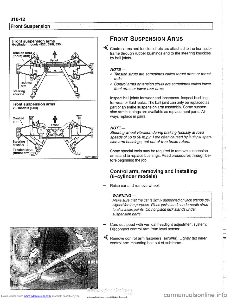
Front suspension arms FRONT SUSPENSION ARMS
Scyllnder models (5251,5281,530i)
Control arms and tension struts are attached to the front sub-
Front suspension arms V-8 models (5401)
frame through rubber bushings and to the steering ltnuckles
by ball joints.
NOTE-
Tension struts are sometimes called thrust arms or thrust
rods.
Control arms or tension struts are sometimes called lower
front arms or lower rear arms.
Inspect ball joints for wear and looseness. lnspect bushings
for wear or fluid
lealts. The ball joint can only be replaced as
part of an entire suspension arm assembly. Some suspen-
sion arm
bushinas are available as re~lacement Darts. Al-
ways replace in pairs
NOTE-
Steering wheel vibration during braking (usually at road
speeds of
50 to 60 m.p.h.) are often causedby faulty suspen-
sion arm bushings, not out-of-true brake rotors.
Some special tools may be required to remove suspension
arms and to replace bushings. Read procedures through be-
fore beginning the job.
Control arm, removing and installing
(6-cylinder models)
- Raise car and remove wheel
Male sure
that the car is firmly supported on jack stands de-
signed for the purpose. Place jack stands underneath struc-
tural chassis points. Do not place jack stands under
suspension
parfs.
Cars equipped with vertical headlight adjustment system:
Disconnect control arm from level sensor.
Remove control arm fasteners (arrows). Lightly tap inner
control arm mounting bolt out of subframe.