Alternator BMW 525i 2001 E39 Workshop Manual
[x] Cancel search | Manufacturer: BMW, Model Year: 2001, Model line: 525i, Model: BMW 525i 2001 E39Pages: 1002
Page 3 of 1002
Downloaded from www.Manualslib.com manuals search engine
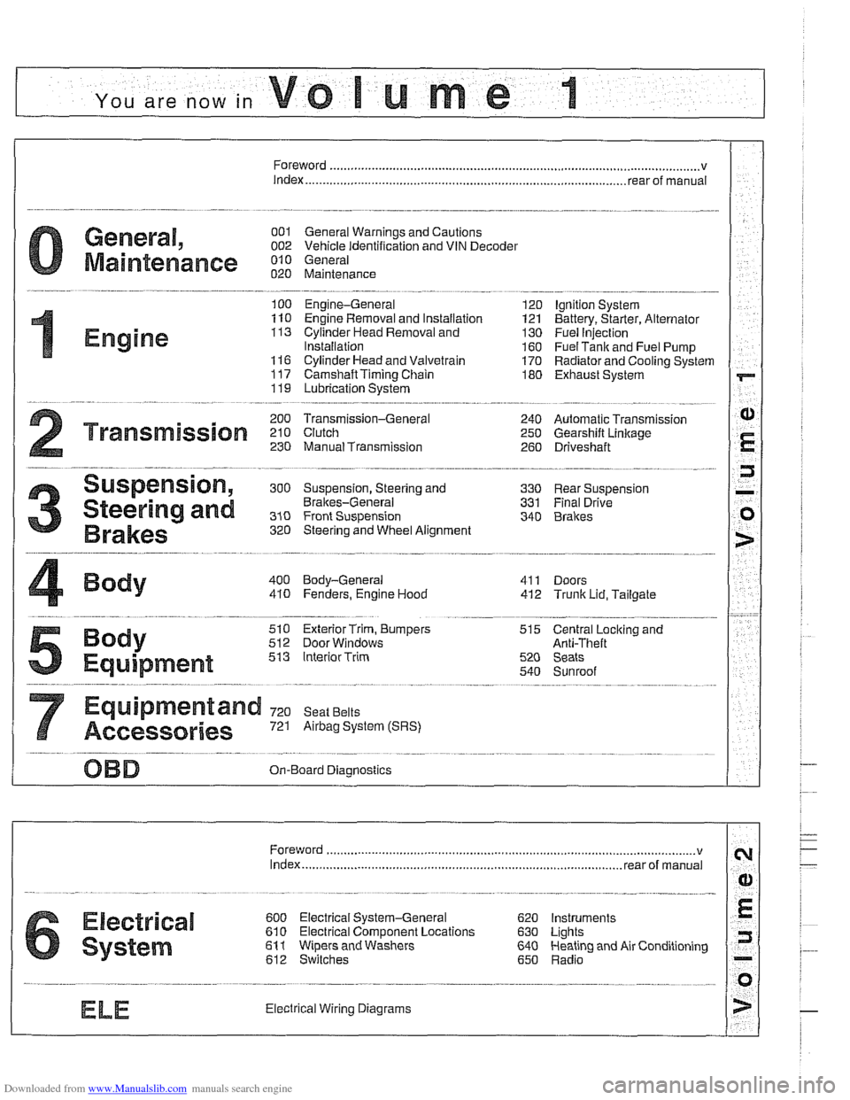
YOU are now in Volume I
I
Foreword ................... .. ........................................................................\
.......... v
Index
........................ .. ................................................................ rear of manual
General, 001 General Warnings and Cautions 002 Vehicle Identification and VIN Decoder
Maintenance OiO 020 Maintenance
Engine
100 Engine-General 110 Engine Removal and Installation
113 Cylinder Head Removal and
Installation
116 Cyiinder Head and Valvetrain 117 Camshaft Timing Chain
119 Lubrication System
200 Transmission-General
2 Transmission 210 clutch 230 ManualTransmission
I20 Ignition System
121 Battery, Starter, Alternator
130 Fuel Injection
160 Fuel Tank and Fuel Pump 170 Radiator and Cooling System
180 Exhaust System
240 Automatic Transmission
250 Gearshift Linkage 260 Driveshaft
Suspension, 300 Suspension, Steering and 330 Rear Suspension
Brakes-General 331 Final Drive
Steering and No Front Suspension 340 Brakes
320 Steering and Wheel Alignment
400 Body-General
410 Fenders, Engine Hood 411 Doors
412 Trunk Lid, Tailgate
510 Exterior Trim, Bumpers 512 Door Windows
Equipment 513 Interior Trim
7
Equipment and 720 seat Belts
Accessories 721 Airbag System (SRS)
OBD On-Board Diagnostics
. ............ ..
515 Central Lociting and
Anti-Theft
520 Seats 540 Sunroof
.................................................................... Foreword .............................. .. v
Index ................... .. ................................................................ rear of manual
Electrical
6 system
600 Electrical System-General 620 Instruments
610 Electrical Comoonent Locations 630 Liohts
611 wipers and washers 612 Switches eati in^ and Air Conditioning
Radio
. ........... ........ .........................
Electrical Wiring Diagrams
Page 48 of 1002
Downloaded from www.Manualslib.com manuals search engine
020-1 6
Maintenance
loose, hose is damaged, or connection is dirty or corroded.
Dried coolant has achalky appearance. Hoses should be firm
and springy. Replace any hose that is cracked, has become
soft and limp, or has been contaminated by oil.
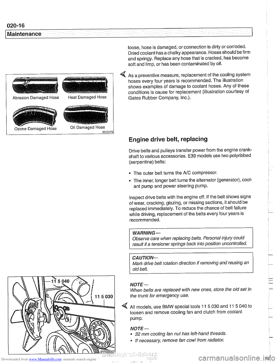
4 As a preventive measure, replacement of the cooling system
hoses every four years is recommended. The illustration
shows examples of damage to coolant hoses. Any of these
conditions is cause for replacement (illustration courtesy of
/ Abrasion Damaged Hose Heat Damaged Hose 1 Gates Rubber Company, I~c.).
Engine drive belt, replacing
Drive belts and pulleys transfer power from the engine crank-
shaft to various accessories.
E39 models use two polyribbed
(serpentine) belts:
The outer belt turns the
NC compressor.
0 The inner, longer belt turns the alternator (generator), cool-
ant pump and power steering pump.
Inspect drive belts with the engine off. If the belt shows signs
of wear, cracking, glazing, or missing sections, it should be
replaced
immediately. To reduce the chance of belt failure
while driving, replacement of the belts every four years is
recommended.
WARNING -
Observe care when replacing belts. Personal injury could
result if a tensioner springs back into position uncontrolled.
CA UTIOI\C
Mark drive belt rotation direction if removing and reusing an
old belt.
NOTE-
When belts are replaced with new ones, store the old set in
the trunk for emergency use.
All models, use
BMW special tools 11 5 030 and 11 5 040 to
loosen and remove cooling fan and clutch from coolant
pump.
NOTE-
32 mm cooling fan nut has left-hand threads
If necessary, remove fan cowl from radiator.
Page 51 of 1002
Downloaded from www.Manualslib.com manuals search engine
Maintenance
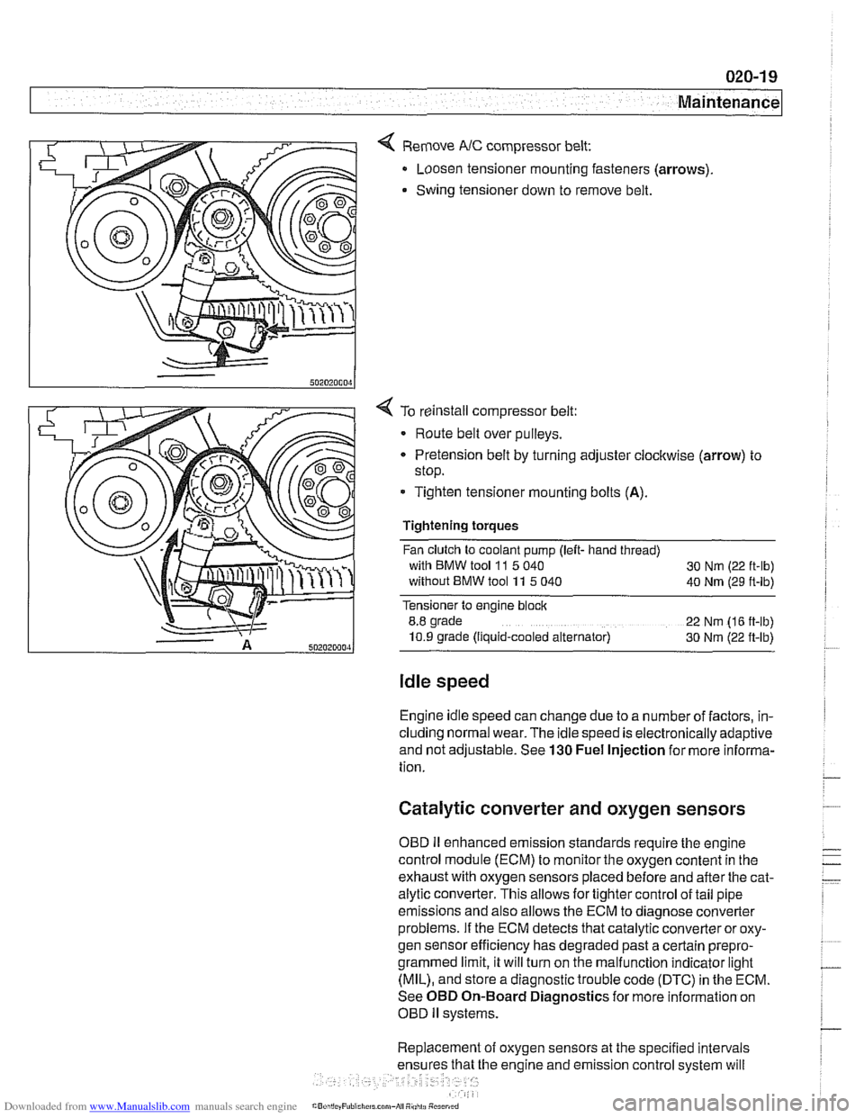
< Remove NC compressor belt:
Loosen tensioner mounting fasteners (arrows)
Swing tensioner down to remove belt.
4 To reinstall compressor belt:
Route belt over pulleys.
* Pretension belt by turning adjuster clockwise (arrow) to
stop.
- Tighten tensioner mounting bolts (A).
Tightening torques
Fan clutch to coolant pump (left- hand thread)
with BMW tool
11 5 040
30 Nm (22 ft-lb)
without BMW tool 11 5 040
40 Nm (29 ft-lb)
Tensioner to engine block
8.8 grade
22 Nm (16 ft-lb)
10.9 grade (Ilquid-cooled alternator) 30 Nm (22 ft-lb)
Idle speed
Engine idle speed can change due to a number of factors, in-
cluding normal wear. The idle speed is electronically adaptive
and not adjustable. See
130 Fuel Injection for more informa-
tion.
Catalytic converter and oxygen sensors
OBD II enhanced emission standards require the engine
control module (ECM) to monitor the oxygen content in the
exhaust with oxygen sensors placed before and after the cat-
alytic converter. This allows for tighter control of tail pipe
emissions and also allows the ECM to diagnose converter
problems. If the ECM detects that catalytic converter or oxy-
gen sensor efficiency has degraded past a certain
prepro-
grammed limit, it will turn on the malfunction indicator light
(MIL), and store a diagnostic trouble code (DTC) in the ECM.
See OBD On-Board Diagnostics for more information on
OBD
ll systems.
Replacement of oxygen sensors at the specified intervals
he engine and emission control system will
Page 56 of 1002
Downloaded from www.Manualslib.com manuals search engine
020-24
Maintenance
tions. In general, replacement batteries should always be
rated equal or higher than the original battery.
The battery is held in place by a single hand screw and plate.
A secure battery hold-down is important in order to prevent
vibrations and road shoclt from damaging the battery.
CAUTION-
Prior to disconnecting the baitem read the battery discon-
nection cautions given in
001 General Cautions and
Warnings.
NOTE-
Always disconnect the negative (-) cable first, and connect
it last. While changing the battery, clean away any corro-
sion in or around the battery tray
More battery and charging system information is in 121
Battery, Alternator, Starter.
Brake fluid, replacing
Brake fluid absorbs moisture easily, and moisture in the fluid
affects bralte performance and reliability. This is why
BMW
strictly recommends replacing the bralte fluid every two
years. When replacing or adding bralte fluid, use only new
fluid from previously unopened containers. Do not use brake
fluid that has been bled from the system, even
if it is brand
new. Use only DOT
4 brake fluid.
NOTE-
See 340 Brakes for brake fluid flushing procedures.
Brake pad 1 rotor wear, checking
Disc brakes are fitted at all four wheels. Although the brakes
are equipped with a brake pad warning system, the system
only monitors one wheel per axle. Pad thickness should be
checked whenever wheels are off or brake
worlt is being
done.
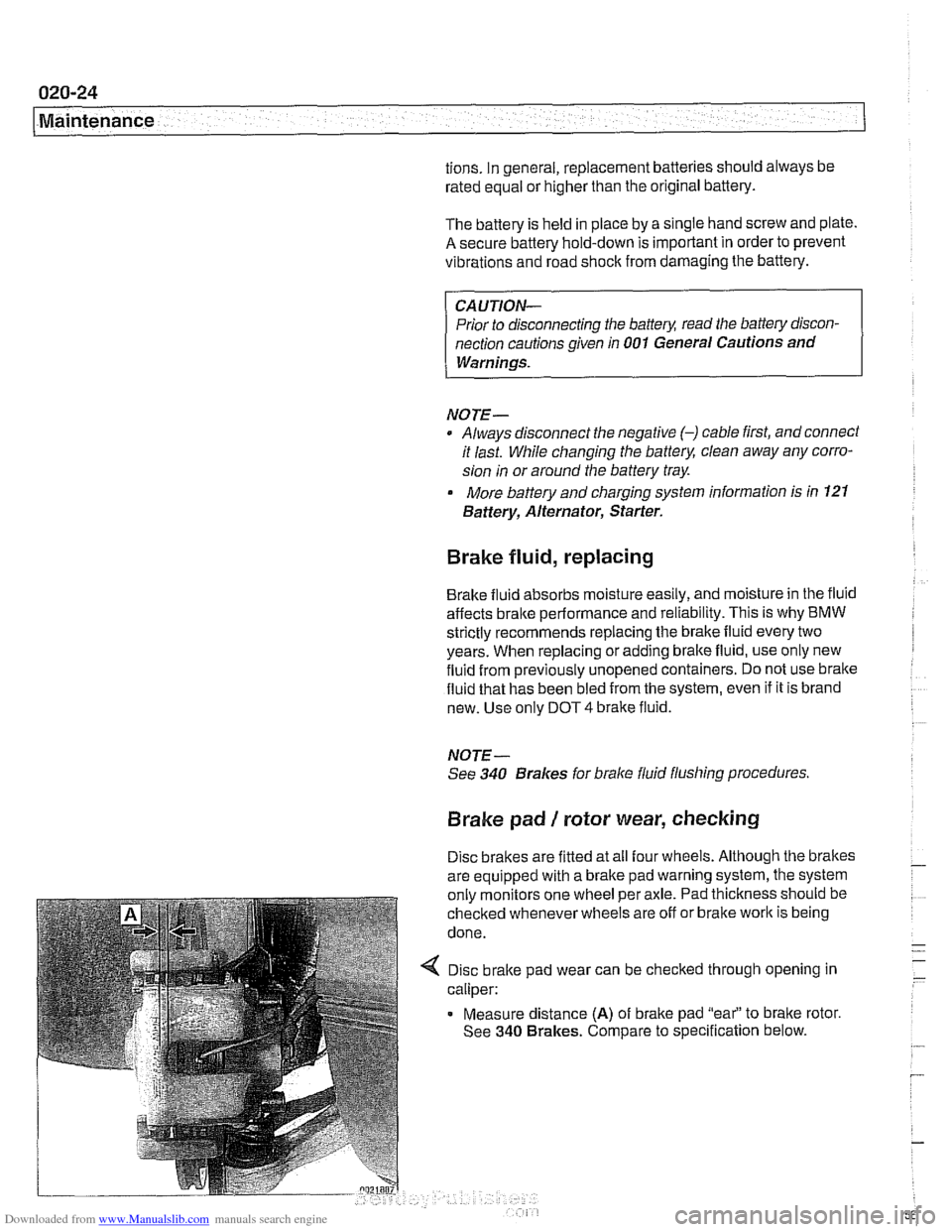
4 Disc brake pad wear can be checked through opening in
caliper:
Measure distance
(A) of brake pad "eai' to bralte rotor.
See
340 Brakes. Compare to specification below.
Page 70 of 1002
Downloaded from www.Manualslib.com manuals search engine
100-4
I Engine-General
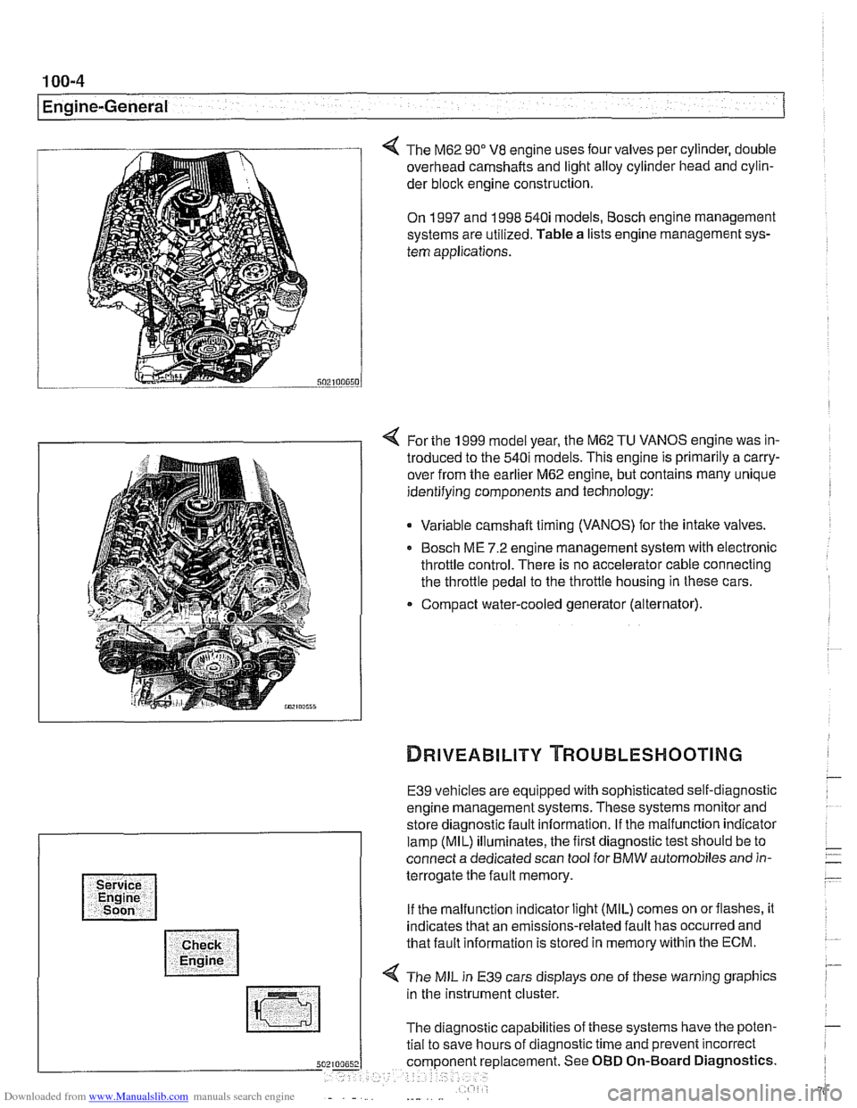
The M62 90" V8 engine uses four valves per cylinder, double
overhead camshafts and light alloy cylinder head and cylin-
der
bloclc engine construction.
On 1997 and 1998 540i models, Bosch engine management
systems are utilized. Table a lists engine management sys-
tem applications.
4 For the 1999 model year, the M62 TU VANOS engine was in-
troduced to the 540i models. This engine is primarily a carry-
over from the earlier M62 engine, but contains many unique
identifying components and technology:
Variable camshaft timing (VANOS) for the intake valves.
Bosch ME 7.2 engine management system with electronic
throttle control. There is no accelerator cable connecting
the throttle pedal to the throttle housing in these cars.
Compact water-cooled generator (alternator).
E39 vehicles are equipped with sophisticated self-diagnostic
engine management systems. These systems monitor and
store diagnostic fault information. If the malfunction indicator
lamp (MIL) illuminates, the first diagnostic test should be to
connect a dedicated scan tool for BMW automobiles and in-
terrogate the fault memory.
If the malfunction indicator light (MIL) comes on orflashes, it
indicates that an emissions-related fault has occurred and
that fault information is stored in memory within the ECM.
4 The MIL in E39 cars displays one of these warning graphics
in the instrument cluster.
The diagnostic capabilities of these systems have the poten-
tial to save hours of diagnostic time and prevent incorrect
5 placement. See OBD On-Board Diagnostics.
Page 71 of 1002
Downloaded from www.Manualslib.com manuals search engine
Two common causes of driveability problems are incorrect
system voltage and bad grounds.
System voltage
Digital motor electronics (DME) requires that the system (bat-
tery) voltage be maintained within a narrow range of DC volt-
age.
DC voltage levels beyond or below the operating range,
or any
AIC voltage in the electrical system can cause havoc.
When troubleshooting an illuminated MIL, make sure the bat-
tery is fully charged and capable of delivering all its power to
the electrical system. An undercharged battery can amplify
AIC alternator output ripple.
To
make a quick check of the battery charge, measure the
voltage across the battery terminals with all cables attached
and the ignition off.
Afully charged battery will measure 12.6
volts or slightly more, compared to 12.1 5 volts for a battery
with a 25% charge.
The DME system operates at low voltage and current levels,
making it sensitive to small increases in resistance. The elec-
trical system is routinely subjected to corrosion, vibration and
wear, so faults or corrosion in the wiring harness and connec-
tors are not uncommon. Check the battery terminals
forcorro-
sion or loose cable connections. See 121 Battery, Starter,
Alternator for additional information.
If a battery cable connection has no
v~sible faults but is still
suspect, measure the voltage drop across the connection. A
large drop indicates excessive resistance, meaning that the
connection is corroded, dirty, or damaged. Clean or repairthe
connection and retest.
NOTE-
For instructions on conducting a voltage drop test and other
general electrical troubleshooting information, see
600 Elec-
trical System-General.
Visually inspect all wiring, connectors, switches and fuses in
the system. Loose or damaged connectors can cause inter-
mittent problems, especially the small terminals in the ECM
connectors. Disconnect the wiring harness connectors to
check for corrosion, and use electrical cleaning spray to re-
move contaminants.
Main grounds
Good grounds are critical to proper DME operation. If a
ground connection has no visible faults but is still suspect.
measure the voltage drop across the connection. A large volt-
age drop means high resistance. Clean or repair the connec-
tion and retest.
LBuntr.yP~sbhnllcn.can#-AII A,~iltl Rcsrwsd
Page 74 of 1002
Downloaded from www.Manualslib.com manuals search engine
I Engine Removal and Installation
Engine removal and installation are covered in this repail
group.
See 100 Engine-General for engine identification details
and engine codes.
Transmission removal is required for all models before the
engine can be removed. This is best accomplished with the
car raised on an automotive lift. For additional procedures re-
quired during engine removal, refer to the following repair
groups:
020 Maintenance
0 121 Battery, Alternator, Starter
170 Radiator and Cooling System
180 Exhaust System
4 230 Manual Transmission
0 240 Automatic Transmission
410 Fenders, Engine Hood
Special tools
Some special tools are required for engine removal and in-
stallation. Be sure to have the necessary equipment on hand
before starting the job.
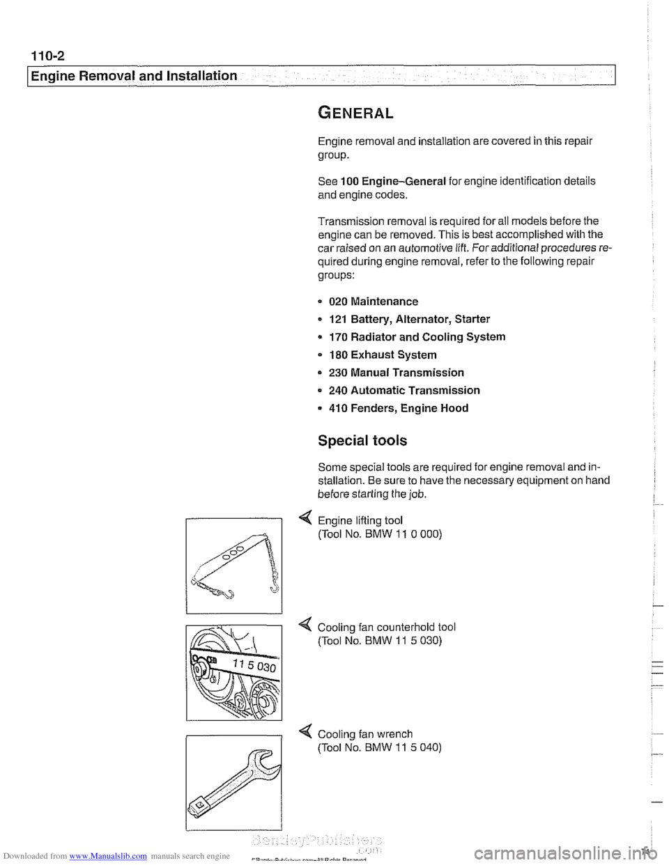
Engine lifting tool
(Tool No. BMW
11 0 000)
4 Cooling fan counterhold tool
(Tool No. BMW
11 5 030)
< Cool~ng fan wrench
(Tool No. BMW
11 5 040)
Page 82 of 1002
Downloaded from www.Manualslib.com manuals search engine
.-
-6val and Installation -
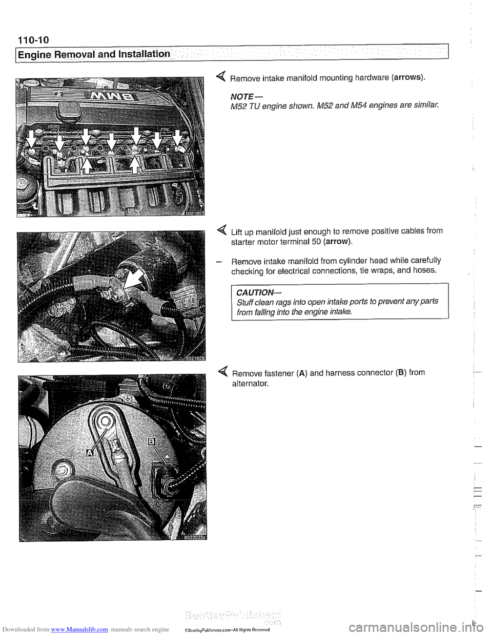
< Remove intake manifold mounting hardware (arrows).
NOTE-
M52 TU engine shown. M52 and M54 engines are similar.
Liit up manifold just enough to remove positive cables from
starter motor terminal
50 (arrow).
- Remove intake manifold from cylinder head while carefully
checking for electrical connections, tie wraps, and hoses.
CAUTION-
Stuff clean rags into open intake ports to prevent any parts
from falling into the engine intake.
4 Remove fastener (A) and harness connector (B) from
alternator.
Page 83 of 1002
Downloaded from www.Manualslib.com manuals search engine
Engine Removal and installatid
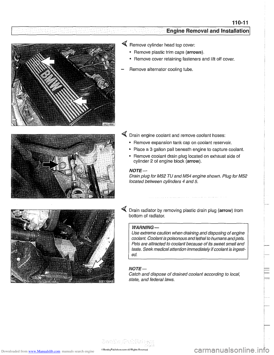
4 Remove cylinder head top cover:
Remove plastic trim caps
(arrows).
Remove cover retaining fasteners and lifl off cover.
- Remove alternator cooling tube.
4 Drain engine coolant and remove coolant hoses:
* Remove expansion tank cap on coolant reservoir.
Place a
3 gallon pail beneath engine to capture coolant,
* Remove coolant drain plug located on exhaust side of
cylinder
2 of engine block (arrow).
NOTE-
Drain plug for M52 TU and M54 engine shown. Plug for M52
located between cylinders 4 and 5.
Drain radiator by removing plastic drain plug (arrow) from
bottom of radiator.
WARNING-
Use extreme caution when draining and disposing of engine
coolant Coolant is poisonous andlethal to humans andpets.
Pets are attracted to coolant because of its sweet smell and
taste. Seek medical attention immediately if coolant is ingest-
ed.
NOTE-
Catch and dispose of drained coolant according to local,
state, and federal laws.
Page 92 of 1002
Downloaded from www.Manualslib.com manuals search engine
11 0-20
Engine Removal and Installation
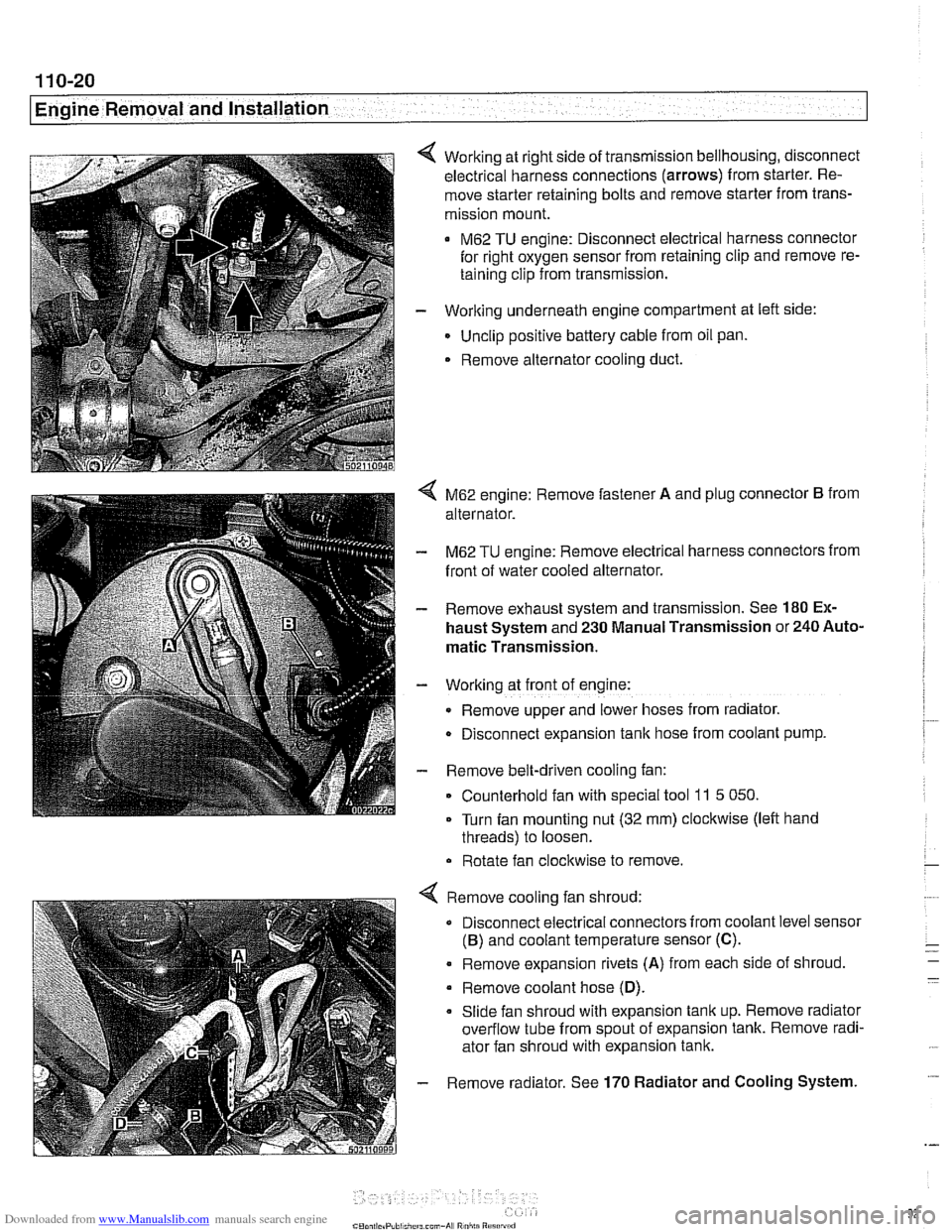
Working at right side of transmission bellhousing, disconnect
electrical harness connections (arrows) from starter. Re-
move starter retaining bolts and remove starter from trans-
mission mount.
M62 TU engine: Disconnect electrical harness connector
for right oxygen sensor from retaining clip and remove re-
taining clip from transmission.
- Working underneath engine compartment at left side:
Unclip positive battery cable from oil pan.
. Remove alternator cooling duct.
4 M62 engine: Remove fastener A and plug connector B from
alternator.
- M62 TU engine: Remove electrical harness connectors from
front of water cooled alternator.
- Remove exhaust system and transmission. See 180 Ex-
haust System and 230 Manual Transmission or 240 Auto-
matic Transmission.
- Working at front of engine:
Remove upper and lower hoses from radiator.
D~sconnect expansion tank hose from coolant pump.
- Remove belt-driven cooling fan:
Counterhold fan with special tool
11 5 050.
Turn fan mounting nut (32 mm) clockwise (left hand
threads) to loosen.
Rotate fan clockwise to remove.
Remove cooling fan shroud:
Disconnect electrical connectors from coolant level sensor
(B) and coolant temperature sensor (C).
. Remove expansion rivets (A) from each side of shroud
Remove coolant hose
(D).
Slide fan shroud with expansion tank up. Remove radiator
overflow tube from spout of expansion tank. Remove radi-
ator fan shroud with expansion tank.
Remove radiator. See
170 Radiator and Cooling System.