sensor BMW 528i 1997 E39 Workshop Manual
[x] Cancel search | Manufacturer: BMW, Model Year: 1997, Model line: 528i, Model: BMW 528i 1997 E39Pages: 1002
Page 633 of 1002
Downloaded from www.Manualslib.com manuals search engine
Suspension, Steering and Brakes - ~enerail
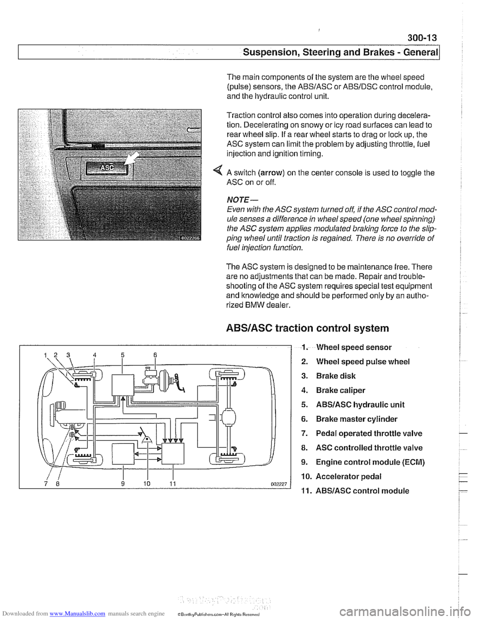
The main components of the system are the wheel speed
(pulse) sensors, the
ABSIASC or ABSIDSC control module,
and the hydraulic control unit.
Traction control also comes into operation during decelera-
tion. Decelerating on snowy or icy road surfaces can lead to
rear wheel slip. If a rear wheel starts to drag or lock up, the
ASC system can limit the problem by adjusting throttle, fuel
injection and ignition timing.
4 A switch (arrow) on the center console is used to toggle the
ASC on or off.
NOJE-
Even with the ASC system turned off, if the ASC control mod-
ule senses a difference in wheel speed (one wheel spinning)
the
ASC system applies modulated braling force to the slip-
ping wheel until traction is regained. There is no override of
fuelinjection function.
The ASC system is designed to be maintenance free. There
are no adjustments that can be made. Repair and trouble-
shooting of the ASC system requires special test equipment
and knowledge and should be performed only by an autho-
rized
BMW dealer.
ABSIASC traction
I 1.
control system
Wheel speed sensor
Wheel speed pulse wheel
Brake disk
Brake caliper
ABSIASC hydraulic unit
Brake master cylinder
Pedal operated throttle valve
ASC controlled throttle valve
Engine control module (ECM)
Accelerator pedal
ABSlASC control module
Page 641 of 1002
Downloaded from www.Manualslib.com manuals search engine
31 0-5
Front ~uspensionl
Front strut assembly, removing and
installing
- Raise car and remove front wheel.
WARNING-
Make sure that the car is firmly supported on jack stands de-
signed for the purpose. Place jack stands underneath struc-
tural chassis points.
Do not place jack stands under
suspension
parts.
- Unbolt bralte caliper assembly, lkeeping bralte hose connect-
ed. Secure brake caliper to body with wire. Do not let it hang
from brake hose. See
340 Brakes.
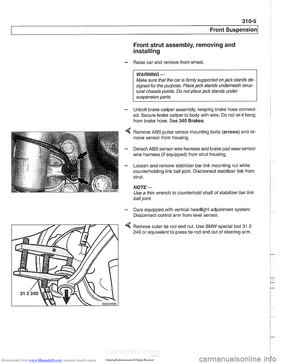
Remove ABS pulse sensor mounting bolts (arrows) and re-
move sensor from housing.
Detach ABS sensor wire harness and bralte pad wear sensor
wire harness (if equipped) from strut housing.
Loosen and remove stabilizer bar link mounting nut while
counterholding
link ball joint. Disconnect stabilizer link from
strut.
NOTE-
Use a thin wrench to counterhold shaft of stabilizer bar link
ball joint.
- Cars equipped with vertical headlight adjustment system:
Disconnect control arm from level sensor.
4 Remove outer tie rod end nut. Use BMW special tool 31 2
240 or equivalent to press tie rod end out of steering arm.
Page 648 of 1002
Downloaded from www.Manualslib.com manuals search engine
/~ront Susaension
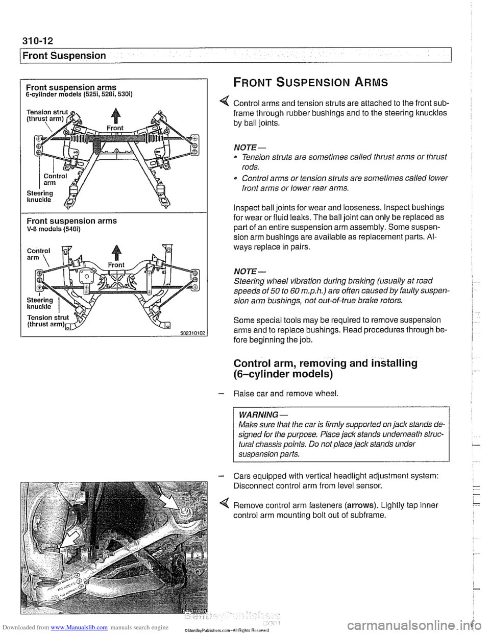
Front suspension arms FRONT SUSPENSION ARMS
Scyllnder models (5251,5281,530i)
Control arms and tension struts are attached to the front sub-
Front suspension arms V-8 models (5401)
frame through rubber bushings and to the steering ltnuckles
by ball joints.
NOTE-
Tension struts are sometimes called thrust arms or thrust
rods.
Control arms or tension struts are sometimes called lower
front arms or lower rear arms.
Inspect ball joints for wear and looseness. lnspect bushings
for wear or fluid
lealts. The ball joint can only be replaced as
part of an entire suspension arm assembly. Some suspen-
sion arm
bushinas are available as re~lacement Darts. Al-
ways replace in pairs
NOTE-
Steering wheel vibration during braking (usually at road
speeds of
50 to 60 m.p.h.) are often causedby faulty suspen-
sion arm bushings, not out-of-true brake rotors.
Some special tools may be required to remove suspension
arms and to replace bushings. Read procedures through be-
fore beginning the job.
Control arm, removing and installing
(6-cylinder models)
- Raise car and remove wheel
Male sure
that the car is firmly supported on jack stands de-
signed for the purpose. Place jack stands underneath struc-
tural chassis points. Do not place jack stands under
suspension
parfs.
Cars equipped with vertical headlight adjustment system:
Disconnect control arm from level sensor.
Remove control arm fasteners (arrows). Lightly tap inner
control arm mounting bolt out of subframe.
Page 649 of 1002
Downloaded from www.Manualslib.com manuals search engine
Front Suspension
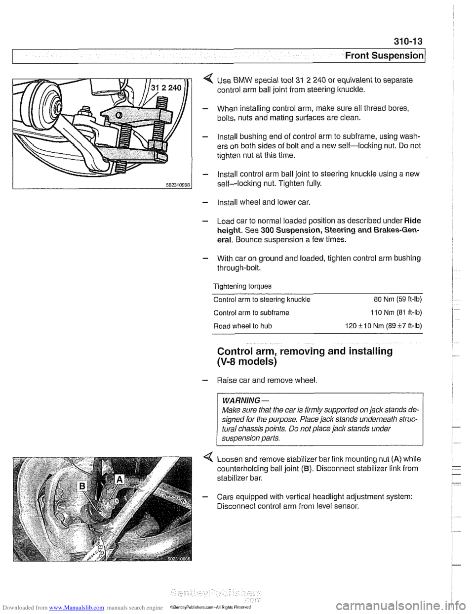
< Use BMW special tool 31 2 240 or equivalent to separate
control arm ball joint from steering ltnuckle.
- When installing control arm, make sure all thread bores.
bolts, nuts and mating surfaces are clean.
- Install bushing end of control arm to subframe, using wash-
ers on both sides of bolt and a new self-locking nut. Do not
tighten nut at this time.
- Install control arm ball joint to steering lknucltle using a new
self-locking nut. Tighten fully.
- Install wheel and lower car.
- Load car to normal loaded position as described under Ride
height. See
300 Suspension, Steering and Brakes-Gen-
eral. Bounce suspension a few times.
- With car on ground and loaded, tighten control arm bushing
through-bolt.
Tightening torques
Control arm to steering ltnuckle
80 Nm (59 ft-lb)
Control arm to subframe 110 Nm (81 It-lb)
Road wheel to hub 120ilO Nm (8957 it-lb)
Control arm, removing and installing
(V-8 models)
- Raise car and remove wheel
WARNING-
Make sure that the car is firmly supported on jack stands de-
signed for the purpose. Place jack stands underneath struc-
tural
cliassis points. Do not place jack stands under
suspension parts.
Loosen and remove stabilizer bar link mounting nut
(A) while
counterholding ball joint
(B). Disconnect stabilizer link from
stabilizer bar.
- Cars equipped with vertical headlight adjustment system:
Disconnect control arm from level sensor.
Page 655 of 1002
Downloaded from www.Manualslib.com manuals search engine
Front Suspension
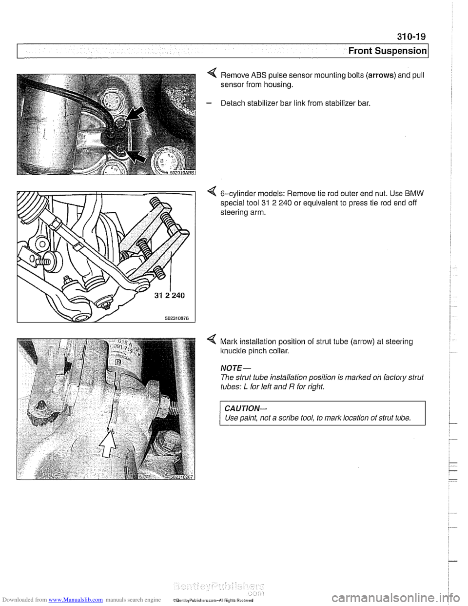
4 Remove ABS pulse sensor mounting bolts (arrows) and pull
sensor from housing.
- Detach stabilizer bar link from stabilizer bar.
4 6-cylinder models: Remove tie rod outer end nut. Use BMW
special tool
31 2 240 or equivalent to press tie rod end off
steering arm.
4 Mark installalion position of strut tube (arrow) at steering
knuckle pinch collar.
NOTE-
The strut tube installation position is marked on factory strut
tubes:
L for left and R for right.
CAUTION-
Use paint, not a scribe tool, to mark location of strut tube.
Page 668 of 1002
Downloaded from www.Manualslib.com manuals search engine
320-1 0
Steering and Wheel Alignment
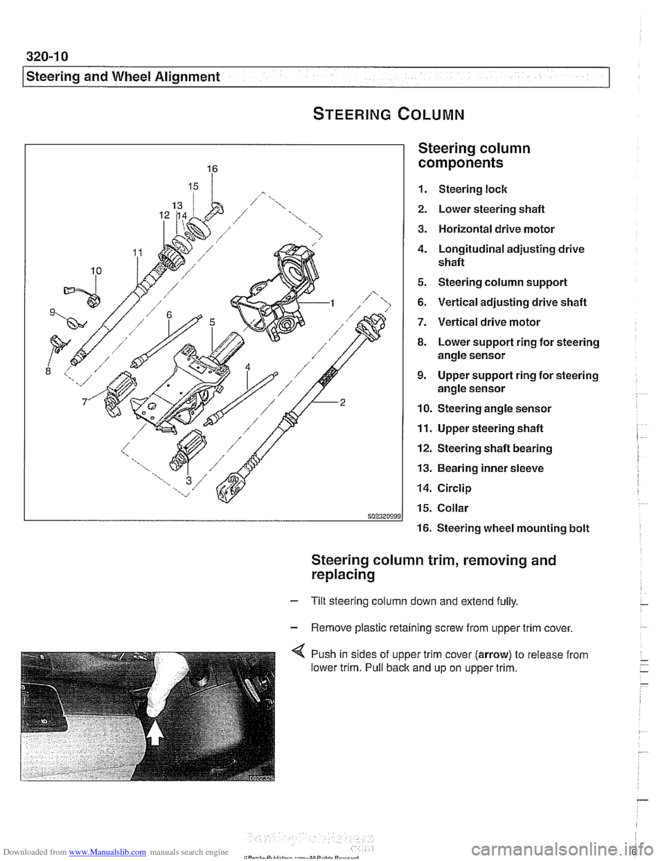
Steering column
components
1. Steering lock
2. Lower steering shafl
3. Horizontal drive motor
4. Longitudinal adjusting drive
shafl
5. Steering column support
6. Vertical adjusting drive shafl
7. Vertical drive motor
8. Lower support ring for steering
angle sensor
9. Upper support ring for steering
angle sensor
10. Steering angle sensor
11. Upper steering shafl
12. Steering shafl bearing
13. Bearing inner sleeve
14. Circlip
15. Collar
16. Steering wheel mounting bolt
Steering column trim, removing and
replacing
- Tilt steering column down and extend fully.
- Remove plastic retaining screw from upper trim cover,
4 Push in sides of upper trim cover (arrow) to release from
lower trim. Pull back and up on upper trim.
Page 672 of 1002
Downloaded from www.Manualslib.com manuals search engine
320-1 4
Steering and Wheel Alignment
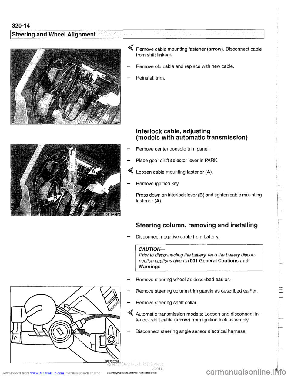
Remove cable mounting fastener (arrow). Disconnect cable
from shift
linkage.
Remove old cable and replace with new cable.
Reinstall trim.
Interlock cable, adjusting
(models with automatic transmission)
- Remove center console trim panel.
- Place gear shift selector lever in PARK.
4 Loosen cable mounting fastener (A).
- Remove ignition key.
- Press down on interlock lever (B) and tighten cable mounting
fastener (A).
Steering column, removing and installing
- Disconnect negative cable from battery.
CAUTIOI\C
Prior to disconnecting the battea read the battery discon-
nection cautions given
in 001 General Cautions and
Warninqs.
- Remove steering wheel as described earlier.
m
- Remove steering column trim panels as described earlier.
' \L/>I - Remove steerinq shaft collar
Automatic transmission models: Loosen and disconnect in-
terlock shift cable (arrow) from ignition lock assembly.
4 - Disconnect steering angle sensor electrical harness.
Page 674 of 1002
Downloaded from www.Manualslib.com manuals search engine
I Steering and Wheel Alignment
- Installation is reverse of removal, noting the following:
Replace shear bolts at steering column mounting bracket.
Tighten until bolt heads shear off.
Make sure
interlock cable snaps into place.
When installing column top trim panel, replace expansion
nut for trim retaining screw.
NOTE-
The steering angle sensor must be coded using a BMW scan
tool if it has been replaced.
A steering angle offset check
must then be carried out using the same
BMW scan tool.
CAUTION-
Check steering system for freedom of movement through en-
tire steering column
adiustment range.
Tightening torques Steering shaft coupler
to steering shaft 25 Nm (18 ft-lb)
(replace bolt)
Steering column to body
22 Nm (16 ft-lb)
Steering column adjustment motors,
removing and installing
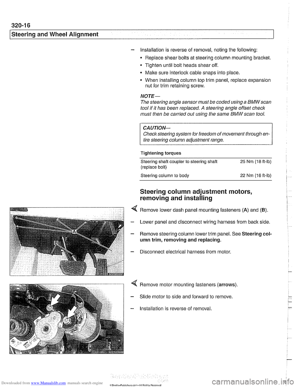
Remove lower dash panel mounting fasteners (A) and (B).
- Lower panel and disconnect wiring harness from back side.
- Remove steering column lower trim panel. See Steering col-
umn trim, removing and replacing.
- Disconnect electrical harness from motor.
Remove motor mounting fasteners (arrows)
Slide motor to side and forward to remove.
Installation is reverse of removal.
Page 697 of 1002
Downloaded from www.Manualslib.com manuals search engine
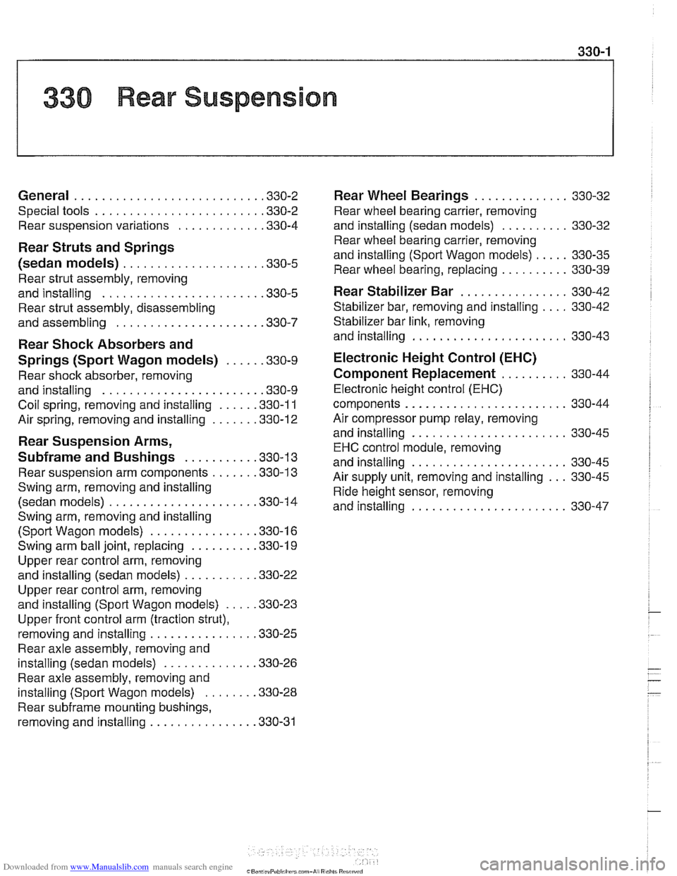
330 Rear Suspension
General . . . . . . . . . . . . . . . . . . . . . . . . . . . ,330-2
Special tools . . . . . . . . . . . . . . . . . . . . . . . . ,330-2
Rear suspension variations . . . . . . . . . . . . ,330-4
Rear Struts and Springs
(sedan models)
. . . . . . . . . . . . . . . . . . . . ,330-5
Rear strut assembly, removing
and installing
. . . . . . . . . . . . . . . . . . . . . . . ,330-5
Rear strut assembly, disassembling
and assembling
. . . . . . . . . . . . . . . . . . . . . ,330-7
Rear Shock Absorbers and
Springs (Sport Wagon models)
. . . . . ,330-9
Rear shock absorber, removing
and installing
. . . . . . . . . . . . . . . . . . . . . . . ,330-9
Coil spring, removing and installing . . . . . ,330-1 1
Air spring, removing and installing
. . . . . . ,330-12
Rear Suspension Arms,
Subframe and Bushings . . . . . . . . . . ,330-13
Rear suspension arm components . . . . . . ,330-1 3
Swing arm, removing and installing (sedan models)
. . . . . . . . . . . . . . . . . . . . . ,330-1 4
Swing arm, removing and installing (Sport Wagon models)
. . . . . . . . . . . . . . . ,330-16
Swing arm ball joint, replacing . . . . . . . . . ,330-1 9
Upper rear control arm, removing
and installing (sedan models)
. . . . . . . . . . .330-22
Upper rear control arm, removing
and installing (Sport Wagon models)
. . . . .330-23
Upper front control arm (traction strut),
removing and installing
. . . . . . . . . . . . . . . ,330-25
Rear axle assembly, removing and
installing (sedan models)
. . . . . . . . . . . . . ,330-26
Rear axle assembly, removing and
installing (Sport Wagon models)
. . . . . . . ,330-28
Rear subframe mounting bushings,
removing and installing
. . . . . . . . . . . . . . . .330-31
Rear Wheel Bearings . . . . . . . . . . .
Rear wheel bearing carrier, removing
and installing (sedan models)
. . . . . . .
Rear wheel bearing carrier, removing
and installing (Sport Wagon models)
. .
Rear wheel bearing, replacing . . . . . . .
Rear Stabilizer Bar
Stabilizer bar, removing and installing .
Stabilizer bar link, removing
and installing
. . . . . . . . . . . . . . . . . . . .
Electronic Height Control (EHC)
Component Replacement
. . . . . . .
Electronic height control (EHC)
components
.....................
Air compressor pump relay, removing
and installing
. . . . . . . . . . . . . . . . . . . .
EHC control module, removing
and installing
. . . . . . . . . . . . . . . . . . . .
Air supply unit, removing and installing
Ride height sensor, removing
and installing
. . . . . . . . . . . . . . . . . . . .
Page 710 of 1002
Downloaded from www.Manualslib.com manuals search engine
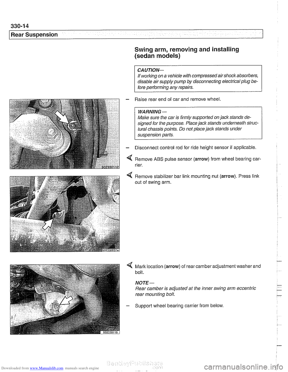
[Rear Suspension Swing arm, removing and installing
(sedan models)
CAUTION-
If working on a vehicle with compressed airshock absorbers,
disable air supply pump by disconnecting electrical plug be-
fore performing any repairs.
- Raise rear end of car and remove wheel
WARNING-
Make sure the car is firmly supported on jack stands de-
signed for the purpose. Place jack stands underneath struc-
tural chassis points. Do not place jack stands under
sus~ension Darts.
- Disconnect control rod for ride height sensor if applicable.
Remove
ABS pulse sensor (arrow) from wheel bearing car-
rier.
Remove stabilizer bar link mounting nut
(arrow). Press link
out of swing arm.
4 Mark location (arrow) of rear camber adjustment washer and
bolt.
NOTE-
Rear camber is adjusted at the inner swing arm eccentric
rear mounting bolt
- Support wheel bearing carrier from below.