Temperature sensor BMW 528i 1997 E39 Owner's Guide
[x] Cancel search | Manufacturer: BMW, Model Year: 1997, Model line: 528i, Model: BMW 528i 1997 E39Pages: 1002
Page 451 of 1002
Downloaded from www.Manualslib.com manuals search engine
-. -
Fuel Injection
I 68 1 / Not used
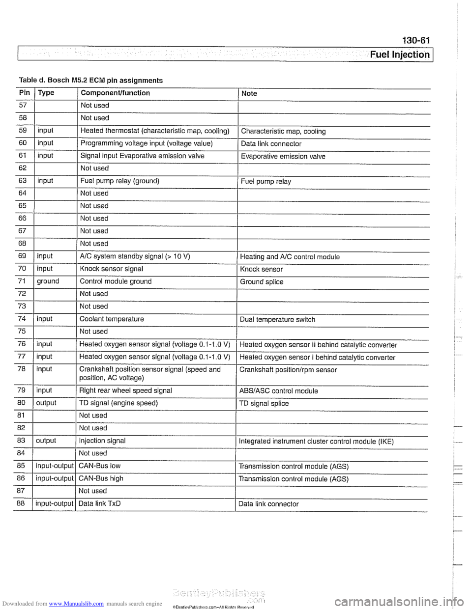
Table
d. Bosch
M5.2 ECM pin assignments
I I I
69 1 input I AIC system standby signal (> 10 V) 1 Heating and AIC control module
Pin
57
58
59
60
61
62
63
64
65 66
67
Type
input
input
input
input
I 70
72
73
74
Componentlfunction
Not used
Not used
Heated thermostat (characteristic map, cooling)
Programming voltage input (voltage
value)
Signal input Evaporative emission valve
Not used
Fuel pump relay (ground)
Not used
Not used
Not used
Not used
75
76
77
78
79
80
Note
Characteristic map, cooling
Data
llnlc connector
Evaporative emission valve
Fuel pump relay
71 1 ground I Control module ground I Ground splice
input
input
81
input input
input
input
output Not used
I
Knock sensor signal
Not used
Not used
Coolant temperature
82 1 I Not used
83
I I
Knock sensor
Dual temperature
swltch
Not used
Heated oxygen sensor signal (voltage
0.1-1.0 V)
Heated oxygen sensor
signal (voltage 0.1-1.0 V)
Crankshaft position sensor signal (speed and
position, AC voltage)
Right rear wheel speed signal
TD signal (engine speed)
85
I I I
Heated oxygen sensor II behind catalytic converter
Heated oxygen sensor
I behind catalytic converter
Cranitshaft positionlrpm sensor
ABSIASC control module
TD signal splice
84 1 / Not used 1
output
88
86
1 input-output 1 CAN-Bus high I Transmission conlrol module (AGS)
input-output
Injection signal
input-output Integrated instrument cluster control
module (IKE)
CAN-Bus low Transmission control module (AGS)
Data
linlc TxD Data link connector
Page 453 of 1002
Downloaded from www.Manualslib.com manuals search engine
Fuel lnjection
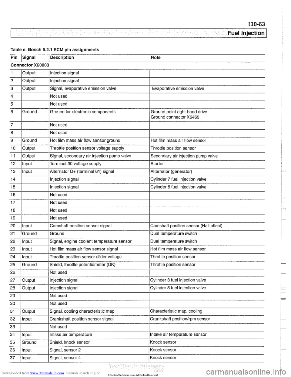
Table e. Bosch 5.2.1 ECM pin assignments
Pin
Isignal 1 Description 1 Note
Connector
X60003
1
2
3
4
5
6
7 8
9 10
11
12
13
14
15
16
17
18
19
20
21
ate alr empe
Output
Output
Output
Ground
Ground
Output
Output Input
Input
Input
Ground
22
23
24
25
26
27
28
29
30
Injection signal
Injection signal
Signal, evaporative emission valve
Not used
Not used
Ground for electronic components
Not used
Not used
Hot film mass air flow sensor ground
Throttle position sensor voltage supply
Signal, engine coolant temperature sensor
Hot
film mass air flow sensor signal
Throttle position sensor slider voltage
Shield, throttle potentiometer (DK) Not used
Injection signal
Injection signal
Not used
Not used
Input
Input
Input
Ground
Output
Output Evaporative emission
valve
Ground point right-hand drive
Ground connector
X6460
Hot film mass air flow sensor
Throttle position sensor
Signal, secondary air injection pump valve
Terminal
30 voltage supply
Alternator
D+ (terminal 61) signal
injection signal
Injection
signal
Not used
Not used
Not used
Not used
Camshaft position sensor signal
Ground Dual temperature switch
Hot film mass air flow sensor
Throttle position sensor
Throttle position sensor
Cylinder
8 fuel injection valve
Cylinder
5 fuel injection valve
Secondary air injection pump
valve
Starter
Alternator (generator)
Cylinder
7 fuel injection valve
Cylinder 6 fuel injection valve
Camshaft position sensor (Hall effect) Dual temperature
switch
Page 454 of 1002
Downloaded from www.Manualslib.com manuals search engine
-
Fuel Injection
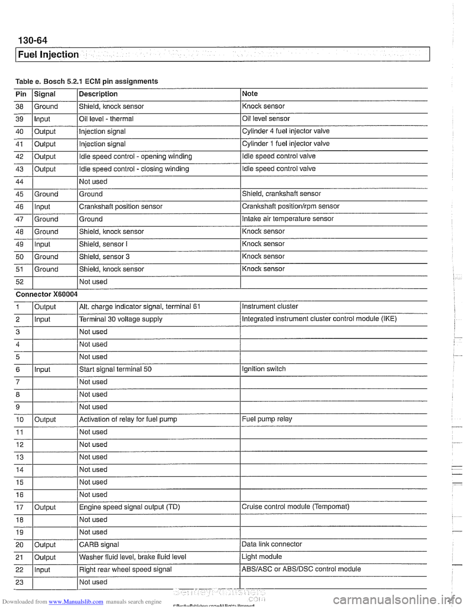
Table e. Bosch 5.2.1 ECM pin assignments
Pin
I~iqnal 1 Description 1 Note
I I I
46 llnput ICrankshaft position sensor Icrankshaft positionlrpm sensor
38
39
40
41
42
43
44
45 Ground Input
Output
Output
Output
Output
Ground
47
48
49
50
51
Not used
I Not used
52
Shield, knock sensor
Oil level
- thermal
Injection signal
injection signal
Idle speed control - opening winding
Idle speed control - closing winding
Not used
Ground
Ground
-- Ground Input
Ground
Ground Not used Knock sensor
Oil level sensor
Cylinder
4 fuel injector
valve
Cylinder
1 fuel injector valve
Idle speed control valve
Idle speed control valve
Shield, crankshaft sensor
5
6
7
12 Not used
Ground
Intake air temperature sensor
Connector
X60004
8
9 10
11
14 1 1 Not used I
Shield, knock sensor
Shield, sensor
I
Shield, sensor 3
Shield, itnock sensor
Input
- Knoclc sensor
Knock sensor
Knock sensor
Knock sensor
Instrument cluster
Output
2 llnput l~erminal 30 voltage supply /Megrated instrument cluster control module (IKE)
Alt. charge indicator signal, terminal 61 1
Not used
Start signal terminal
50
Not used
15
16
17
18
Output
Ignition switch
Not used
Not used
Activation of relay for fuel pump
Not used
19
Fuel pump relay
Output Not used
I I I 20 loutput ICARB signal /Data link connector
Not
used
Not used
Engine speed signal output (TD)
Not used
Light module
21
Cruise control module (Tempomat)
22 llnput I Right rear wheel speed signal /ABS/ASC or ABSIDSC control module
Oulput
Washer
fluid level,
brake fluid level
Page 461 of 1002
Downloaded from www.Manualslib.com manuals search engine
Fuel Injection I
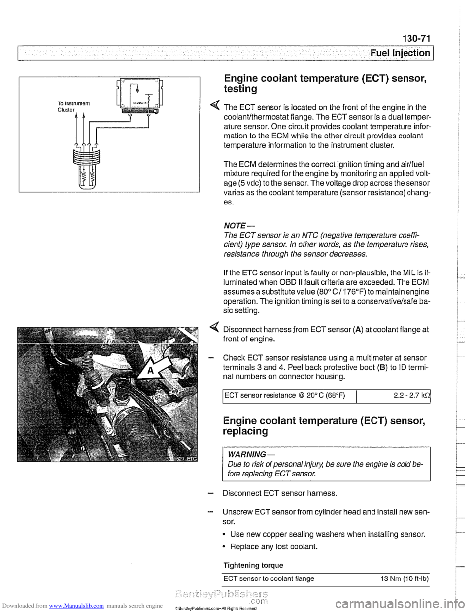
Engine coolant temperature (ECT) sensor,
testing
The ECT sensor is located on the front of the engine in the
coolant~thermostat flange. The ECT sensor is a dual temper-
ature sensor. One circuit provides coolant temperature infor-
mation to the ECM while the other circuit provides coolant
temperature information to the instrument cluster.
The ECM determines the correct ignition timing and
airlfuel
mixture required for the engine by monitoring an applied volt-
age
(5 vdc) to the sensor. Thevoltage drop across the sensor
varies as the coolant temperature (sensor resistance) chang-
es.
NOTE-
The ECT sensor is an NTC (negative temperature coeffi-
cient) type sensor. In other words, as the temperature rises,
resistance through the sensor decreases.
If the ETC sensor input is faulty or non-plausible, the MIL is il-
luminated when OBD
II fault criteria are exceeded. The ECM
assumes a substitute value
(80" C/ 176°F) to maintain engine
operation. The ignition timing is set to a
conse~ativelsafe ba-
sic setting.
Disconnect harness from
ECTsensor (A) at coolant flange at
front of engine.
- Check ECT sensor resistance using a multimeter at sensor
terminals
3 and 4. Peel back protective boot (B) to ID termi-
nal numbers on connector housing.
I ECT sensor resistance @ 20" C (68°F) I 2.2 - 2.7 lkCi
Engine coolant temperature (ECT) sensor,
replacing
I WARNING-
/ Due to risk ofpersonal injury, be sure the engine is cold be- I
I fore replacin~~~~sensor. -
-
I
- Disconnect ECT sensor harness.
- Unscrew ECT sensor from cylinder head and install new sen-
sor.
Use new copper sealing washers when installing sensor.
Replace any lost coolant.
Tightening torque
ECT sensor to coolant flange 13 Nm (10 it-lb)
Page 463 of 1002
Downloaded from www.Manualslib.com manuals search engine
( Mass Air Flow Sensor
1" Intake air temp. (NTC)
Sensor qround
Reference voltage . . . -., f fitr mass signal I
Fuel Injection I
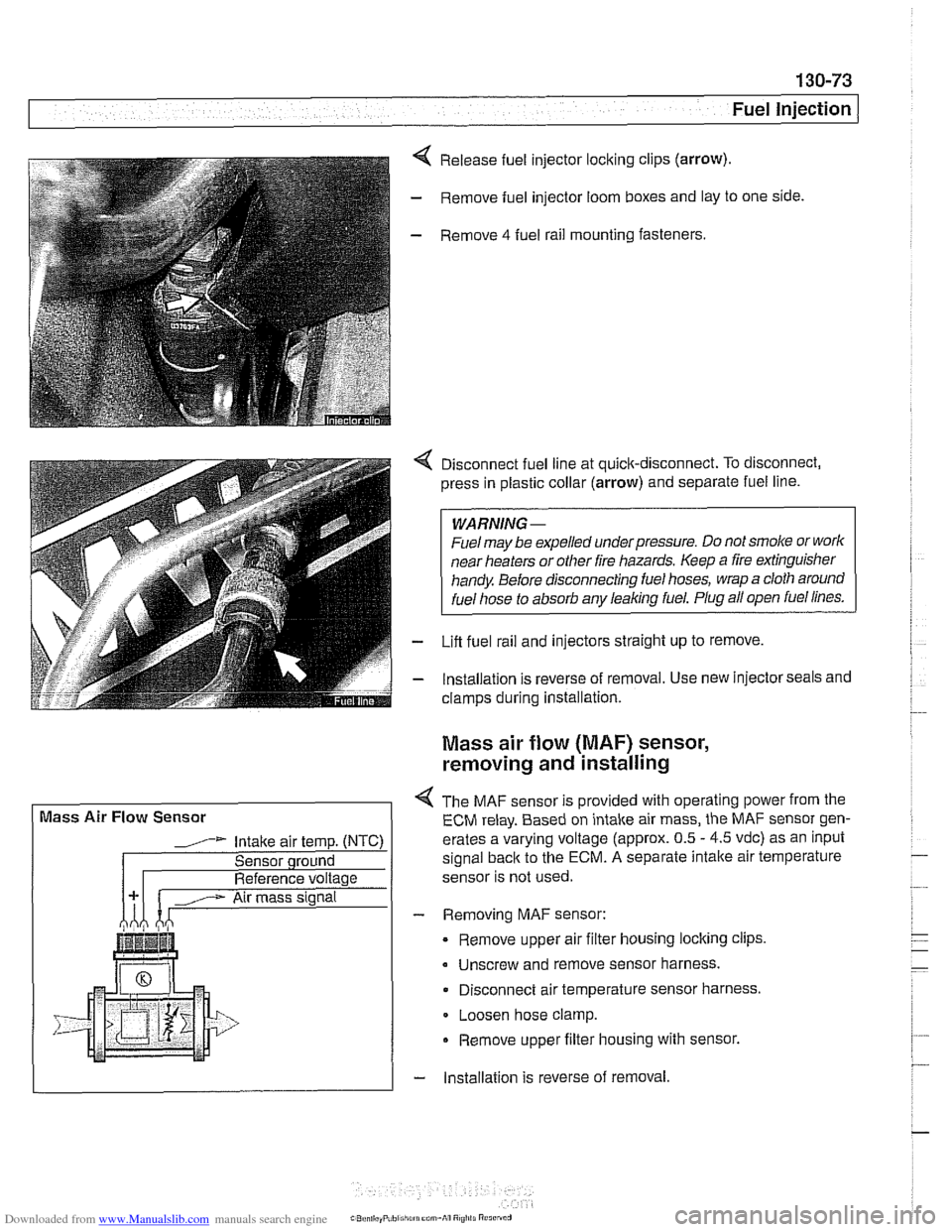
Release fuel injector locking clips (arrow).
- Remove fuel injector loom boxes and lay to one side.
- Remove 4 fuel rail mounting fasteners.
4 Disconnect fuel line at quick-disconnect. To disconnect,
press in plastic collar (arrow) and separate fuel line.
WARNING -
Fuel may be expelled underpressure. Do not srnol(e or work
near heaters or
other fire hazards. Keep a fire extinguisher
handy. Before disconnecting fuel hoses, wrap a cloth around
fuel hose
to absorb anv leakinq fuel. Plug all open fuel lines.
- Lifl fuel rail and injectors straight up to remove.
- lnstallation is reverse of removal. Use new injector seals and
clamps during installation.
Mass air flow (MAF) sensor,
removing and installing
4 The MAF sensor is provided with operating power from the
ECM relay. Based on intake air mass, the MAF sensor gen-
erates a varying voltage (approx. 0.5
- 4.5 vdc) as an input
signal
back to the ECM. A separate intalte air temperature
sensor is not used.
- Removing MAF sensor:
Remove upper air filter housing locking clips
Unscrew and remove sensor harness.
Disconnect air temperature sensor harness.
Loosen hose clamp.
Remove upper filter housing with sensor.
- lnstallation is reverse of removal
Page 465 of 1002
Downloaded from www.Manualslib.com manuals search engine
130-75
Fuel Injection
Secondary air injection, overview
The secondary air system pumps ambient air into the exhaust
stream afteracoid engine start to reduce the warm-up time of
the catalytic converters and to reduces HC and CO emis-
sions. The ME
7.2 ECM controls and monitors the secondary
air injection system. The secondary air pump operates at a
starttemperature of between 10°C
(50°F) and 40°C (104°F).
and continues to operate for a maximum of
2 minutes at idle
speed.
The electric air pump draws in ambient air and supplies it to
the
checlc valve. The vacuum vent valve (solenoid) switches
vacuum to open the
checlc valve when activated by the ECM.
Once opened, the checlc
valve allows air to be pumped into
the exhaust stream.
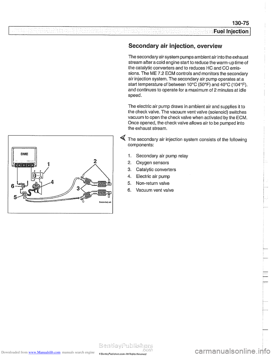
4 The secondary air injection system consists of the following
components:
1. Secondary air pump relay
2. Oxygen sensors
3. Catalytic converters
4. Electric air pump
5. Non-return valve
6. Vacuum vent valve
Page 469 of 1002
Downloaded from www.Manualslib.com manuals search engine
Fuel Injection I
Connector X60004 (continued)
8 10
11
12
13
14
15
16
9
Output 0
Input
17
18
19
20
21
22
23
24
25
26
27
28
29
30
31
32
33
34
35
36
39
llnput lsignal l~oolant outlet temperature sensor
Output
Output
Ground
Input
Output
I I - I
40 /output Istart signal Istarter relay
Pedal position sensor (PWG), signal
Output Input
Output
input
Input
Input
Input
Input
Input
input
Input
Output
Input/-output
Input/-output
37
Connector X60003
Pedal position sensor
Fuel pump relay, activation
Oil pressure indicator Pedal position sensor (PWG), ground
Pedal position sensor (PWG), signal
Pedal position sensor (PWG), power supply
Not used
Not used Fuel
pump relay
Instrument cluster
Pedal position sensor
Pedal position sensor
Pedal position sensor
Engine speed signal output (TD)
Not used
Signal
back-up light
DM-TL (diagnostic module,
tank leakage)
Signal oil level sensor
Right rear wheel speed, signal
Clutch pedal position switch, signal
Brake light switch, signal
Not used
Voltage supply, terminal
15
Data link, MFL (multi-function steering wheel)
Brake light test signal
AJC compressor signal
DM-TL (diagnostic module, tank
leakage)
Not used
Diagnosis signal
TxD
Communication link (EWS)
Not used
Not used
CAN-BUS hiqh
38 1 Ground l~round I Coolant outlet temperature sensor
OED II plug
Integrated instrument cluster control module (IKE)
Light module
ABSIDSC control module
Clutch pedal position switch
Brake light switch
Fuse
F14
Airbag contact coil spring
Brake light switch
Heating and
A/C control module
OBD
II plug
Electronic immobilizer (EWS)
CAN-Bus link
CAN-Bus link
Input/-output CAN-Bus low
Page 474 of 1002
Downloaded from www.Manualslib.com manuals search engine
Fuel Tank and Fuel Pump
Evaporative system troubleshooting
- Start by accessing diagnostic trouble codes (DTCs) using a
BMW or BMW compatible aftermarket scan tool.
For purposes of OBD
II emissions compliance, the DME
system sets a diagnostic trouble code (DTC) when it de-
tects a leak that is equal or larger than minimum
lealc
sensed by system.
Malfunction Indicator Light (MIL) is illuminated upon sec-
ond recurrence of fault. See OBD On-Board Diagnostics.
- When leak testing, observe following conditions to obtain
plausible results:
Fuel tank
'1, to 'I., full.
0 Vehicle parked for at least 2 hours to allow fuel to reach
room temperature.
Ideal fuel temperature is 10"- 20°C
(50"
- 68" F).
Do not refuel immediately before
lealc test.
- If a leak is detected, check the following areas:
* Fuel filter cap (leaking or off).
Fuel tank ventilation lines leaking at fuel
tank or activated
carbon canister.
i
Tank ventilation valve leaking (in engine compartment).
Fuel level
sensorlfuel pump cap leaking.
Evaporative system component replacement is covered later
in
th~s group in Fuel Tank and Fuel Lines.
Page 520 of 1002
Downloaded from www.Manualslib.com manuals search engine
--
Radiator and Cooling System 1
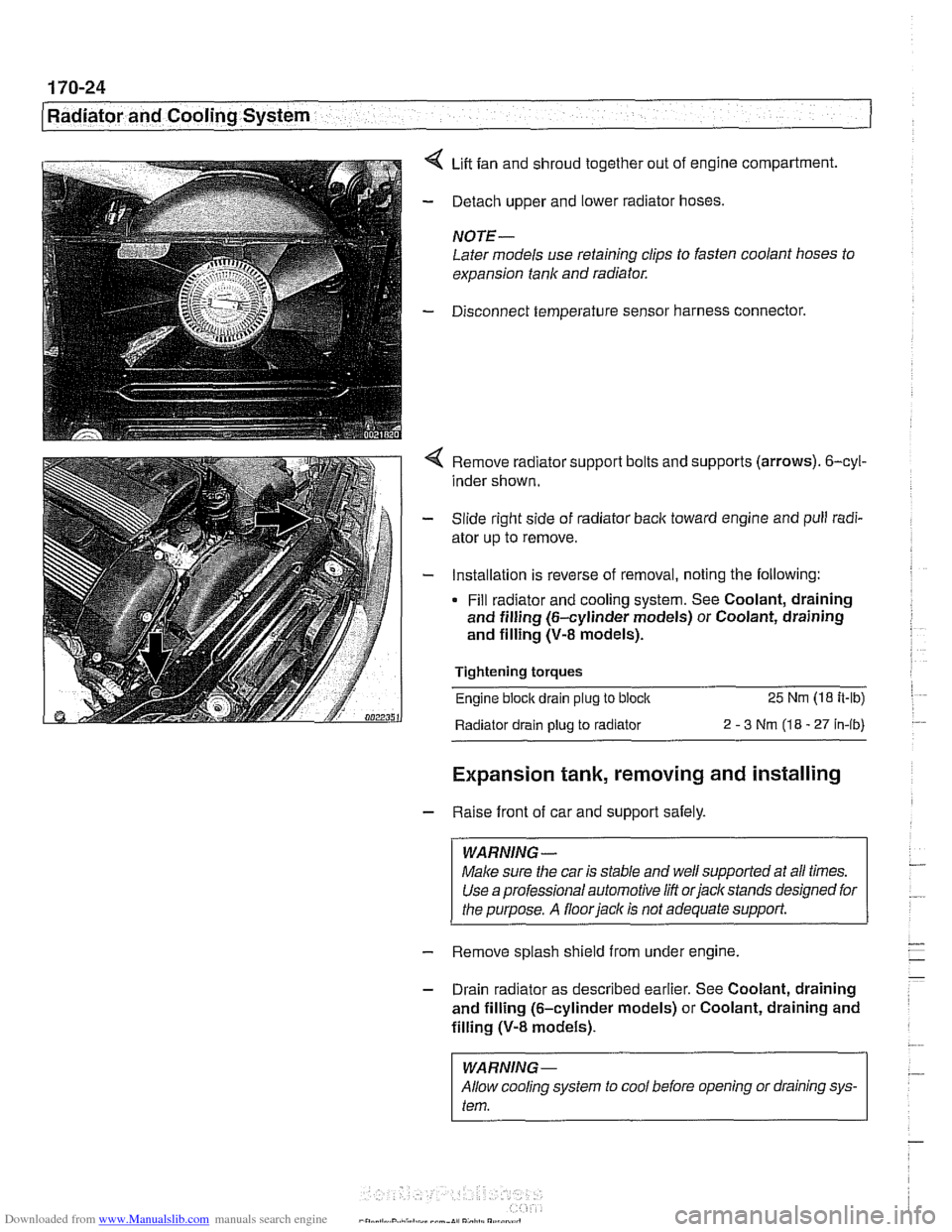
4 Lift fan and shroud together out of engine compartment.
- Detach upper and lower radiator hoses.
NOTE -
Later models use retaining clips to fasten coolant hoses to
expansion tank and radiator.
- Disconnect temperature sensor harness connector.
4 Remove radiator support bolts and supports (arrows). 6-cyl-
inder shown.
- Slide right side of radiator back toward engine and pull radi-
ator up to remove.
- Installation is reverse of removal, noting the following:
Fill radiator and cooling system. See Coolant, draining
and filling (6-cylinder models) or Coolant, draining
and filling (V-8 models).
Tightening torques
Engine block drain
plug to block 25 Nm (18 it-lb)
Radiator drain plug
to radiator 2 - 3 Nm (18 - 27 in-ib)
Expansion tank, removing and installing
- Raise front of car and support safely.
WARNING -
Make sure the car is stable and well supported at all times.
Use a professional automotive
/iff orjacltstands designed for
the purpose. A
floorjacl~ is not adequate support.
- Remove splash shield from under engine.
- Drain radiator as described earlier. See Coolant, draining
and filling (6-cylinder models) or Coolant, draining and
filling
(V-8 models).
I WARNING-
Allow cooling system to cool before opening or draining sys-
I tem.
Page 524 of 1002
Downloaded from www.Manualslib.com manuals search engine
180-2
Exhaust System
The exhaust system is designed to be maintenance free, al-
though regular inspection is warranted due to the harsh oper-
ating conditions. Under normal conditions, the catalytic
converter does not require replacement unless it is damaged.
New fasteners, clamps, rubber mounts and gaskets should
be used when replacing exhaust components.
A liberal appli-
cation of penetrating oil to the exhaust system nuts and bolts
in advance may make removal easier.
WARNING -
The exhaust system and catalytic converter operate at
very high temperatures. Allow components to cool before
servicing. Wear protective clothing to prevent burns.
Do not use flammable chemicals near a hot
cataiyiic
converter.
Corroded exhaust system components crumble easily
and often have exposed sharp edges. To avoid injury,
wear eye protection and heavy gloves when working
Exhaust system, removing and installing
The removal and installation procedures given here are gen-
eral procedures for all models. The removal of the exhaust
system as a complete unit is recommended. Once the com-
plete system is removed from the car, individual pipes and
mufflers can be more easily replaced.
WARNING-
Exhaust gases are colorless, odorless, and very toxic. Run
the engine only in a well-ventilated area. Immediately repair
any
leaks in the exhaust system or structural damage to the
car body that
might allow exhaust gases to enter the passen-
ger compartment.
CAUTION-
Use care not to drag or bang oxygen sensors. Oxygen sen-
sors can be easily ruined.