Temperature sensor BMW 528i 1997 E39 Service Manual
[x] Cancel search | Manufacturer: BMW, Model Year: 1997, Model line: 528i, Model: BMW 528i 1997 E39Pages: 1002
Page 727 of 1002
Downloaded from www.Manualslib.com manuals search engine
Rear Suspension
- Remainder of installation is reverse of removal, noting the fol-
lowing.
Tighten suspension arm and shock absorber fasteners to
final torque only afler vehicle has been lowered and sus-
pension has settled.
Tightening torques
ABS pulse sensor to wheel bearing carrier 8
Nrn (6 ft-lb)
Air line connection 2 Nrn (18 in-lb)
Brake rotor to hub 16
Nrn (12 ft-lb)
Driveshaft
CV joint to final drive flange
- MI0 (Torx bolts) 70
Nrn (51 ft-lb)
- MB (compression nut) 32 Nrn (24 ft-lb)
Rear
brake pad carrier (caliper) to wheel 65
Nrn (48 ft-lb)
bearing carrier
Road wheel to hub
120ilO Nrn
(89 i-7 ft-lb)
Rear subframe mounting bushings,
removing and installing
- Remove rear subframe mounting bolts as described earlier.
Lower
subframe approximately 40 - 45 mm (1 -2 in).
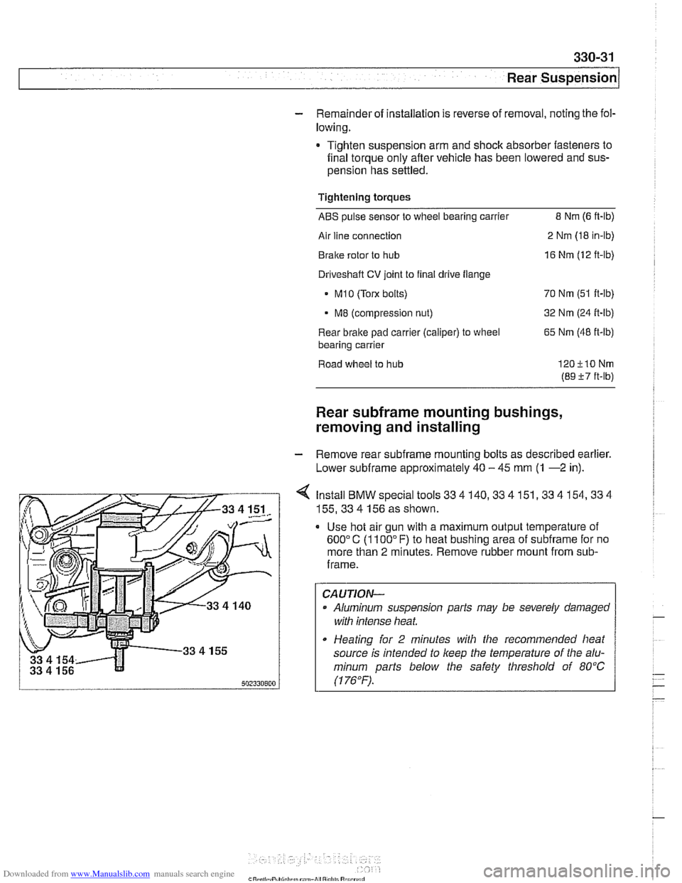
4 Install BMW special tools 33 4 140,33 4 151,33 4 154,33 4
155,33 4 156 as shown.
Use hot air gun with a maximum output temperature of
600°C (1100" F) to heat bushing area of subframe for no
more than
2 minutes. Remove rubber mount from sub-
frame.
CAUTION-
Aluminum suspension parts may be severely damaged
witli intense heat
* Heating for 2 minutes with the recommended heat
source is intended to
keep the temperature of the alu-
minum
parts below the safety threshold of 80°C
(1 76°F). .
Page 966 of 1002
Downloaded from www.Manualslib.com manuals search engine
OBD-6
On-Board Diagnostics
Fuel system monitoring. This monitor looks at the fuel
delivery needed (long
/short term fuel trim) for proper engine
operation based on programmed data. If too much or not
enough fuel is delivered over a predetermined time, a DTC is
set and the MIL illuminates.
Fuel trim refers to adiustments to base fuel schedule.
Lono- ., term fuel trim refers to gradual adjustments to the fuel
calibration adjustment as compared to short term fuel trim.
Long term fuel trim adjustments compensate for gradual
changes that occur over time.
Fuel system monitoring monitors the calculated injection time
(ti) in relation to enginespeed, load and precatalyticconverter
oxygen
sensor(s) signals.
Using this data, the system optimizes fuel delivery for all
engine operating conditions.
Evaporative system monitoring. This monitor checks the
the fuel storage system and related fuel lines for leaks. It can
detect very small leaks anywhere in the system.
A leak detection unit (LDP or DMTL) is used to pressurize the
evaporative control system on a continuous basis (as the
drive cycle allows) and to
check system integrity.
Drive cycle
The OED II drive cycle is an important concept in
understanding OBD
II requirements. The purpose of the drive
cycle is to run ail of the emission-related on-board diagnostics
over a broad range of driving conditions.
A drive cycle is considered complete when all of the
diagnostic monitors have run their tests without interruption.
~ora drive cycle to be initiated, the vehicle must be started
cold and brought up to
1 60°F and at least 40°F above its
original starting temperature.
Readiness codes
Inspection/maintenance (I/M) readiness codes are mandated
as part of OBD
II. The readiness code is stored aftercomplete
diagnostic monitoring of specified components and systems
is carried out. The readiness code function was designed to
prevent manipulating an
I/M emission test procedure by
clearing faults codes or disconnecting the ECM or battery.
Page 973 of 1002
Downloaded from www.Manualslib.com manuals search engine
On-Board Diagnostics
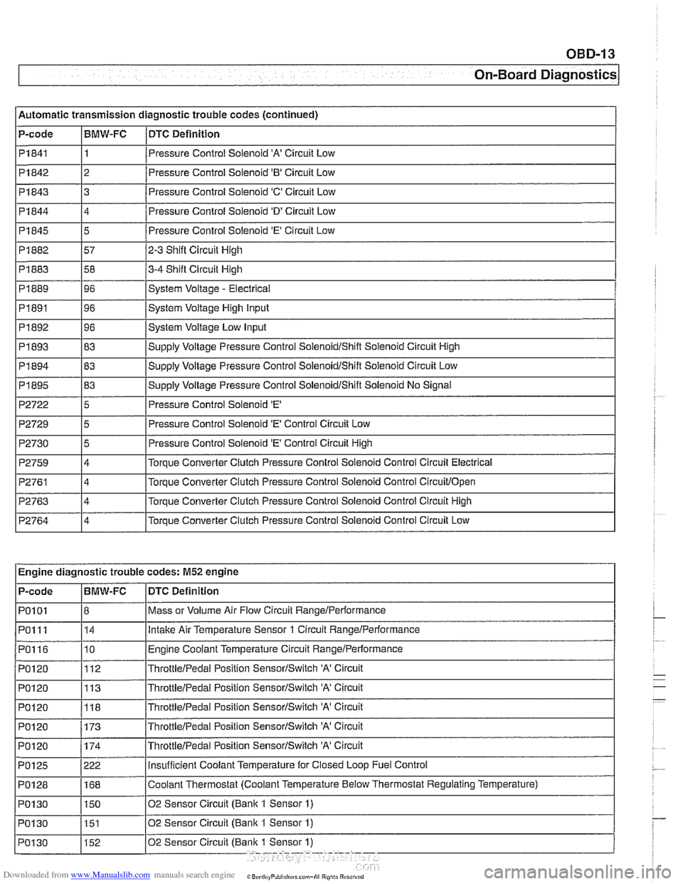
l~utomatic transmission diagnostic trouble codes (continued)
P-code
1 Pi844
I I
14 /Pressure Control Solenoid 'D' Circuit Low
I I PI841 11 /Pressure Control Solenoid 'A' Circuit Low
BMW-FC
Pi842
I
P2722 15 I Pressure Control Solenoid 'E' I
DTC
Definition
Pi 845
Pi 882
Pi 883
PI 889
PI891
PI 892
PI 893
Pi 843 3 8
2 Pressure Control Solenoid '0' Circuit Low
5
57
58
96
96
96
83
P2729
P2730
P2759
P2761
P2763
P2764
Pressure Control Solenoid 'E' Circuit Low
2-3 Shift Circuit High
3-4 Shift Circuit High
System Voltage
- Electrical
System Voltage High Input
System Voltage Low Input
SUDP~V Voltaqe Pressure Control SoienoidIShift Solenoid Circuit High
~~ ~~ ~ Engine diagnostic trouble codes: M52 engine
5
5
4
4
4
4
I I
Pressure Control Solenoid 'E' Control Circuit Low
Pressure Control Solenoid
'E' Control Circuit High
Torque Converter Clutch Pressure Control
Solenoid Control Circuit Electrical
Torque Converter Clutch Pressure Control Solenoid Control
Circuitlopen
Torque Converter Clutch Pressure Control Solenoid Control Circuit High
Torque Converter Clutch Pressure Control Solenoid Control Circuit Low
DTC Definition
Mass or Volume Air
Flow Circuit RangeIPerformance
lntalte Air Temperature Sensor 1 Circuit Rangelperformance
Engine Coolant Temperature Circuit RangeIPerformance
ThrottieIPedai Position SensorISwitch 'A' Circuit
ThrottleIPedai Position SensorISwitch 'A' Circuit
P-code
PO1
01
PO1 11
PO116
PO120
PO120
PO1 20 BMW-FC
8 14
10
112
113
POI 20 1173 /~hrottie/~edal Position SensorISwitch 'A' Circuit
118
ThrottieIPedai Position SensorISwitch 'A' Circuit
Page 975 of 1002
Downloaded from www.Manualslib.com manuals search engine
OBD-15
On-Board ~iagnosticsl
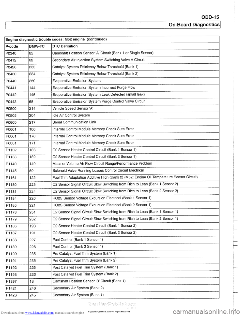
Engine diagnostic trouble codes: M52 engine (continued)
P-code
PO340
PO412
PO420
PO430
PO440
PO441
PO442
PO443
PO500
PO505
PO600
PO601
PO601
I PO601
~1132
~1133
BMW-FC
65
62
233
234
250 144
-
145
68
214
i I
DTC Definition
Camshalt Position Sensor 'A' Circuit (Bank 1 or Single Sensor)
Secondary Air Injection System Switching Valve A Circuit
Catalyst System Efficiency Below Threshold
(Bank 1)
Catalyst System Efficiency Below Threshold (Bank 2)
Evaporative Emission System
Eva~orative Emission Svstem Incorrect Purge Flow .
Evaporative Emission System Leak Detected (small leak)
Evaporative Emission System Purge Control Valve Circuit
Vehicle Speed Sensor 'A'
204
21 7
100
170
171
188
189
PI161
PI180
PI181
PI184
PI185
PI178
02 Sensor Heater Control Circuit (Bank 2 Sensor 2) I
idle Air Control System
Serial Communication
Link
Internal Control Module Memory Check Sum Error
Internal Control Module Memory
Check Sum Error
Internal Control Module Memory
Check Sum Error
02 Sensor Heater Control Circuit (Bank 1 Sensor
1)
02 Sensor Heater Control Circuit (Bank 2 Sensor 1)
Mass or Volume Air Flow Circuit RangeIPerlormance Problem PI140
I
I I
P1188 1227 I Fuel Control (Bank 1 Sensor 1)
PI145 150 /Solenoid Valve Running Losses Control Circuit Electrical
149
122
223
224
220 221
231
I I
P1189 1228 I Fuel Control (Banlc 2 Sensor 1)
Fuel Trim Adaptation Additive High (Bank 2) (M52: Engine Oil Temperature Sensor Circuit)
02 Sensor Signal Circuit Slow Switching from Rich to Lean
(Bank 1 Sensor 2)
02 Sensor Signal Circuit Slow Switching from Rich to Lean
(Bank 2 Sensor 2)
H02S Sensor Voltage Excursion Electrical (Banlc 1 Sensor 1)
HO2S Sensor Voltage Excursion Electrical (Banlc 2 Sensor 1)
02 Sensor Sianai Circuit Slow Switchina from Rich to Lean (Bank 1 Sensor 1)
02 Sensor Signal Circuit Slow Switching from Rich to Lean (Bank 2 Sensor 1) PI179
I I
PI190 1235 I Pre Catalyst Fuel Trim System (Banlc 1)
PI186 1190 102 Sensor Heater Control Circuit (Banlc 1 Sensor 2)
232
I I
PI191 1236 I Pre
Catalyst Fuel Trim System (Banlc 2)
PI192
. . -- - i Pi193 1226 I Post Catalvst Fuel Trim Svstem (Bank 2)
225
PI397
I I
Post Catalyst Fuel Trim System (Bank 1)
PI421 1246 /Secondarv Air System (Bank 2)
18
Secondary Air System (Bank
1) PI423
Camshaft Position Sensor '0' Circuit (Bank 1)
I 245
Page 976 of 1002
Downloaded from www.Manualslib.com manuals search engine
--- -
On-Board Diagnostics - - --- - -- - -
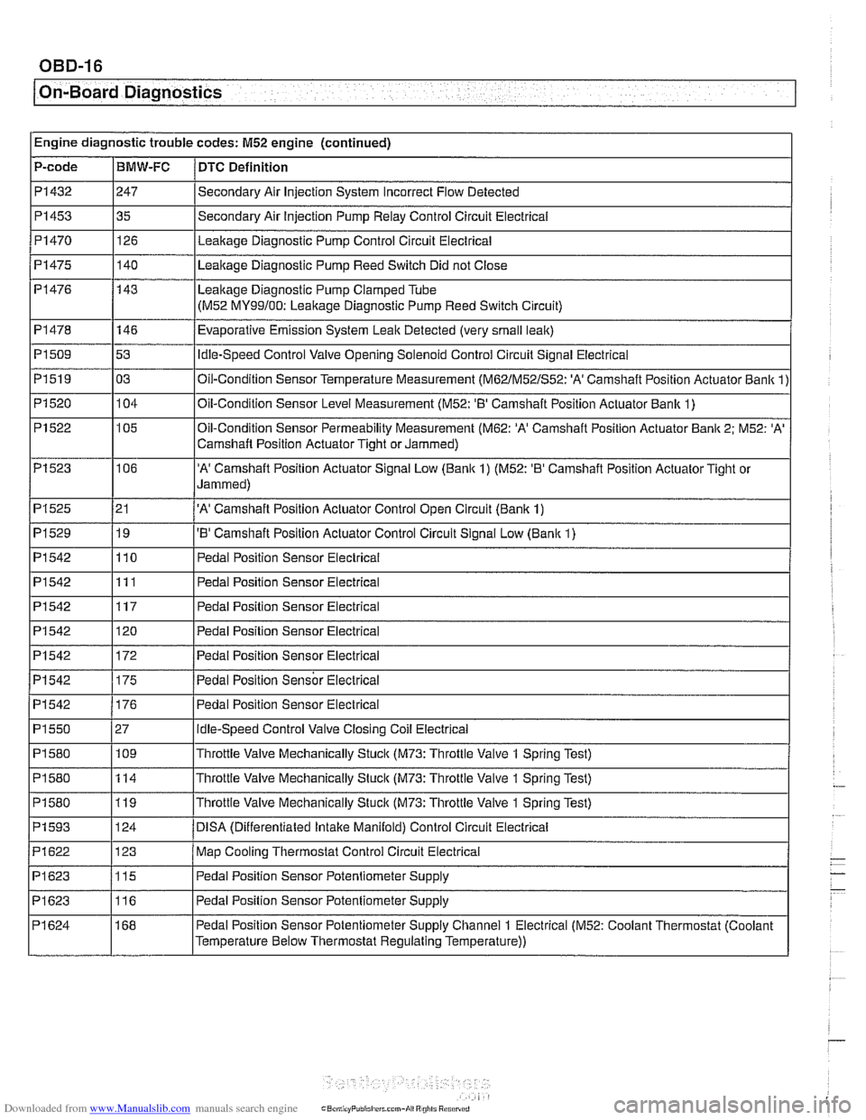
PI542
PI550
PI580
PI 580
PI 580
PI 593
PI622
PI623
PI623
PI 624 176
27 109
114
119
124
123
115
116
168 Pedal Position Sensor Electrical
Idle-Speed
Control Valve Closing Coil Electrical
Throttle Valve Mechanically Stuck
(M73: Throttle Valve 1 Spring Test)
Throttle Valve Mechanically Stuck
(M73: Throttle Valve 1 Spring Test)
Throttle Valve Mechanically Stuck
(M73: Throttle Valve 1 Spring Test)
DlSA (Differentiated lntalte Manifold) Control Circuit Electrical
Map Cooling Thermostat Control Circuit Electrical
Pedal Position Sensor Potentiometer Supply
Pedal Position Sensor Potentiometer Supply
Pedal Position Sensor Potentiometer Supply Channel
1 Electrical (M52: Coolant Thermostat (Coolant
Temperature Below Thermostat Regulating Temperature))
Page 977 of 1002
Downloaded from www.Manualslib.com manuals search engine
On-Board ~iaanosticsl
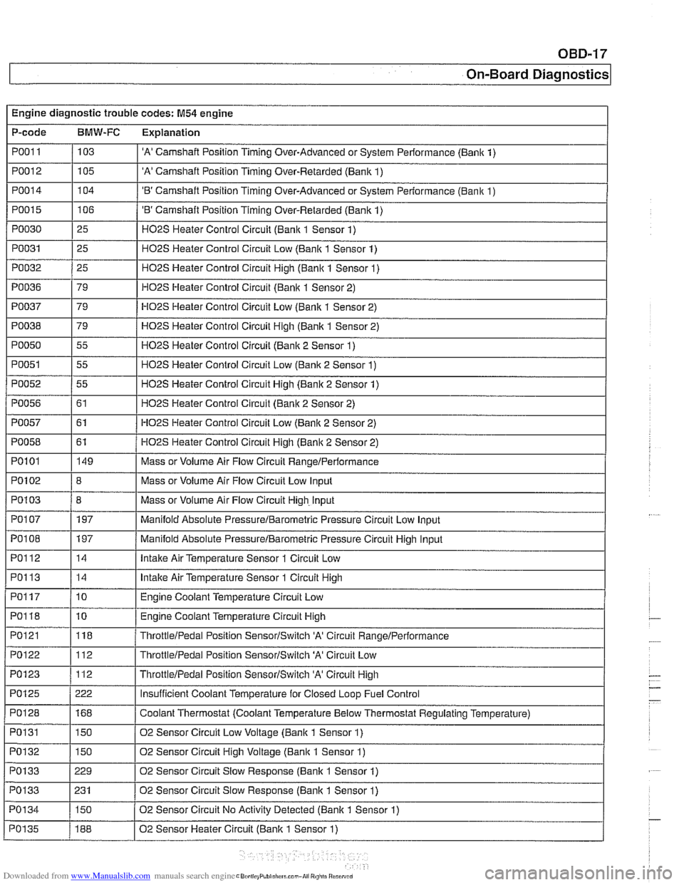
Engine diagnostic trouble codes: M54 engine
P-code
BMW-FC Explanation
PO01 I / 103 I 'A' Camshaft Position Timing Over-Advanced or System Performance (Banlc 1) I I
PO012 1105 I 'A' Camshaft Position Timing Over-Retarded (Bank 1) I I
PO01 4 1104 I 'B' Camshaft Position Timing Over-Advanced or System Performance (Bank 1)
PO01 5
PO030
PO031
PO032
I 1
PO038 179 / HO2S Heater Control Circuit High (Bank 1 Sensor 2)
I I -.
I I
PO050 1 55 I H02S Heater Control Circuit (Bank 2 Sensor 1)
106
25
25
25
PO036
I I
PO051 1 55 I H02S Heater Control Circuit Low (Bank 2 Sensor 1)
'B' Camshaft Position Timing Over-Retarded (Bank 1)
H02S Heater Control Circuit (Bank 1 Sensor 1)
H02S Heater Control Circuit Low (Bank 1 Sensor 1)
H02S Heater Control Circuit Hiqh (Bank 1 Sensor 1)
PO037 1 79 I HO2S Heater Control Circuit Low (Bank 1 Sensor 2)
79
HOPS Heater
Control Circuit (Banlc 1 Sensor 2)
PO052
PO056
PO057
PO058
I I
PO1 03 / 8 I Mass or Volume Air Flow Circuit High. Input
I I -.
I I
PO1 07 1 197 I Manifold Absolute PressureIBarometric Pressure Circuit Low Input
55
61
61
61
PO101
I I
POI08 1197 / Manifold Absolute PressureIBarometric Pressure Circuit High Input
H02S Heater Control Circuit High (Bank 2 Sensor 1)
H02S Heater Control Circuit (Bank 2 Sensor 2)
HO2S Heater Control Circuit Low (Bank 2 Sensor 2)
HO2S Heater Control Circuit Hiqh (Banlc 2 Sensor 2)
PO102 18 I Mass or Volume Air Flow Circuit Low Input
149
I I -
PO122 112 ThrottleIPedai Position SensorISwitch 'A' Circuit Low
PO123 1112 I ThrottleIPedal Position SensorISwitch 'A' Circuit High
Mass
or Volume Air Flow Circuit
RangeIPerformance
PO112
PO113
PO1 17
PO118
PO121
14
14
10
10
118
PO128
PO1 31
PO132
PO133
PO133
PO1 34 Intake
Air Temperature Sensor 1 Circuit Low
Intake Air Temperature Sensor 1 Circuit High
Engine Coolant Temperature Circuit Low
Engine Coolant Temperature Circuit High
ThrottleIPedal Position SensorISwitch 'A' Circuit RanqeIPerformance
I I
168
150
150
229
231
150
PO135
Coolant Thermostat (Coolant Temperature Below Thermostat Regulating Temperature)
02 Sensor Circuit Low Voltage (Bank 1 Sensor 1)
02 Sensor Circuit High Voltage (Bank 1 Sensor 1)
02 Sensor Circuit Slow Response (Bank
1 Sensor 1)
02 Sensor Circuit Slow Response
(Banlc 1 Sensor 1)
02 Sensor Circuit No Activitv Detected
(Banlc 1 Sensor 1)
188 02 Sensor Heater Circuit (Bank 1 Sensor 1)
Page 980 of 1002
Downloaded from www.Manualslib.com manuals search engine
I On-Board Diagnostics
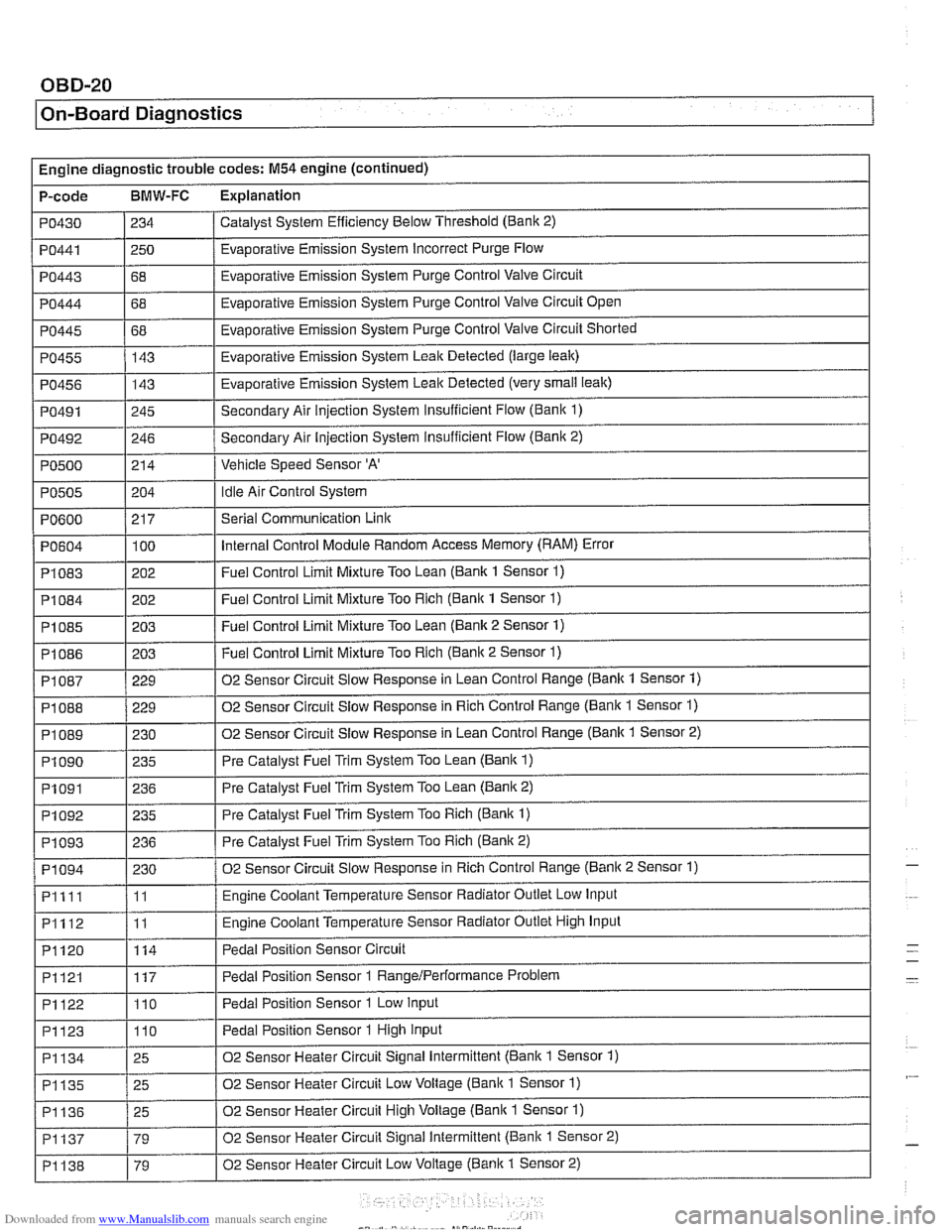
Engine diagnostic trouble codes: M54 engine (continued)
P-code
BMW-FC Explanation
Catalyst System Efficiency Below Threshold (Bank 2)
PO430
PO443
PO444
PO445
PO455
PO456
PO491
PO492
PO500
PO441 1250 / Evaporative Emission System Incorrect Purge Flow
234
I I
68
68
68 143
143
245
246
214
PO604
PI083
PI084
PI085
PI086
Evaporative Emission System Purge Control Valve Circuit
Evaporative Emission System Purge Control Valve Circuit Open
Evaporative Emission System Purge Control Valve Circuit Shorted
Evaporative Emission System Leak Detected (large leak)
Evaporative Emission System Leak Detected (very
small leak)
Secondary Air injection System Insufficient Flow (Bani( 1)
Secondary Air Injection System insufficient Flow
(Banic 2)
Vehicle Speed Sensor
'A'
Idle Air Control System PO505
.
PI 087
PI 088
PI089
PI090
PO600 / 217 I Serial Communication Link
204
100
202
202
203
203
PI091
PI092
PI093
PI094
Pllll
PI112
PI120
Internal Control Module Random Access Memory (RAM) Error
Fuel Control Limit Mixture Too Lean (Bank 1 Sensor
1)
Fuel Control Limit Mixture Too Rich (Bank 1 Sensor 1)
Fuel Control Limit Mixture Too Lean (Bank 2 Sensor 1)
Fuel Control Limit Mixture Too Rich (Banic 2 Sensor 1) ~ ~
229
229
230 235
PI121
PI122
PI123
02 Sensor Circuit Slow Response in Lean Control Range (Bank 1 Sensor 1)
02 Sensor Circuit Slow Response in Rich Control Range (Bank 1 Sensor
1)
02 Sensor Circuit Slow Response in Lean Control Range (Banlc 1 Sensor 2)
Pre Catalyst Fuel Trim System Too Lean
(Bank 1)
236
235
236
230
11
11
114
PI134
PI135
PI136
PI137
PI138
Pre Catalyst Fuel Trim System Too Lean (Banic 2)
Pre Catalyst Fuel Trim System Too Rich
(Bank 1)
Pre Catalyst Fuel Trim System Too Rich (Bank 2)
02 Sensor Circuit Slow Response in Rich Control Range (Banic 2 Sensor 1)
Engine Coolant Temperature Sensor Radiator Outlet Low Input
Engine Coolant Temperature Sensor Radiator Outlet High Input
Pedal Position Sensor Circuit
117
110
110
25
25
25
79
79 Pedal Position Sensor 1
RangeIPerformance Problem
Pedal Position Sensor 1 Low Input
Pedal Position Sensor 1 High Input
02 Sensor Heater Circuit Signal Intermittent (Bank 1 Sensor 1)
02 Sensor Heater Circuit Low Voltage (Bank 1 Sensor
1)
02 Sensor Heater Circuit High Voltage (Bank 1 Sensor 1)
02 Sensor Heater Circuit Signal Intermittent (Bank 1 Sensor 2)
02 Sensor Heater Circuit Low Voltage
(Banic 1 Sensor 2)
-
-
Page 983 of 1002
![BMW 528i 1997 E39 Service Manual Downloaded from www.Manualslib.com manuals search engine
OBD-23
On-Board ~iagnostics]
I I
PI625 / 147 I Pedal Position Sensor Potentiometer Supply Channel 2 Electrical 1
Engine diagnostic troubl BMW 528i 1997 E39 Service Manual Downloaded from www.Manualslib.com manuals search engine
OBD-23
On-Board ~iagnostics]
I I
PI625 / 147 I Pedal Position Sensor Potentiometer Supply Channel 2 Electrical 1
Engine diagnostic troubl](/img/1/2822/w960_2822-982.png)
Downloaded from www.Manualslib.com manuals search engine
OBD-23
On-Board ~iagnostics]
I I
PI625 / 147 I Pedal Position Sensor Potentiometer Supply Channel 2 Electrical 1
Engine diagnostic trouble codes: M54 engine (continued)
P-code
BMW-FC Explanation
PI 604
PI604
PI619
PI620
PI624
PI632
PI633
PI634
P1 634
PI 634
PI 635
PI 636 50
51 123
123
146 i I
I
I Barometric Pressure Circuit Low
Control
Module Self-Test,
Speed Monitoring
Control Module Self-Test, Speed Monitoring
Map Cooling Thermostat Control Circuit Signal Low
Map Cooling Thermostat Control Circuit Signal High Pedal Position Sensor Potentiometer Supply Channel
1 Electrical (M52: Coolant Thermostat (Coolant
Temperature Below Thermostat Regulating Temperature))
115
115
115
135
136
115
109
PI639
PI675
PI694
P2088
P2089
P2090
P2091
I I
P2229 1197 I Barometric Pressure Circuit High
Throttle
Valve Adaptation Conditions Not Met
Throttle
Valve Adaptation Limp-Home Position Unknown
Throttle Valve Adaptation Spring Test Failed
Throttle
Valve Adaptation Spring Test Failed
Throttle
Valve Adaptation Spring Test Failed
Throttle Valve Adaptation Lower Mechanical Stop not Adapted
Throttle Valve Control Circuit
Throttle Valve Position Control, Control Deviation
PI 637
I I
P2270 1215 1 02 Sensor Signal Stuck Lean (Banic 1 Sensor 2)
PI 638 1160 I Throttle Valve Position Control Throttle Stucic Temporarily
162
161
135
136
21
21 19
19 Throttle
Valve Position Control Throttle
Stucic Permanently
Throttle Valve Actuator Start Test Re-Adaptation Required
Throttle Valve Actuator Start Test Spring Test and Limp-Home Position Failed
'A' Camshaft Position Actuator Control Circuit Low (Banlc 1)
'A' Camshaft Position Actuator Control Circuit High (Banlc 1)
'B' Camshaft Position Actuator Control Circuit Low (Bank 1)
'B' Camshaft Position Actuator Control Circuit High (Bank 1)
P2271
P2272
P2273
P3041
P3198 I I -
215
216
21 6
10481
10205 02
Sensor Signal Stucic Lean (Bank 1 Sensor 2)
02 Sensor Signal
Stuclc Lean (Bank 2 Sensor 2)
02 Sensor Signal Stuclc Lean (Bank 2 Sensor 2)
02 Sensor Lean and Rich Voltage Thresholds not Reached (Bank 2 Sensor 2)
Engine Coolant Temperature Gradient Too High
Engine Coolant Temperature Signal Stuck
P3199
P3238 1 10289 I Control Module Monitoring TPU Chip Defective
10207
Page 984 of 1002
Downloaded from www.Manualslib.com manuals search engine
/ On-Board Diaanostics I
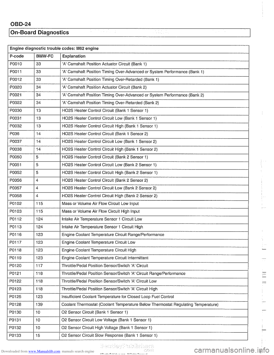
Engine diagnostic trouble codes: M62 engine
P-code
PO01 1
PO012
PO020
PO021
PO022
PO030
PO031
PO032
I I
PO038 / 14 I H02S Heater Control Circuit High (Bank 1 Sensor 2)
PO010 / 33 / 'A' Camshaft Position Actuator Circuit (Bank 1)
BMW-FC
I I -.
Explanation
33
33
34
34
34 13
13
13
PO36
'A' Camshaft Position Timing Over-Advanced or System Performance (Bank 1)
'A' Camshaft Position Timing Over-Retarded (Bank 1)
'A' Camshaft Position Actuator Circuit (Bank 2)
'A' Camshaft Position Timing Over-Advanced or System Performance (Banlc 2)
'A' Camshaft Position Timing Over-Retarded (Banlc 2)
H02S Heater Control Circuit (Bank 1 Sensor 1)
H02S Heater Control Circuit Low (Bank 1 Sensor 1)
HOPS Heater Control Circuit Hiqh (Banlc 1 Sensor 1)
PO050
PO051
PO052
PO056
PO057
PO058
PO037 / 14 / H02S Heater Control Circuit Low (Bank 1 Sensor 2)
14
I I -.
Ir-1 ThrottleIPedal Position SensorISwitch 'A' Circuit
Low-
HO2S Heater Control Circuit (Bank 1 Sensor 2)
5
5
5
4
4
4
PO102
PO1 13
PO116
PO117
PO118
PO119
PO120
PO121
H02S Heater Control Circuit (Banlc 2 Sensor 1)
H02S Heater Control Circuit Low (Bank 2 Sensor 1)
H02S Heater Control Circuit High (Bank 2 Sensor 1)
H02S Heater Control Circuit (Bank 2 Sensor 2)
HO2S Heater Control Circuit Low (Bank 2 Sensor 2)
HO2S Heater Control Circuit Hiqh (Bank 2 Sensor 2)
PO103 1115 I Mass or Volume Air Flow Circuit High Input
115
124
123
123
123
123
117
118
PO1 23
PO125
PO128
PO1 30
PO131
POI 32
PO133
Mass or Volume Air Flow Circuit Low Input
lntalte Air Temperature Sensor 1 Circuit High
Engine Coolant Temperature Circuit
RangeIPerlormance
Engine Coolant Temperature Circuit Low
Engine Coolant Temperature Circuit High
Engine Coolant Temperature Circuit Intermittent
ThrottleIPedal Position SensorISwitch 'A' Circuit
ThrottieIPedal Position SensorISwitch 'A' Circuit RanqeIPerformance
118
123 139
10
10
10
15
ThrottleIPedai Position SensorlSwitch 'A' Circuit High
insufficient Coolant Temperature for Closed Loop Fuel Control
Coolant Thermostat (Coolant Temperature Below Thermostat Regulating Temperature)
02 Sensor Circuit (Bank
1 Sensor 1)
02 Sensor Circuit Low Voltage (Bank 1 Sensor 1)
02 Sensor Circuit High Voltage (Bank
1 Sensor 1)
02 Sensor Circuit Slow Response (Bank 1 Sensor
1)
Page 991 of 1002
Downloaded from www.Manualslib.com manuals search engine
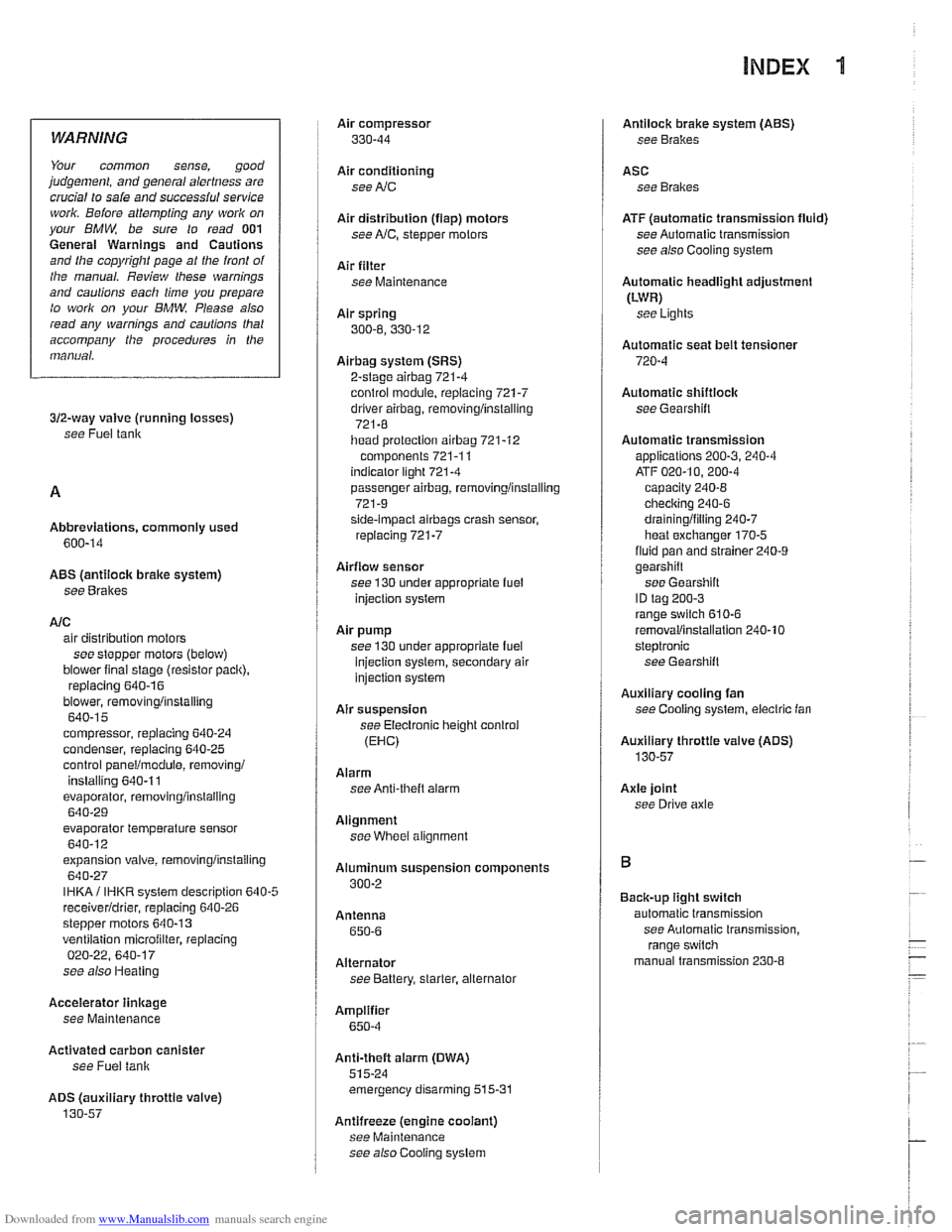
INDEX 'tl
WARNING
Your common sense, good
judgemenl, and general alertness are
crucial to sale and successiul service
worlr. Belore attempting any work on
your
BMM be sure lo read 001
General Warnings and Cautions
and the
copyriglll page at the front 01
the manual. Review these warnings
and
caulions each lime you prepare
lo work on your BMW. Please also
read any warnings and cautions that
accompany
tile procedures in the
manual.
312-way valve (running losses)
see Fuel tank
Abbreviations, commonly used 600-14
ABS (antilock brake system)
see
Bral(es
A/C air distribution motors
see stepper motors (below)
blower final stage (resistor pack),
replacing
640-16
blower, removinglinslalling
640-1 5
compressor, replacing
640-24 condenser, replacing 64045
control panellmodule, removing1
installing
640-1 1
evaporakr, removinglinstalling 640-29
evaporator temperature sensor
640-12 expansion valve, removinglinstailing
640-27
IHKA/ IHKR system description 640-5
receiveridrier, replacing 640-26
stepper motors 640-1 3 ventilation microiilter, replacing
020-22. 640-17
see also Heating
Accelerator
iinlcage
see Maintenance
Activated carbon canister
see Fuel tank
ADS (auxiliary throttle valve)
130-57
Air compressor
330-44
Air conditioning
see
AIC
Air distribution (flap) motors
seeNC, stepper motors
Air filter see Maintenance
Air spring
300-6, 330-12
Airbag system (SRS)
2-stage
airbag 721-4
control module, replacing 721-7 driver airbag, removinglinstalling
721-8
iiead protection airbag 721-12 components 721-1 1
indicator
lighl721-4
passenger airbag, removinglinstalling
721-9 side-impact airbags crash sensor,
replacing
721-7
Airflow sensor see 130 under appropriate
fuel
injection system
Air pump
see 130 under appropriate fuel
injection system, secondary air
injection system
Air suspension
see Electronic height control
(EHC)
Alarm
see Anti-theft alarm
Alignment see
Wheei alignment
Aluminum suspension components
300-2
Antenna 650-6
Alternator see Battery, starter, alte rnator
Amplifier
650-4
Anti-theft alarm (DWA)
515-24 emergency disarming 515-31
Antifreeze (engine coolant)
see Maintenance
see also Cooling system
Antilock brake system (ABS) see Brakes
ASC see Brakes
ATF (automatic transmission fluid)
see Automatic transmission
see also Cooling systern
Automatic headlight adjustmenl
(LWR) see Lights
Automatic seat belt tensioner
720-4
Automatic shiftloclc
see
Gearshift
Automatic transmission
applications
200-3, 240-4
ATF 020-10, 200-4
capacity 240-8 checking 240-6
drainingifilling 240-7
heat exchanger 170-5
fluid pan and strainer 240-9 gearshift
see Gearshift
ID tag
200-3 range switch 610-6
removaliinstallation 240-10
steptronic see Gearshift
Auxiliary cooling fan
see
Coollng system, electric Ian
Auxiliary throttle valve (ADS)
130-57
Axle joint
see Drive axle
Back-up light switch
automatic transmission see Automatic transmission. range switch
- .~.~~~
manual transmission 230-8 -
- I