Speed sensor BMW 528i 1998 E39 Workshop Manual
[x] Cancel search | Manufacturer: BMW, Model Year: 1998, Model line: 528i, Model: BMW 528i 1998 E39Pages: 1002
Page 33 of 1002
Downloaded from www.Manualslib.com manuals search engine
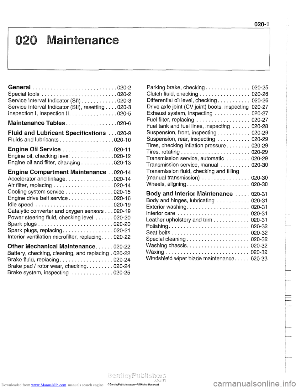
020 Maintenance
General ........................... .02 0.2
Special tools ........................ .02 0.2
Service Interval Indicator (Sll) ........... .02 0.3
Service Interval Indicator (Sll), resetting ... .02 0.3
Inspection I, Inspection 11 ............... .02 0.5
Maintenance Tables ................ .02 0.6
Fluid and Lubricant Specifications .. .02 0.9
Fluids and lubricants ................. .02 0.10
Engine Oil Service ................ .02 0.1 I
Engine oil. checking level ............. .02 0.12
Engine oil and filter. changing .......... .02 0-13
Engine Compartment Maintenance . .02 0.14
Accelerator and linkage ............... .02 0.14
Air filter. replacing ................... .02 0.1 4
Cooling system service ............... .02 0.15
Engine drive belt service .............. .02 0.16
Idlespeed .......................... 020-19
Catalytic converter and oxygen sensors .. .02 0.19
Power steering fluid, checking level ..... .02 0.20
Spark plugs ........................ .02 0.20
Spark plugs, replacing ................ .02 0.21
Interior ventilation microfilter, replacing ... .02 0.22
Other Mechanical Maintenance ..... .02 0.22
Battery, checking. cleaning. and replacing .02 0-22
Brake fluid. replacing ................. .02 0-24
Brake pad 1 rotor wear. checking ........ .02 0.24
Brake system, inspecting ............. .02 0.25
Parking brake. checking ............... 020-25
Clutch fluid. checking ................. 020-26
Differential oil level. checking ........... 020-26
Drive axle joint (CV joint) boots. inspecting 020-27
Exhaust system. inspecting ............ 020-27
Fuel filter. replacing .................. 020-27
Fuel tank and fuel lines. inspecting ...... 020-28
Suspension. front. inspecting ........... 020-29
Suspension. rear. inspecting ........... 020-29
Tires. checking inflation pressure ........ 020-29
Tires. rotating ....................... 020-29
Transmission service. automatic ........ 020-29
Transmission service. manual .......... 020-30
Transmission fluid. checking and filling
(manual transmission)
................ 020-30
Wheels. aligning ..................... 020-30
Body and Interior Maintenance ..... 020-31
Body and hinges. lubricating ........... 020-31
Exterior washing ..................... 020-31
Interior care ........................ 020-31
Leather upholstery and trim ............ 020-31
Polishing ........................... 020-32
Seat belts .......................... 020-32
Special cleaning ..................... 020-32
Washing chassis ..................... 020-32
Waxing ............................ 020-32
Windshield wiper blade maintenance ..... 020-33
Page 51 of 1002
Downloaded from www.Manualslib.com manuals search engine
Maintenance
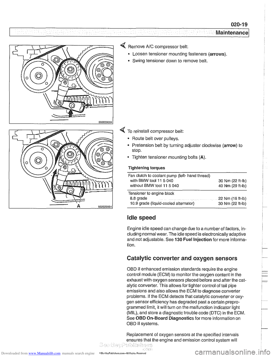
< Remove NC compressor belt:
Loosen tensioner mounting fasteners (arrows)
Swing tensioner down to remove belt.
4 To reinstall compressor belt:
Route belt over pulleys.
* Pretension belt by turning adjuster clockwise (arrow) to
stop.
- Tighten tensioner mounting bolts (A).
Tightening torques
Fan clutch to coolant pump (left- hand thread)
with BMW tool
11 5 040
30 Nm (22 ft-lb)
without BMW tool 11 5 040
40 Nm (29 ft-lb)
Tensioner to engine block
8.8 grade
22 Nm (16 ft-lb)
10.9 grade (Ilquid-cooled alternator) 30 Nm (22 ft-lb)
Idle speed
Engine idle speed can change due to a number of factors, in-
cluding normal wear. The idle speed is electronically adaptive
and not adjustable. See
130 Fuel Injection for more informa-
tion.
Catalytic converter and oxygen sensors
OBD II enhanced emission standards require the engine
control module (ECM) to monitor the oxygen content in the
exhaust with oxygen sensors placed before and after the cat-
alytic converter. This allows for tighter control of tail pipe
emissions and also allows the ECM to diagnose converter
problems. If the ECM detects that catalytic converter or oxy-
gen sensor efficiency has degraded past a certain
prepro-
grammed limit, it will turn on the malfunction indicator light
(MIL), and store a diagnostic trouble code (DTC) in the ECM.
See OBD On-Board Diagnostics for more information on
OBD
ll systems.
Replacement of oxygen sensors at the specified intervals
he engine and emission control system will
Page 103 of 1002
Downloaded from www.Manualslib.com manuals search engine
11 3-9
Cylinder Head Removal and Installation
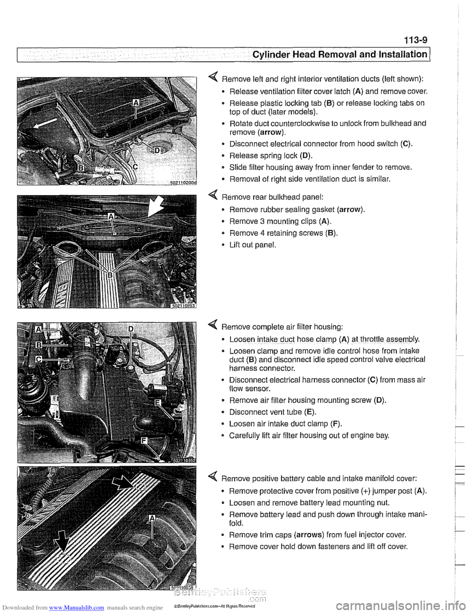
< Remove left and right interior ventilation ducts (left shown):
Release ventilation filter cover latch (A) and remove cover.
Release plastic locking tab
(6) or release locking tabs on
top of duct (later models).
Rotate duct counterclockwise to unlock from bulkhead and
remove (arrow).
Disconnect electrical connector from hood switch
(C).
Release spring lock (D).
Slide filter housing away from inner fender to remove.
Removal of right side ventilation duct is similar.
Remove rear bulkhead panel: Remove rubber sealing
gasket (arrow).
0 Remove 3 mounting clips (A).
Remove
4 retaining screws (6).
Lift out panel.
< Remove complete air filter housing:
Loosen
intake duct hose clamp (A) at throttle assembly.
Loosen clamp and remove idle control hose from
~ntake
duct (6) and disconnect Idle speed control valve electr~cal
harness connector.
Disconnect
electr~cal harness connector (C) from mass alr
flow sensor.
Remove air filter housing mounting screw (D).
Disconnect vent tube
(E).
Loosen air intake duct clamp (F).
Carefully lift air filter housing out of engine bay.
4 Remove positive battery cable and intake manifold cover:
Remove protective cover from positive (+)jumper post (A).
Loosen and remove battery lead mounting nut.
Remove battery lead and push down through intake mani-
fold.
Remove trim caps (arrows) from fuel injector cover.
Remove cover hold down fasteners and lift off cover.
Page 117 of 1002
Downloaded from www.Manualslib.com manuals search engine
- --
Cylinder Head Removal and Installation 1 --
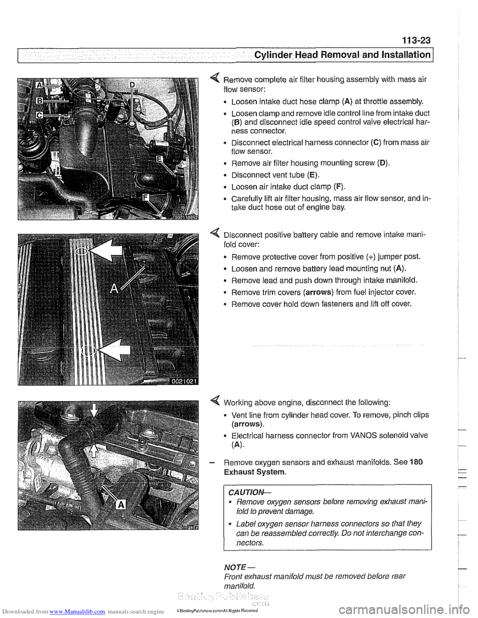
< Remove complete air filter housing assembly with mass air
flow sensor:
Loosen
intalte duct hose clamp (A) at throttle assembly.
Loosen clamp and remove idle control line from intake duct
(B) and disconnect idle speed control valve electrical har-
ness connector.
Disconnect electrical harness connector
(C) from mass air
flow sensor.
Remove air filter housing mounting screw
(D).
Disconnect vent tube (E).
. Loosen air intalte duct clamp (F).
Carefully lifl air filter housing, mass air flow sensor, and in-
take duct hose out of engine bay.
4 Disconnect positive battery cable and remove intake rnani-
fold cover:
Remove protective cover from positive (+)jumper post.
Loosen and remove battery lead mounting nut (A).
Remove lead and push down through intake manifold.
* Remove trim covers (arrows) from fuel injector cover.
Remove cover hold down fasteners and lifl off cover.
4 Worlting above engine, disconnect the following:
Vent line from cylinder head cover. To remove, pinch clips
(arrows).
Electrical harness connector from VANOS solenoid valve
(A).
- Remove oxygen sensors and exhaust manifolds. See 180
Exhaust System.
CAUTION-
Remove oxygen sensors before removing exhaust mani-
fold to prevent damage.
Label oxygen sensor harness connectors so that they
can be reassembled correctly Do not interchange con-
nectors.
NOTE-
Front exhaust manifold must be removed before rear
manifold.
Page 262 of 1002
Downloaded from www.Manualslib.com manuals search engine
Camshaft Timing Chain Timing chains, removing
(M52 engine)
Camshaft timing chain removal on M52 engines requires en-
gine oil pan removal.
Special
BMW sewice tools are needed for timing chain re-
moval and installation procedures. The special tools assure
propertiming of thevalvetrain. Precise marks to
setthe timing
on the camshafts are not provided for reassembly. Read the
procedures through before beginning the job.
NOTE-
If the camshafts are not properly timed, the pistons can con-
tact the valves.
- Remove VANOS control unit. See VANOS control unit, re-
moving (M52 engine).
- Remove radiator cooling fan and shroud. See 170 Radiator
and Cooling System.
- Drain cooling system. See 170 Radiator and Cooling Sys-
tem.
- Remove coolant hoses from thermostat housing and remove
thermostat housing from front of cylinder head.
- Loosen bolts for coolant pump pulley.
- Remove drive belts for alternator and AIC compressor. See
020 Maintenance.
- Remove coolant pump pulley.
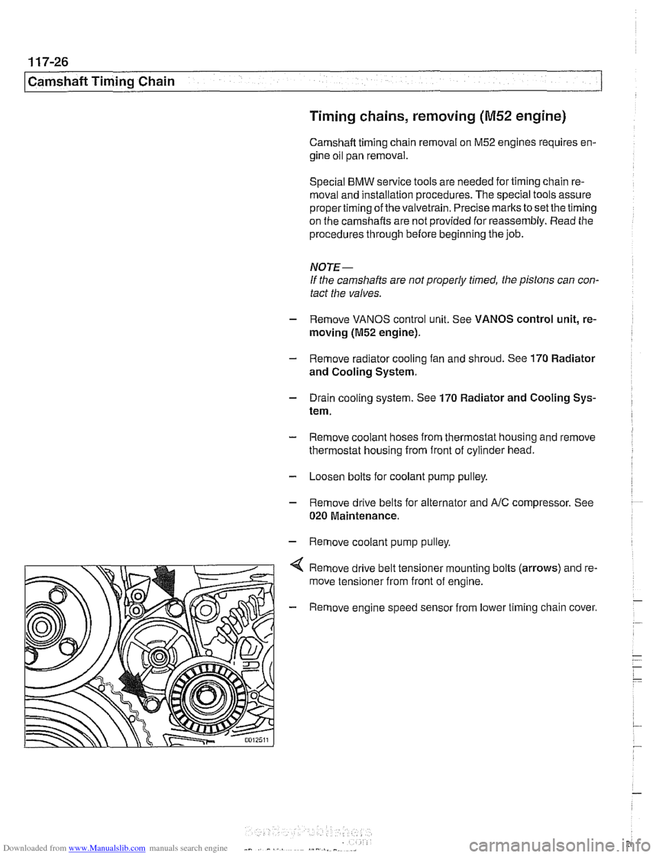
Remove drive belt tensioner mounting bolts (arrows) and re-
move tensioner from front of engine.
- Remove engine speed sensor from lower timing chain cover.
Page 334 of 1002
Downloaded from www.Manualslib.com manuals search engine
.
[Lubrication System
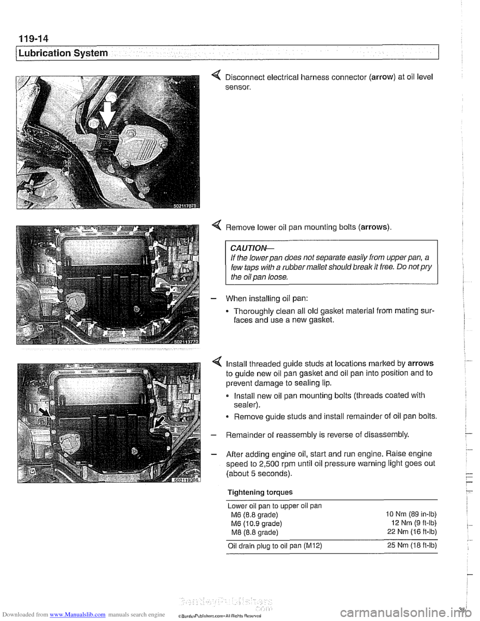
< Disconnect electrical harness connector (arrow) at oil level
sensor.
< Remove lower oil pan mounting bolts (arrows)
CAUTIOI\C
If the lowerpan does not separate easily from upperpan, a
few taps with a rubber mallet should break it free. Do
notpry
the oil pan loose.
- When installing oil pan:
Thoroughly clean all old
gasltet material from mating sur-
faces and use a new gasket.
4 Install threaded guide studs at locations marked by arrows
to guide new oil pan
gasltet and oil pan into position and to
prevent damage to sealing lip.
- Install new oil pan mounting bolts (threads coated with
sealer).
Remove guide studs and install remainder of oil pan bolts.
- Remainder of reassembly is reverse of disassembly
- After adding engine oil, start and run engine. Raise engine
speed to 2,500 rpm until oil pressure warning light goes out
(about 5 seconds).
Tightening torques Lower oil pan to upper
oil pan
M6 (8.8 grade) 10 Nm (89 in-lb)
M6 (10.9 grade) 12 Nm (9 ft-lb)
M8 (8.8 grade) 22 Nm (16 ft-lb)
Oil drain plug to oil pan (M12) 25 Nm (18 ft-lb)
Page 349 of 1002
Downloaded from www.Manualslib.com manuals search engine
120 lgnition System
...................... General
Special tools ...................
Warnings and cautions ...........
Engine management .............
................. lgnition system
Ignition system. troubleshooting
....
... Oscilloscope diagnostic diagrams
................ Misfire detection
............. Ignition System Service 120-9
.................... Ignition firing order 120-9
.............. Disabling ignition system 120-10
................... Checking for spark 120-1 0
lgnition coil assembly.
................. testing and replacing 120-1 0
.............. Crankshaftspeedsensor 120-12
............. Camshaft position sensors 120-1 4
...................... Knocksensors 120-16
Page 353 of 1002
Downloaded from www.Manualslib.com manuals search engine
Lnition switch
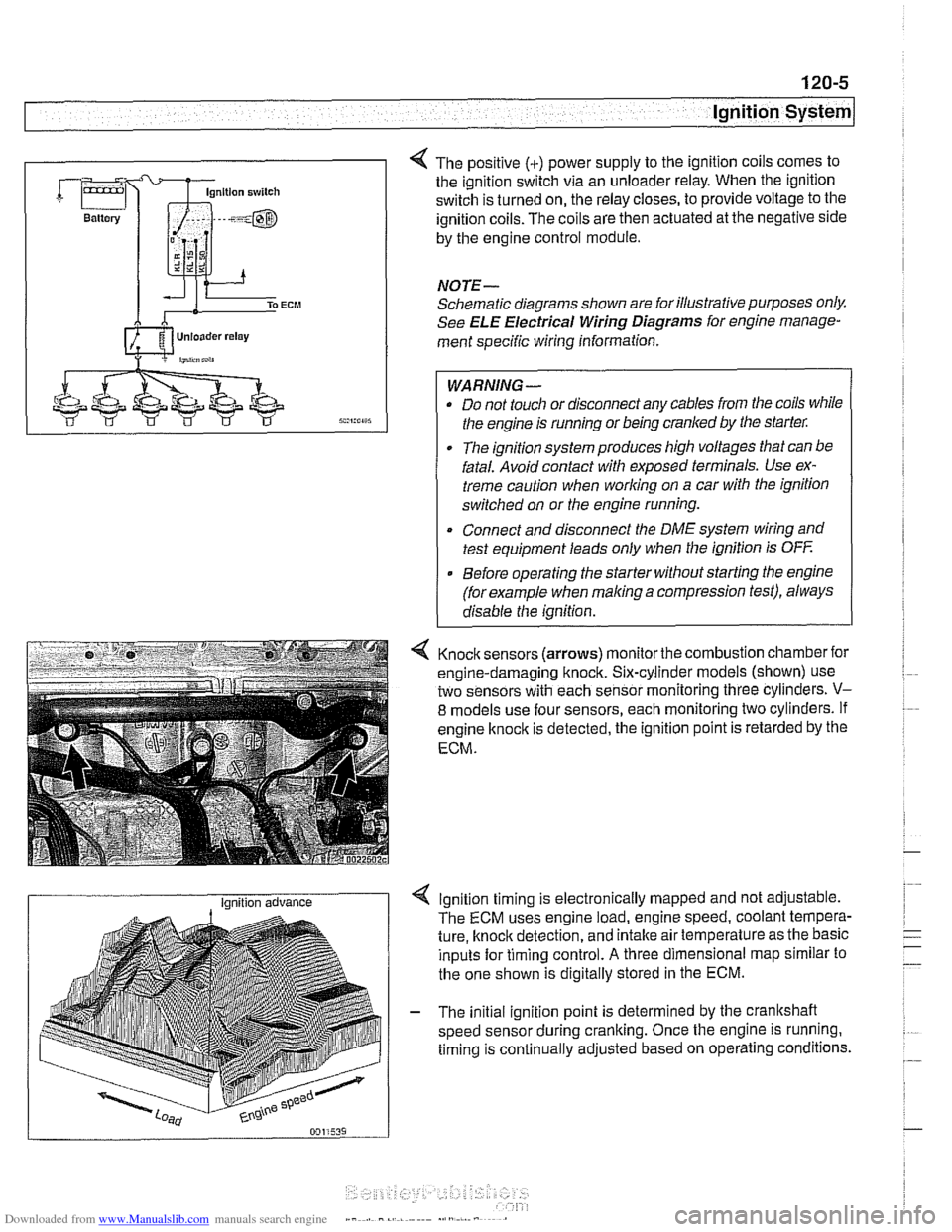
4 The positive (+) power supply to the ignition coils comes to
the ignition switch via an unloader relay. When the ignition
switch is turned on, the relay closes, to provide voltage to the
ignition coils. The coils are then actuated at the negative side
by the engine control module.
NOTE-
Schematic diagrams shown are for illustrative purposes only.
See ELE Electrical Wiring Diagrams for engine manage-
ment specific wiring information.
WARNING- Do not touch or disconnect any cables from the coils while
the engine is running or being cranked by the starter:
The ignition system produces high voltages that can be
fatal. Avoid contact with exposed terminals. Use ex-
treme caution when
working on a car with the ignition
switched on or the engine running.
* Connect and disconnect the DME system wiring and
test equipment leads only when the ignition is
OFF
Before operating the starter without starting the engine
(for example when
making a compression test), always
disable the ignition.
4 Knock sensors (arrows) monitor the combustion chamber for
engine-damaging knock. Six-cylinder models (shown) use
two sensors with each sensor monitoring three cylinders.
V-
8 models use four sensors, each monitoring two cylinders. If
engine
knock is detected, the ignition point is retarded by the
ECM.
I Ignition advance Ignition timing is electronically mapped and not adjustable.
The ECM uses engine load, engine speed, coolant tempera-
ture, knock detection, and intake air temperature as the basic
inputs for timing control.
A three dimensional map similar to
the one shown is digitally stored in the ECM.
- The initial ignition point is determined by the crankshaft
speed sensor during cranking. Once the engine is running.
timing is continually adjusted based on operating conditions.
Page 360 of 1002
Downloaded from www.Manualslib.com manuals search engine
120-1 2
ignition System
Crankshaftspeedsensor
Crankshaft speed sensor, replacing (M52, M52 TU and
M54 engines)
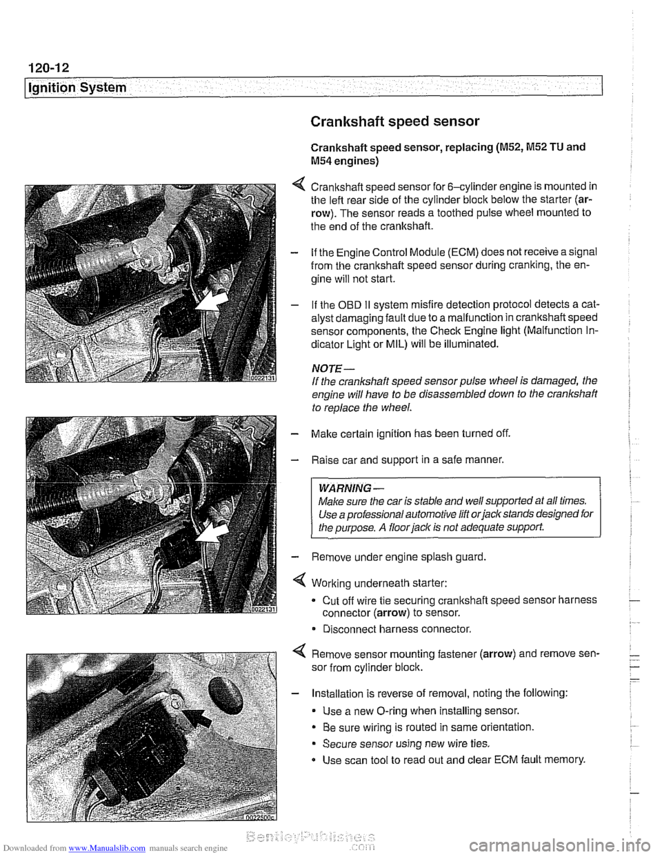
4 Crankshaft speed sensor for 6-cylinder engine is mounted in
the left rear side of the cylinder block below the starter (ar-
row). The sensor reads a toothed pulse wheel mounted to
the end of the crankshaft.
- if the Engine Control Module (ECM) does not receive a signal
from the crankshaft speed sensor during cranking, the en-
gine will not start.
- If the OBD II svstem misfire detection ~rotocol detects a cat- - - ~~
alysr oarnagin; faLlt oJe to a ma I-nclion in crandshafi speeo
sensor components. Ine Check Engine
lignr (Malfuncrion In-
dicator Light or MIL) will be illuminated.
NOTE-
If the crankshaft speed sensor pulse wheel is damaged, the
engine will have to be disassembled down to the crankshaft
to
reolace the wheel.
- Make certain ignition has been turned off.
- Raise car and support in a safe manner.
WARNING -
Make sure the car is stable and well supported at all times.
Use a professional automotive lift orjacltstands designed for
the ouroose.
A floor iaclc is not adequate support.
- Remove under engine splash guard
4 Working underneath starter:
Cut off wire tie securing crankshaft speed sensor harness
connector (arrow) to sensor.
* Disconnect harness connector.
4 Remove sensor mounting fastener (arrow) and remove sen-
sor from cylinder block.
- Installation is reverse of removal, noting the following:
Use a new O-ring when installing sensor.
Be sure wiring is routed in same orientation.
Secure sensor using new wire ties.
Use scan tool to read out and clear ECM fault memory.
Page 361 of 1002
Downloaded from www.Manualslib.com manuals search engine
ignition System
Crankshaft speed sensor, replacing (M62 and M62TU
engines)
The crankshaft speed sensor reads a toothed pulse wheel
mounted on the flywheel.
If the Engine Control Module(ECM)
does not receive an impulse signal from the crankshaft speed
sensor during
cranking, the engine will not start. If the OBD II
system misfire detection protocol detects a catalyst damag-
ing fault due to a malfunction in the crankshaft speed sensor
components, the Check Engine light (Malfunction
Indicator
Light or MIL) will be Illuminated.
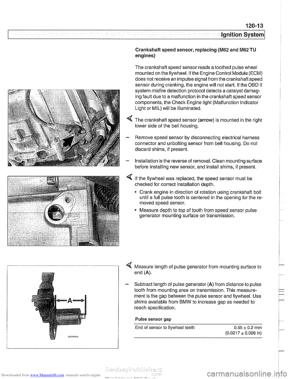
4 The crankshaft speed sensor (arrow) is mounted in the right
lower side of the bell housing.
- Remove speed sensor by disconnecting electrical harness
connector and unbolting sensor from bell housing. Do not
discard shims, if present.
- Installation is the reverse of removal. Clean mounting surface
before installing new sensor, and install shims, if present.
< If the flywheel was replaced, the speed sensor must be
checked for correct installation depth.
* Crank engine in direction of rotation using crankshaft bolt
until a full pulse tooth is centered in the opening for the re-
moved speed sensor.
Measure depth ro top of tooth from speed sensor p~lse
generator mounting s~rface on transmission.
4 Measure length of pulse generator from mounting surface to
end (A).
- Subtract length of pulse generator (A) from distance to pulse
tooth from mounting area on transmission. This measure-
ment is the gap between the pulse sensor and flywheel. Use
shims available from BMW to increase gap as needed to
reach specification.
Pulse sensor
gap
End of sensor to flywheel teeth 0.55 + 0.2 rnrn
(0.0217 t 0.008 in)