Speed sensor BMW 528i 1998 E39 User Guide
[x] Cancel search | Manufacturer: BMW, Model Year: 1998, Model line: 528i, Model: BMW 528i 1998 E39Pages: 1002
Page 379 of 1002
Downloaded from www.Manualslib.com manuals search engine
Battery, Starter, ~lternatorl
Charging system quick-check
Use a digital multimeter to measure voltage across the bat-
tery terminals with key off and then again with engine running.
Battery voltage should be about 12.6 volts with key off and be-
tween 13.5 and 14.5 volts with engine running.
NOTE-
The regulated voltage (engine running) should be between
13.2 and 14.5, depending on temperature andoperating con-
ditions.
If the voltage is higher than 14.8, the voltage regula-
tor or
mulitfunction controller is most likely faulty
Check for clean and tight battery cables. Check ground cable
running from negative
(-) battery terminal to chassis and
ground cable running from engine to chassis. Check alterna-
tor drive belt condition and tension.
Charging system, checking
CAUTIOI\C
* Do not disconnect the battery while the engine is running.
Damage to the alternator and/or engine electronic systems
may result.
Only use a digital multimeter when testing charging
system components.
--7
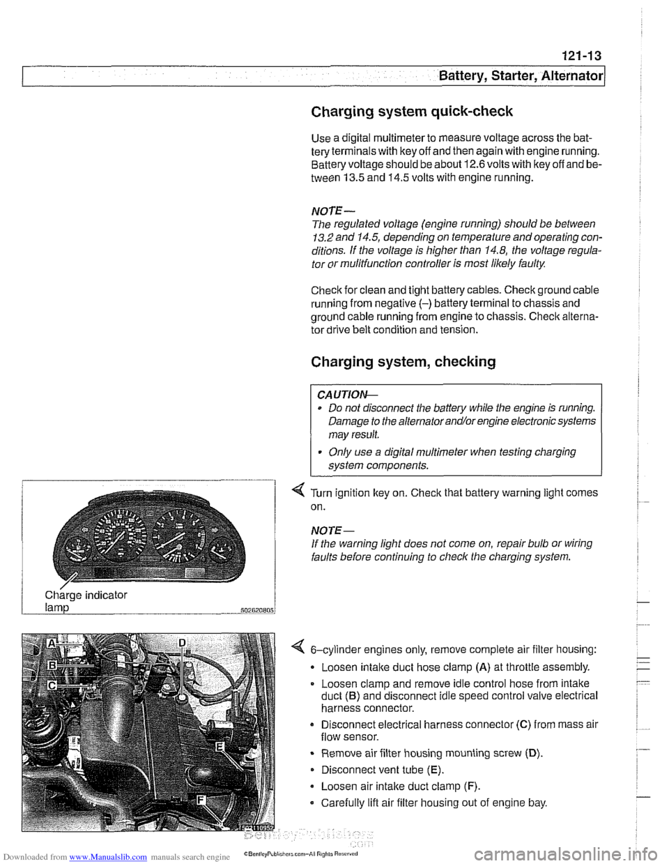
4 Turn ignition key on. Check that battery warning light comes
on.
NOTE-
If the warning light does not come on, repair bulb or wiring
faults before continuing to checlc the charging system.
/ Charge indicator
502820805
4 6-cylinder engines only, remove complete air filter housing:
Loosen
intake duct hose clamp (A) at throttle assembly.
Loosen clamp and remove idle control hose from intake
duct
(B) and disconnect idle speed control valve electrical
harness connector.
Disconnect electrical harness connector
(C) from mass air
flow sensor.
Remove air filter housing mounting screw
(D).
Disconnect vent tube (E).
Loosen air intake duct clamp (F).
Carefully lift air filter housing out of engine bay.
Page 381 of 1002
Downloaded from www.Manualslib.com manuals search engine
Battery, Starter, ~lternatorl
Alternator, removing and installing
(6-cylinder engine)
A replacement alternator should have the same rating as the
original. Alternator manufacturer and ampere rating are nor-
mally marked on the alternator housing.
- Disconnect negative (-) battery cable.
CAUTION-
Prior to disconnecting the batteg read the battery discon-
nection cautions given
in 001 General Warnings and Cau-
I tions.
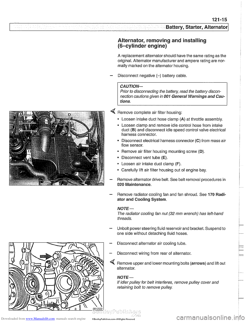
Remove complete air filter housing:
Loosen intake duct hose clamp
(A) at throttle assembly.
Loosen clamp and remove idle control hose from intake
duct
(B) and disconnect idle speed control valve electrical
harness connector.
Disconnect electrical harness connector
(C) from mass air
flow sensor.
* Remove air filter housing mounting screw (D),
Disconnect vent tube (E).
Loosen air intake duct clamp (F).
Carefully lifl air filter housing out of engine bay.
Remove alternator drive belt. See belt removal procedures in
020 Maintenance.
- Remove radiator cooling fan and fan shroud. See 170 Radi-
ator and Cooling System.
NOTE-
The radiator cooling fan nut (32 mm wrench) has left-hand
threads.
- Unbolt power steering fluid reservoir and bracket. Suspend to
one side without detaching fluid hoses.
- Disconnect alternator air cooling tube.
- Disconnect wiring from rear of alternator.
'4 Remove upper and lower mounting bolts (arrows) and lift
alternator.
If idler pulley for belt interferes, remove pulley cover and
retaining bolt to remove pulley. out
Page 386 of 1002
Downloaded from www.Manualslib.com manuals search engine
I Battery, Starter, Alternator
- Check for battery voltage at terminal 50 of starter motor with
key in start position. If voltage is not present, check wiring be-
tween ignition switch and starter terminal. Check the EWS
system and other inputs that disrupt terminal
56 to the start-
er. See ELE Electrical
Wiring Diagrams. If voltage is
present and no other visible wiring faults can be found, prob-
lem is most likely in starter motor.
Starter, removing and installing
(6-cylinder engine)
The starter is removed from below. Access to starter bolts is
difficult. Be sure to have the proper tools on hand before pro-
ceeding.
NOTE-
Access to the starter wiring is very limited. Forbetteraccess,
it may be necessary to remove the intake manifold.
- Disconnect negative (-) battery cable.
CAUTIOI\C
Prior to disconnecting the battern read the baltery discon-
nection cautions
in OOlGeneral Cautions and Warnings.
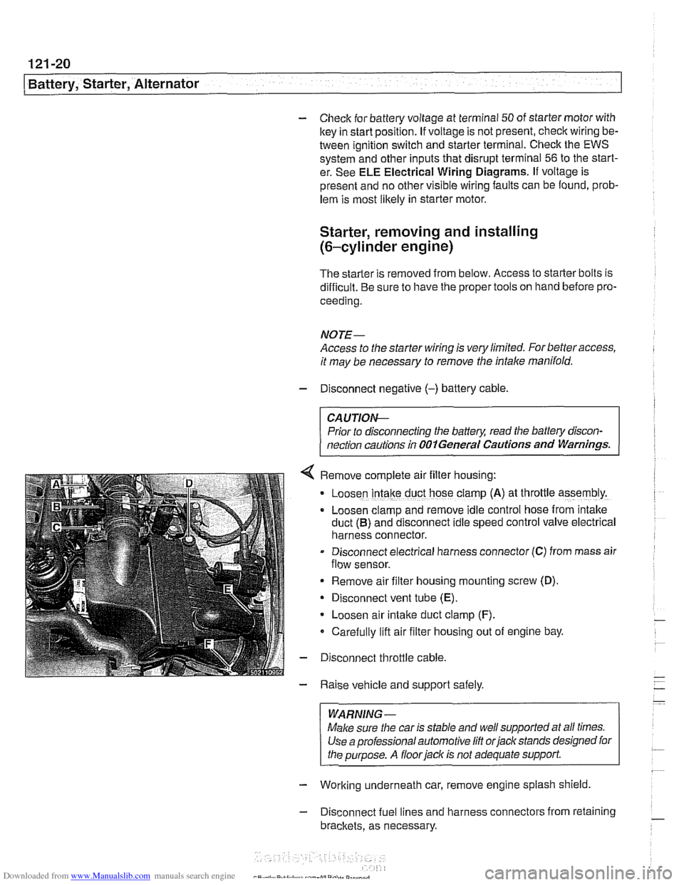
Remove complete air filter hous~ng:
Loosen intake duct hose clamp (A) at throttle assembly.
Loosen clamp and remove idle control hose from intake
duct
(B) and disconnect idle speed control valve electrical
harness connector.
Disconnect electrical harness connector
(C) from mass air
flow sensor.
Remove air filter housing mounting screw (D)
Disconnect vent tube
(E).
Loosen air intake duct clamp (F).
Carefully lift air filter housing out of engine bay.
Disconnect throttle cable.
Raise vehicle and support safely.
WARNING-
Make sure the car is stable and well supported at all times.
Use a professional automotive
lift orjack stands designed for
the purpose. A
floorjaclc is not adequate support
- Working underneath car, remove engine splash shield
- Disconnect fuel lines and harness connectors from retaining
brackets, as necessary.
Page 391 of 1002
Downloaded from www.Manualslib.com manuals search engine
130-1
130 Fuel injection
General ........................... .I3 0.2
Tools and test equipment .............. .I3 0.3
Warnings and cautions ................ .I3 0.5
Fuel Supply ....................... .I3 0.6
Relieving system fuel pressure .......... .I3 0.6
Siemens MS 41 . 1. ................... 1 30-7
ECM relay. testing .................... .I3 0.7
Mass air flow (MAF) sensor.
checking and replacing
................ .I3 0.9
Engine coolant temperature (ECT) sensor.
testing and replacing
.................. 130-10
Intake air temperature (IAT) sensor.
testing and replacing
................. .I3 0.1 1
Throttle position sensor (TPS).
testing and replacing
.................. 130-1 2
ldle speed control valve.
checking and replacing
............... .I3 0.1 3
Fuel injectors. checking and replacing .... 130-15
Evaporative emissions. overview ....... .I3 0.1 6
Secondary air injection. overview ....... .I3 0-17
Engine control module (ECM).
removing and installing
................ 130-18
Siemens MS 41.1 ECM pin assignments . .I3 0.19
Siemens MS 42.0 and MS 43.0. ..... .I3 0.23
ECM relay. testing ................... .I3 0.27
Mass air flow (MAF) sensor.
checking and replacing
............... .I3 0.28
Engine coolant temperature (ECT) sensor.
testing and replacing
................. .I3 0.30
Intake air temperature (IAT) sensor.
testing and replacing
................. .I3 0.31
MS 42.0 throttle valve assembly. replacing . 130-32
MS 43.0 throttle valve assembly. replacing . 130-35
Throttle cable. adjusting (MS 42.0) ...... .I3 0.38
ldle speed control valve. checking
and replacing
....................... .I3 0.38
Evaporative emissions control diagrams . . 130- 39
Evaporative emissions control.
(MS
42.0 and MS 43.0). .............. .I3 0.39
Engine control module (ECM).
removing and installing
................ 130-40
Siemens MS 42.0 and MS 43.0
ECM pin assignments ................. 130-41
Bosch M5.2 (M62 up to 911997)
BOSC~ M5.2.1 (M62 911997 to 911998) 130-46
M5.2 system features ................. 130-47
M5.2.1 system features ............... 130-47
ECM relay. testing ................... 130-49
Oxygen sensors. checking ............. 130-51
Fuel injectors. checking and replacing .... 130-52
Mass air flow (MAF) sensor. replacing .... 130-53
ldle speed control valve. testing
and replacing
....................... 130-54
Throttle position sensor (TPS).
testing and replacing
................. 130-55
Engine coolant temperature (ECT) sensor.
testing and replacing
................. 130-55
Intake air temperature (IAT) sensor.
testing and replacing
................. 130-57
Auxiliary throttle valve (ADS) (M62 and
M62 TU engine). replacing ..... 130-57
Evaporative system pressure
leak diagnosis. overview
(5.2.1 only) ..... 130-58
Bosch 5.2 ECM pin assignments
(M62 UP to 911 997) ................... 130-59
~osch 5.2.1 ECM pin assignments
(M62 911 997 to 911 998) ............... 130-62
BOSC~ ME 7.2 ..................... 1 30-66
ME 7.2 system overview ............... 130-67
EDK adaptation ..................... 130-69
ECM relay. checking .................. 130-69
Engine coolant temperature
(ECT) sensor. testing
................. 130-71
Engine coolant temperature
(ECT) sensor. replacing
............... 130-71
Oxygen sensors. replacing ............. 130-72
Fuel injectors. removing and installing .... 130-72
Mass air flow (MAF) sensor.
removing and installing
................ 130-73
Evaporative system pressure
leak diagnosis. overview
............... 130-74
Secondary air injection. overview ........ 130-75
Bosch ME 7.2 ECM pin assignments .... 130-76
Page 392 of 1002
Downloaded from www.Manualslib.com manuals search engine
130-2
/Fuel Injection
This repair group covers service and repair of the Bosch and
Siemens engine management systems used on
1997
through 2002 E39 models. Additional engine management
service and repair information may also be found in the fol-
lowing repair groups:
0 020 Maintenance
120 Ignition System
160 Fuel Tank and Fuel Pump
610 Electrical Component Locations
OBD On Board Diagnostics
NOTE-
Camshaft position sensor, crankshaft speed sensor and
knoclc sensors are covered in 120 Ignition System.
Table a. Engine management system applications
- - ~ ~
1 ~odellmodel year / Engine IDME system I - I
5281, 1997-1 998 IM52. 2.8 liter ISiemens MS 41 .I I 1
528i. 1999ZO00 1~52 TU, 2.8 liter ]siemens MS 42.0 I I
5251, 2001-2002 1~54, 2.5 liter 1 Siemens MS 43.0 I I
530i, 2001-2002 1~54, 3.0 liter ISiemens MS 43.0
5401 1999-2001 1~62 TU, 4.4 liter l~osch ME 7.2
I
OBI) II software and hardware is incorporated in the engine
management control systems. The
OED II system monitors
components that influence exhaust and evaporative emis-
sions. If a problem is detected, the
OED I1 system stores the
associated fault code and condition.
540i. 1997
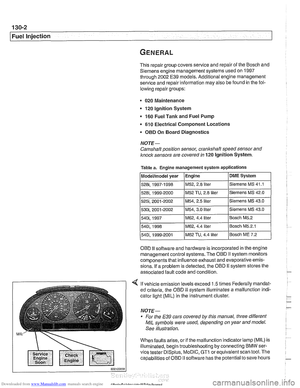
4 If vehicle emission levels exceed 1.5 times Federally mandat-
ed criteria, the
OED II system illuminates a malfunction indi-
cator light
(MIL) in the instrument cluster.
For the
E39 cars covered by this manual, three different
MIL symbols were used, depending on year and model.
See illustration.
When faults arise, or if the malfunction indicator lamp (MIL) is
illuminated, begin troubleshooting by connecting BMW ser-
vice tester
DISplus, MoDiC, GTl or equivalent scan tool. The
capabilities of OBD
II software has the potential to save hours
540i. 1998 IM62, 4.4 liter /Bosch M5.2.1
M62, 4.4 liter Bosch M5.2
Page 399 of 1002
Downloaded from www.Manualslib.com manuals search engine
Fuel Injection I
Mass air flow (MAF) sensor,
checking and replacing
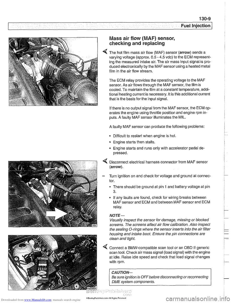
4 The hot film mass air flow (MAF) sensor (arrow) sends a
varying voltage (approx.
0.5 - 4.5 vdc) to the ECM represent-
ing the measured intake air. The air mass input signal is pro-
duced electronically by the
MAFsensorusing a heated metal
film in the air flow stream.
The ECM relay provides the operating voltage to the MAF
sensor. As air flows through the MAF sensor, the film is
-
cooled. To maintain the film at a constant temperature, addi-
tional heating current is necessary. It is this additional current
that is the basis for the input signal.
If there is no output signal from the MAF sensor, the ECM op-
erates the engine using throttle position and engine rpm in-
puts. A faulty MAF sensor illuminates the MIL.
A faulty MAF sensor can produce the following problems:
Difficult to restart when engine is hot.
Engine starts then stalls.
Engine starts and runs only with accelerator pedal de-
pressed.
Disconnect electrical harness connector from MAF sensor
(arrow).
- Turn ignition on and check for voltage and ground at connec-
tor.
There should be ground at pin
1 and battery voltage at pin
3.
If any faults are found, check for wiring breaks between
MAF sensor and ECM and between MAF sensor and ECM
relay.
NOTE-
Visually inspect the sensor for damage, missing or blocked
screens. The screens affect air flow calibration. Also inspect
the sealing O-rings where the sensor inserts into the air
filter
housing and intake boot. Ensure the pin connections are
clean and tight.
4 Connect a BMW-compatible scan tool or an OBD II generic
scan tool. Check air mass signal (load signal) with the engine
at idle. Raise idle speed and check that load signal changes
with rpm.
CA UTIOI\C
Be sure ignition is OFFbefore disconnecting or reconnecting r
1 DME svstem components. 1
Page 403 of 1002
Downloaded from www.Manualslib.com manuals search engine
130-1 3
Fuel Injection I
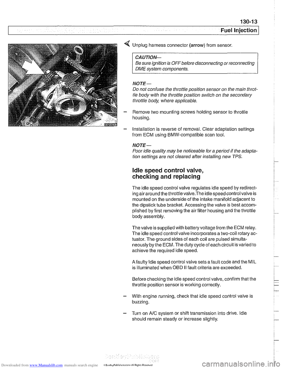
< Unplug harness connector (arrow) from sensor.
CAUTION-
Be sure ignition is OFF before disconnecting or reconnecting
DME system components.
NOTE-
Do not confuse the throttle position sensor on the main Nirot-
tle body with the throttle position switch on the secondary
throttle body, where applicable.
- Remove two mounting screws holding sensor to throttle
housing.
- Installation is reverse of removal. Clear adaptation settings
from ECM using BMW-compatible scan tool.
NOTE-
Poor idle quality may be noticeable for a period if the adapta-
tion settings are not cleared after installing new TPS.
ldle speed control valve,
checking and replacing
The idle speed control valve regulates idle speed by redirect-
inq airaround the throttlevalve.The idlespeed control valve is
mounted on the underside of the intake manifold adjacent to
the dipstick tube bracket. Accessing the valve is best accom-
plished by first removing the air filter housing and the throttle
body assembly.
The valve issupplied with
batteryvoltagefrom the ECM relay.
The idle speed control valve incorporates a two-coil rotary ac-
tuator. The ground sides of each coil are pulsed
sirnulta-
neously by the ECM. The duty cycle of each circuit is varied to
achieve the required idle speed.
Afaulty ldle speed control valve sets afault code and the MIL
is illuminated when
OED II fault criteria are exceeded.
Before checking the idle speed control valve, confirm that the
throttle position sensor is working correctly.
- With engine running, check that idle speed control valve is
buzzing.
- Turn on AIC system or shift transmission into drive. ldle
should remain steady or increase slightly.
Page 407 of 1002
Downloaded from www.Manualslib.com manuals search engine
Fuel Injection 1
NOTE-
The 1998 5281' with MS 41.1 requires a barometric pressure
sensor input signal for activation of the
LDP check. This sen-
sor is located on the passenger side strut tower
fo~lard of
ABS/ASC hydraulic unit.
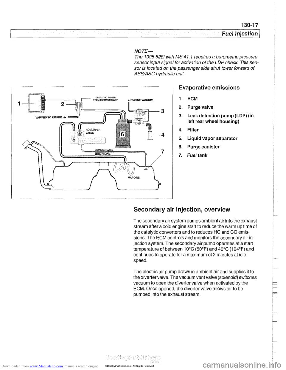
Evaporative emissions
1. ECM
2. Purge valve
3. Leak detection pump (LDP) (in
lefl rear wheel housing)
4. Filter
5. Liquid vapor separator
6. Purge canister
7. Fuel tank
Secondary air injection, overview
The secondary air system pumps ambient air into the exhaust
stream afler a cold engine start to reduce the warm up time of
the catalytic converters and to reduces HC and CO emis-
sions. The ECM controls and monitors the secondary air in-
jection system. The secondary air pump operates at a start
temperature of between 10°C (50°F) and 40°C (104°F) and
continues to operate for a maximum of
2 minutes at idle
speed.
The electric air pump draws in ambient air and supplies it to
the divertervalve. The vacuum ventvalve (solenoid) switches
vacuum to open the divertervalve when activated by the
ECM. Once opened, the diverter valve allows air to be
pumped into the exhaust stream.
Page 410 of 1002
Downloaded from www.Manualslib.com manuals search engine
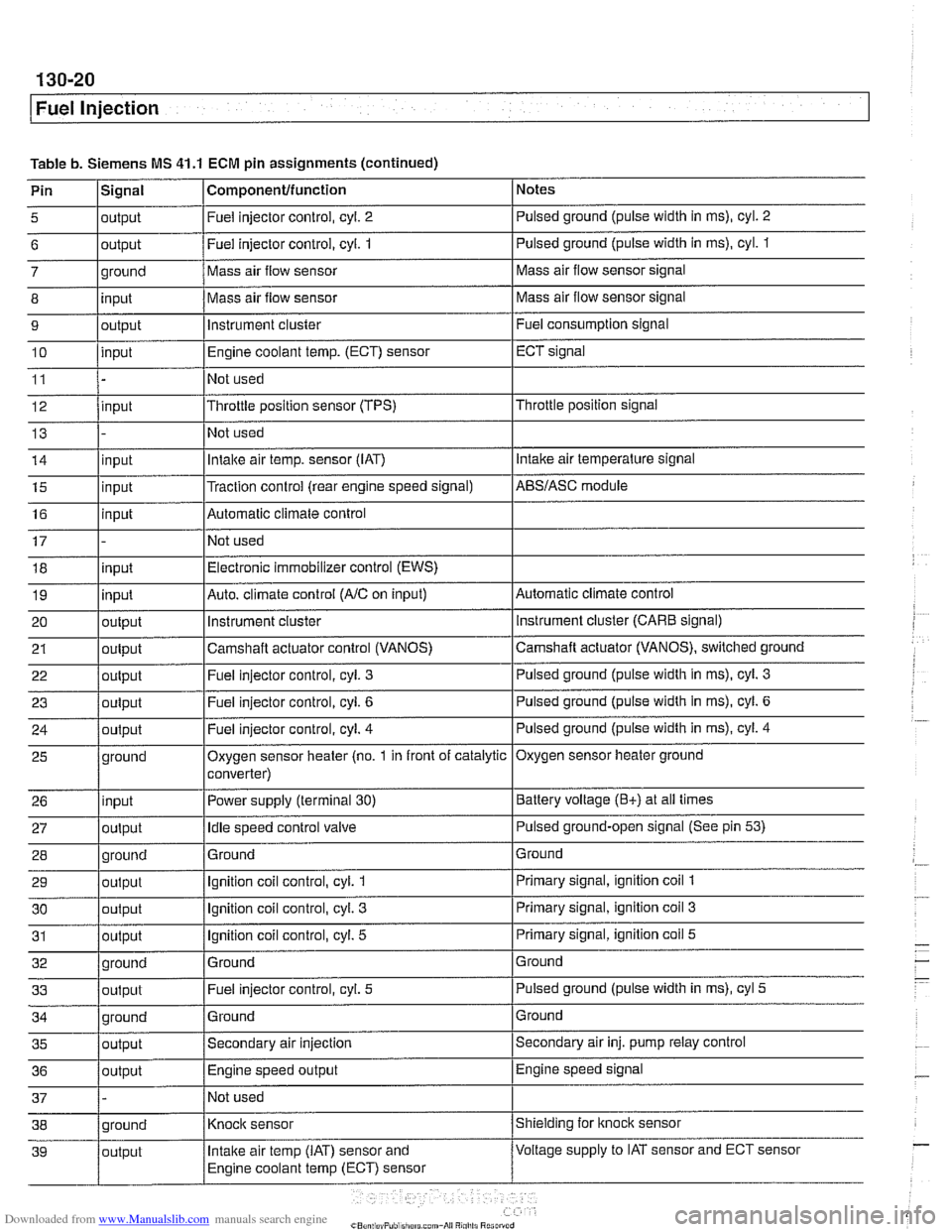
I Fuel Injection
Table b. Siemens MS 41.1 ECM pin assignments (continued)
Pin
l~iqnal I Componentlfunction 1 Notes I - I I
5 loutput I Fuel injector control, cyl. 2 I Pulsed ground (pulse width in ms), cyl. 2 I I I
6 loutput /Fuel injector control, cyi. 1 I Pulsed ground (pulse width in ms), cyl. 1
I I I
14 linput I Intake air temp. sensor (IAT) I Intake air temperature signal
- 7
8
9
10
11
12
13
ground
input
output
input
input
15
16
17 18
19
20
21
22
I - I I
35 loutput /Secondary air injection ISecondary air inj. pump relay control
25
26
27
28
29
30
31
32
33
36
/output I Engine speed output IEngine speed signal
Mass air flow sensor
Mass air flow sensor
instrument cluster
Engine coolant
temp.
(ECT) sensor
Not used
Throttle position sensor (TPS)
Not used
input
input
input
input
output
output
out~ut
37 1 - /Not used I
Mass air flow sensor signal
Mass air flow sensor signal
Fuel consumption signal
ECT signal
Throttle position signal
ground
input
output
ground
output
output
output
ground
output
Traction control (rear engine speed signal) Automatic climate control
Not used Electronic immobilizer control (EWS)
Auto. climate control
(AIC on input)
instrument
cluster
Camshaft actuator control (VANOS)
Fuel iniector control, cvl.
3
AES/ASC module
Automatic climate control instrument cluster (CARE signal)
Camshaft actuator (VANOS), switched ground
Pulsed ground (pulse width in
ms), cyl. 3
Oxygen sensor heater (no. 1 in front of catalytic
converter)
Power supply (terminal
30)
Idle speed control valve
Ground
Ignition coil control, cyl.
1
Ignition coil control, cyl. 3
Ignition coil control, cyl. 5
Ground Fuel injector control, cyl.
5
Oxygen sensor heater ground
Battery voltage
(E+) at all times
Pulsed ground-open signal (See pin
53)
Ground
Primary signal, ignition coil
1
Primary signal, ignition coil 3
Primary signal, ignition coil 5
Ground
Pulsed ground (pulse width in ms), cyl
5
Page 411 of 1002
Downloaded from www.Manualslib.com manuals search engine
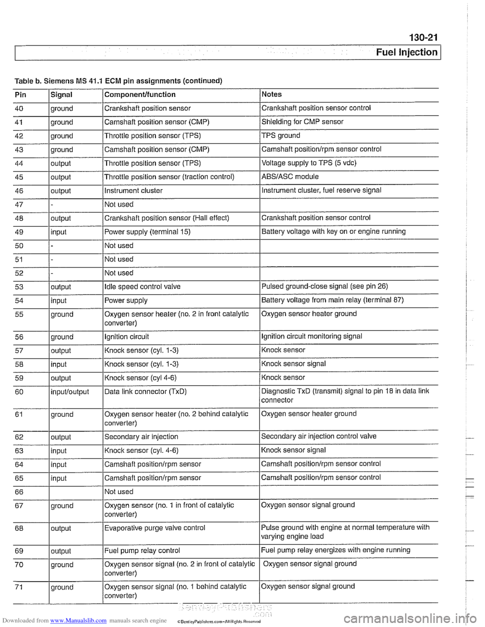
Fuel lniection 1
Table b. Siemens MS 41.1 ECM pin assignments (continued)
Pin
lSiqnal 1 Componentlfunction / Notes I - I I
40 1 ground /Crankshaft position sensor /crankshaft position sensor control I - I I
41 1 ground /Camshaft position sensor (CMP) /shielding for CMP sensor I - I I
42 1 ground I~hrottie position sensor (TPS) /TPS ground
43
44
45
46
47
48
49
50
51 ground
output
output
output
outout
I I I
input
52 53
54
55
56 57
58
59
60
61
62
63
64
65
66 Camshaft position sensor (CMP)
Throttle position sensor (TPS)
Throttle position sensor (traction control)
Instrument cluster
Not used
Crankshaft position sensor (Hall effect)
I~ot used
I I I
Fuel pump relay control Camshaft
positionlrpm sensor control
Voltage
supply to TPS (5 vdc)
ABSIASC module
Instrument cluster, fuel reserve signal
Crankshaft position sensor control
Power supply (terminal 15)
Not used
Not used
output input
ground
ground
output
input
output
inputloutput
ground
output
input
input
input
I I
Battery voltage with key on or engine running
Oxygen sensor signal ground
67
Idle speed control valve
Power supply
Oxygen sensor heater (no. 2 in front catalytic
converter)
Ignition circuit
Knock sensor
(cyl. 1-3)
Knock sensor (cyl. 1-3)
Knock sensor
(cyl4-6)
Data linic connector (TxD)
Oxygen sensor heater (no. 2 behind catalytic
converter)
Secondary air injection
Knock sensor (cyl. 4-6)
Camshaft
positionlrpm sensor
Camshaft
positionlrpm sensor
Not used
Pulse ground with engine at normal temperature with
varying engine load
68 Pulsed ground-close signal (see
pin 26)
Battery voltage from main relay (terminal 87)
Oxygen sensor heater ground
Ignition circuit monitoring signal
Knock sensor
Knock sensor signal
Knock sensor
Diagnostic
TxD (transmit) signal to pin 18 in data link
connector
Oxygen sensor heater ground
Secondary air injection control
valve
Knocic sensor signal
Camshaft positionlrpm sensor control
Camshaft
positionlrpm sensor control
ground Oxygen sensor
(no.
1 in front of catalytic
converter)
output Evaporative purge
valve control