engine control system BMW 528i 1998 E39 Workshop Manual
[x] Cancel search | Manufacturer: BMW, Model Year: 1998, Model line: 528i, Model: BMW 528i 1998 E39Pages: 1002
Page 662 of 1002
Downloaded from www.Manualslib.com manuals search engine
I Steerina and Wheel Alianment
Steering
system
Two types of steering gear are used in the E39 series models.
6-cylinder
(5251, 528i and 530i) models are equipped with
rack and pinion steering. The steering rack is mounted to
an aluminum subframe.
V-8
(540i) models are equipped with a recirculating ball
and nut steering gearbox mounted to a steel subframe.
At low speeds, maximum power assist is provided to ease
parking and city driving. At high speeds, assist is reduced to
ensure stability. The power steering system varies assist
based on engine speed.
Power boost for the steering is provided by an engine-driven
hydraulic pump. A hydraulic control valve is used to control
boost pressure.
The steering wheel connects to the steering gear via an ad-
justable steering column which incorporates a rubber cou-
pling ("guibo") to dampen vibration and noise.
Power steering fluid is supplied from the fluid
reservoir to the
pump and to the steering gear via rubberlmetal hoses.
The return line from the steering gear to the
reservoir loops
into the airstream in front of the radiator and connects to the
steering fluid cooler. The fluid cooler is attached to a cassette
which also includes cooling coils for engine oil, transmission
fluid and AIC condenser.
The steering gear requires no maintenance other than align-
ment and periodic inspection for worn components. Inspect
rubber rack boots
(rack and pinion system) and tie-rod end
boots periodically for tears or damage. Replace
if necessary.
-
NOTE-
The airbag system is traditionally referred to as Supplemen-
tal Restraint System (SRS). The
BMW versfon of SRS used
m the E39 models is known as the Multiple Restraint System - (MRS). - -
Page 664 of 1002
Downloaded from www.Manualslib.com manuals search engine
Steering and Wheel Alignment
Steering system warnings and cautions
WARNING -
The BMW airbag system is complex. Special precautions
must be observed when servicing the system. Serious in-
jury may result if system service is attempted by persons
unfamiliar with the BMW
airbag system and its approved
service procedures. BMW specifies that all inspection and
service should be
peiformed by an authorized BMW deal-
e,:
The BMW E39 is equipped with an airbag mounted in
the steering wheel. The
airbag is an explosive device
and should be treated with extreme caution. Always fol-
low the
airbag removal procedure as outlined in 721
Airbag System (SRS).
BMW airbags are equipped with a bacli-up power sup-
ply inside the
airbag control module. A 5 second wait-
ing period should be observed after the battery cable
has been disconnected. This will allow the reserve
power supply to discharge.
Do not reuse self-locking nuts. They are designed to
be used only once and may fail if reused. Always re-
place them with new locliing nuts.
* Do not install bolts and nuts coated with undercoating
wax, as correct tightening torque cannot be assured.
Always clean the threads with solvent before installa-
tion, or install new parts.
Do not attempt to weld or straighten any steering com-
ponents. Always replace damagedparts.
CAUTION--
- Some E39 models are equipped with aluminum suspen.
sion components. The following cautions apply:
Due to the chemical and corrosion characteristics of
aluminum, do not bring into contact with battery acid.
Do not clean with wire brushes with brass or iron bris-
tles. Only use brushes with stainless steel bristles.
Do
not expose to flying sparks from grindinghutting op-
erations.
Do not subject to steel welding splashes.
* Do not expose to temperatures over 80% (176°F).
even for short periods. Temperatures in painting iacili-
ties are not a problem.
Page 665 of 1002
Downloaded from www.Manualslib.com manuals search engine
320-7
Steering and Wheel ~liqnmentl
STEERING WHEEL
Steering wheel, removal and installation
WARNING -
The BMWairbag system (Supplemental Restraint System or
SRS) is complex. Special precautions must be observed
when servicing. Serious injury may result if
SRS system serv-
ice is
attempted by persons unfamiliar with the BMW SRS
and its approved service procedures. BMW specifies that all
inspection andservice should be preformed by an authorized
BMW dealer.
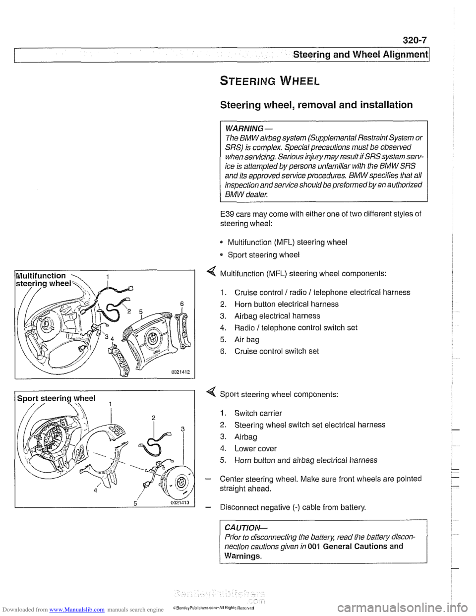
E39 cars may come with either one of two different styles of
steering wheel:
Multifunction (MFL) steering wheel
* Sport steering wheel
4 Multifunction (MFL) steering wheel components:
1. Cruise control 1 radio 1 telephone electrical harness
2. Horn button electrical harness
3. Airbag electrical harness
4. Radio / telephone control switch set
5. Air bag
6. Cruise control switch set
Sport steering wheel
3
5 0021413
4 Sport steering wheel components:
1. Switch carrier
2 Steering wheel switch set electrical harness
3. Airbag
4. Lower cover
5. Horn button and airbag electrical harness
- Center steering wheel. Make sure front wheels are pointed
straight ahead.
- Disconnect negative (-) cable from battery.
CA UTIOP&
Prior to disconnecting the battern read the battew discon-
nection cautions given in
001 General Cautions and
Warnings.
-
Page 666 of 1002
Downloaded from www.Manualslib.com manuals search engine
320-8
Steering and Wheel Alignment
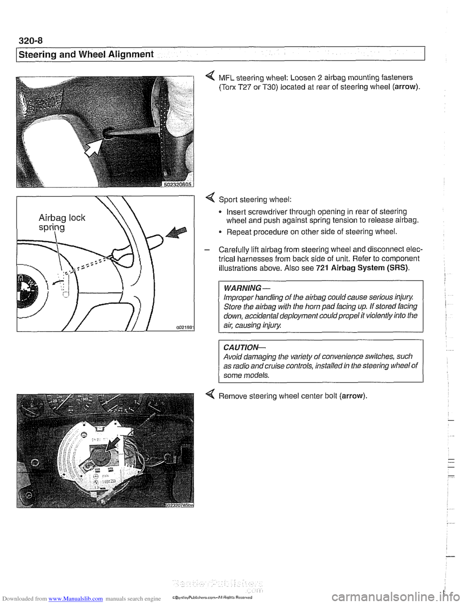
4 MFL steering wheel: Loosen 2 airbag mounting fasteners
(Torx T27 or T30) located at rear of steering wheel (arrow).
4 Sport steering wheel:
Insert screwdriver through opening in rear of steering
wheel and push against spring tension to release
airbag.
Repeat procedure on other side of steering wheel.
- Carefully lift airbag from steering wheel and disconnect elec-
trical harnesses from
back side of unit. Refer to component
illustrations above. Also see
721 Airbag System (SRS).
Improper handling of the airbag could cause serious injury.
Store the
airbag with the horn pad facing up. If stored facing
down, accidental deployment couldpropel it violently into the
Avoid damaging the variety of convenience switches, such
as radio and cruise controls, installed in the steering wheel of
4 Remove steering wheel center bolt (arrow).
Page 705 of 1002
Downloaded from www.Manualslib.com manuals search engine
--
C. -- -- - -- Rear ~us~ensionl
Depending on year and model applications, the Sport Wagon
rear suspension may be equipped with:
Conventional shock absorbers and coil springs
Electronic height control (EHC) system which incorporates
air springs
NOTE-
. Suspension and EHC troubleshooting is covered in 300
Suspension, Steering and Brakes-General.
EHC system repairs, other than air spring replacement,
are covered in Electronic height control
(EHC) compo-
nent replacement.
Replace shock absorbers and springs in pairs only.
Rear shock absorber, removing and
installing
- Raise car and remove rear wheels,
WARNING-
Male sure that the car is firmly supported on jack stands de-
signed for the purpose. Place jack stands underneath struc-
tural chassis points. Do not place
jack stands under
suspension parts.
CAUTION-
If working on a vehicle with compressedairshock absorbers,
disable air supply pump by disconnecting electrical plug be-
fore performing any repairs. Pump is located beneath a cover
under the spare tire in the floor of the cargo compartment.
- Support swing arm from below
CAUTIOG
The shock absorber prevents the drive axle and wlieel bear-
ing carrier from dropping too far. Supporting the wheel bear-
ing carrier before disconnecting the shock absorber
mounting fasteners prevents damage to the
brake hose,
parking
brake cable and drive axle CVjoints.
- Working in cargo compartment, remove carpet. Remove tri-
angular upper shock mount covers located beside spare tire
well.
- If applicable: Detach air supply line from shock absorber.
Plug ports and lines to keep out dirt.
Page 708 of 1002
Downloaded from www.Manualslib.com manuals search engine
Rear Suspension
Air spring, removing and installing
CAUTION-
If vehicle is driven with airspring depressurized, the airspring
will be permanently damaged and must be replaced.
An air spring is made from a flexible rubber material which
forms an airtight cavity. It is pressurized by an air supply
pump activated by an electronic control unit to provide a
vari- . . able spring rate depending on vehicle load
CAUTIOIG
Disable air supply pump by disconnecting electrical plug
before performing any repairs. Pump is located beneath a
cover under the spare tire in the floor of
the cargo compart-
ment.
When removing and installing air connections, extreme
cleanliness must be followed. Small dirt particles can
cause leakage in the system.
Remove luggage compartment floor mat.
- Working above air spring, loosen quick coupling screw con-
nection to allow
air pressure to escape.
- Once pressure has been reduced, retighten screw.
Tightening torque Quick coupling screw
to air pump 2 Nm (18 in-lb)
- Remove quick coupler. Plug openings to keep dirt out,
- Remove air spring mounting clips.
- Raise car and remove rear wheels.
Make sure the car is firmly supported on jack stands de-
signed for the purpose. Place jack stands underneath struc-
tural chassis points. Do not place
jaclc stands under
suspension parts.
- Working underneath rear suspension, lift wheel bearing car-
rier to relieve rear spring tension. Then unbolt air spring
mounting bolt from seat on wheel bearing carrier. Remove air
spring.
NOTE-
Left and right air springs are different. The left air spring is
marked with a red identification
marl. The right air spring is
marked with a blue identification mark.
Page 722 of 1002
Downloaded from www.Manualslib.com manuals search engine
330-26
/ Rear Suspension
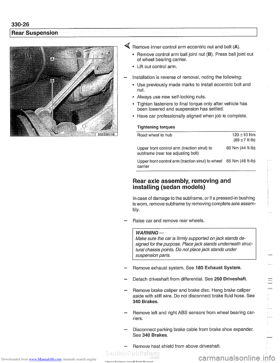
Remove inner control arm eccentric nut and bolt (A)
Remove control arm ball joint nut (6). Press ball joint out
of wheel bearing carrier.
Lifl out control arm.
Installation is reverse of removal, noting the following:
Use previously made
marks to install eccentric bolt and
nut.
Always use new self-locking nuts.
Tighten fasteners to final torque only after vehicle has
been lowered and suspension has settled.
0 Have car professionally aligned when job is complete.
Tightening
torques
Road wheel to hub 120klONm
(89 i7 ft-lb)
Upper front control arm (traction strut) to 60
Nm (44
ft-lb)
subframe (rear toe adjusting bolt)
Upper front control arm (traction strut) to wheel
65 Nm (48 ft-lb)
carrier
Rear axle assembly, removing and
installing (sedan models)
In case of damage to the subframe, or if a pressed-in bushing
is worn, remove
subframe by removing complete axle assem-
bly.
- Raise car and remove rear wheels.
WARNING-
Make sure the car is firmly supported on jack stands de-
signed for the purpose. Place jack stands underneath struc-
tural chassis points. Do not place
jack stands under
suspension parts.
- Remove exhaust system. See 180 Exhaust System
- Detach driveshaft from differential. See 260 Driveshaft.
- Remove brake caliper and brake disc. Hang brake caliper
aside with stiff wire. Do not disconnect brake fluid hose. See
340 Brakes.
- Remove lefl and right ABS sensors from wheel bearing car-
riers.
- Disconnect parking brake cable from brake shoe expander.
See 340 Brakes.
- Remove heat shield from above driveshaft.
Page 731 of 1002
Downloaded from www.Manualslib.com manuals search engine
330-35
Rear Suspension
- Remainder of installation is reverse of removal, noting the fol-
lowing.
Always use new self-loclting nuts.
Make sure all threaded bolts, nuts and mating suriaces are
clean.
Make sure long lower strut bushing fits in hole in wheel
bearing carrier.
Tighten fasteners to final torque only after vehicle has
been lowered and suspension has settled.
Stake axle collar nut after tightening.
Tightening torques
ABS pulse sensor to wheel bearing carrier
8 Nm (6 ft-lb)
Brake rotor to hub 16 Nm (12 ft-lb)
Rear brake pad carrier (caliper) to wheel 65
Nm (48
ft-lb)
bearing carrier
Rear axle shaft to hub
(M27) 300 Nm (221 ft-lb)
Rear strut to wheel bearing carrier 127
Nrn (94 ft-lb)
Road wheel to hub
120+10 Nm
(89
i7 ft-lb)
Swing arm to wheel bearing carrier 256
Nrn (189 ft-lb)
Upper front control arm (traction strut) to 65 Nrn
(48
ft-lb)
wheel carrier
Upper rear control arm to wheel carrier 142
Nrn (105
ft-lb)
Rear wheel bearing carrier, removing and
installing (Sport Wagon models)
- Raise rear end of car and remove wheel.
WARNING-
Make sure the car is firmly supported on jack stands de-
signed for the purpose. Place jack stands underneath struc-
tural chassis points. Do not place jack stands under
suspension parts.
Models
with air springs: Disable air supply pump by discon-
necting electricalplug
beforepedormingany repairs. Pump is
located beneath a cover under the spare tire in the floor of the
cargo compartment.
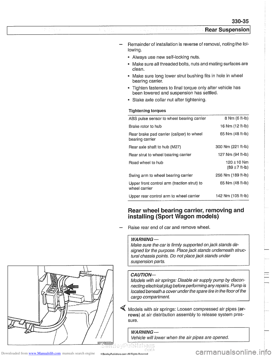
-- 4 Models with air springs: Loosen compressed air pipes (ar-
rows) at air distribution assembly to release system pres-
Page 740 of 1002
Downloaded from www.Manualslib.com manuals search engine
---
Rear Suspension
ELECTRONIC HEIGHT CONTROL
(EHC) COMPONENT REPLACEMENT
Sport Premium rear suspension is an option on Sport Wagon
models and standard on
1999 and later V-8 Sport Wagons.
This suspension incorporates electronic height control
(EHC)
using air springs.
With vehicle lifted off the ground,
if the rear air springs can be
compressed by hand, either the spring is defective or the sys-
tem is depressurized.
Locate
EHC faults using BMW scan tools DIS or MoDiC. EHC
description and some troubleshooting is covered in 300 Sus-
pension, Steering and Brakes-General.
Air spring replacement is covered earlier in this chapter. See
Air spring, removing and installing.
CAUTION-
Maintain high levels of cleanliness around air line connec-
tions when disassembling and assembling air suspension
components. Even
small dirt particles can cause leakage in
the pressurized system.
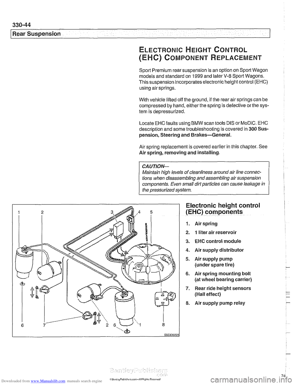
Electronic height control
(EHC) components
1. Air spring
2. 1 liter air reservoir
3. EHC control module
4. Air supply distributor
5. Airsupply pump
(under spare tire)
6. Air spring mounting bolt
(at wheel bearing carrier)
7. Rear ride height sensors
(Hall effect)
8. Air supply pump relay
Page 741 of 1002
Downloaded from www.Manualslib.com manuals search engine
-- I
I: ... . -. Rear Suspension! -- .- -
Air compressor pump relay, removing and
installing
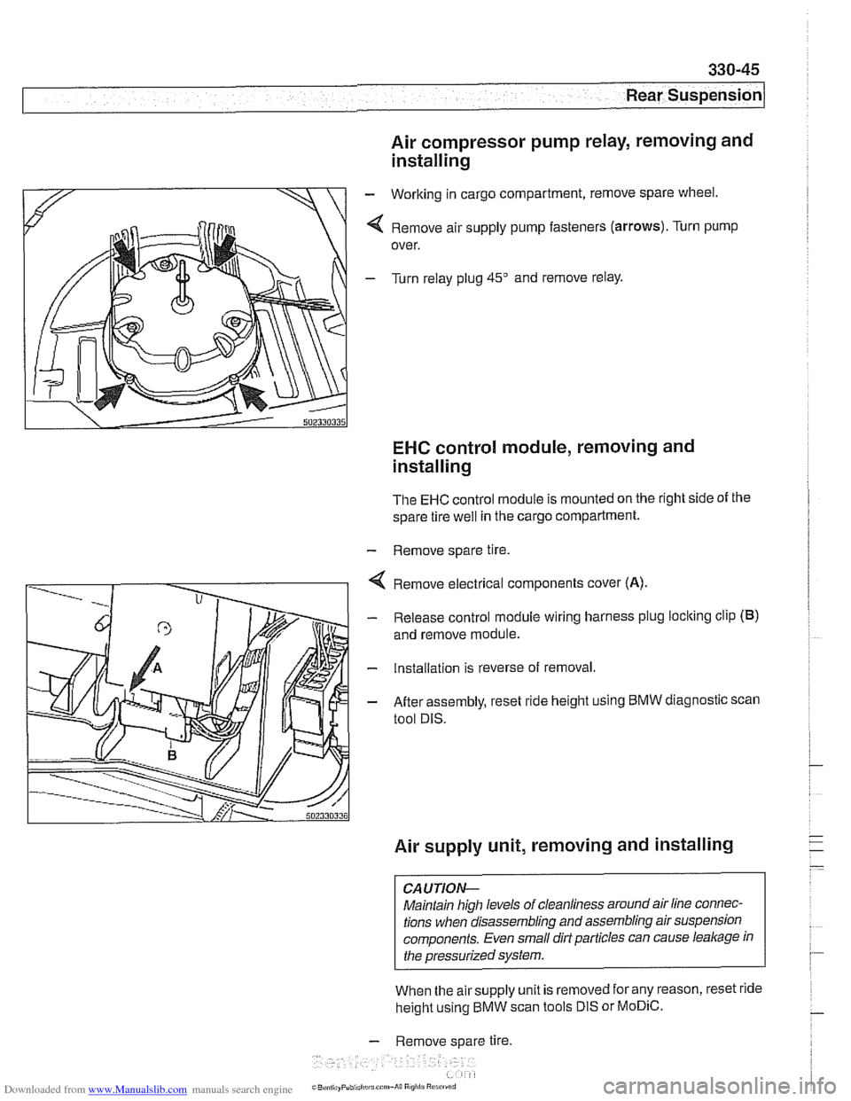
- Working in cargo compartment, remove spare wheel.
4 Remove air supply pump fasteners (arrows). Turn pump
over.
- Turn relay plug 45" and remove relay.
EHC control module, removing and
installing
The EHC control module is mounted on the right side of the
spare tire
well in the cargo compartment.
- Remove spare tire.
4 Remove electrical components cover (A).
- Release control module wiring harness plug loclting clip (B)
and remove module.
- Installation is reverse of removal.
- After assembly, reset ride height using BMW diagnostic scan
tool DIS.
Air supply unit, removing and installing
CAUTION-
Maintain high levels of cleanliness around air line connec-
tions when disassembling and assembling air suspension
components. Even small dirt particles can cause
leakage in
the pressurized system.
When the airsupply unit is removed for any reason, reset ride
height using BMW scan tools DIS or
MoDiC.
- Remove spare tire.
i~B,!n,,ayPubi.l,c~u.c~"~-A~~ R