engine control system BMW 528i 1998 E39 Workshop Manual
[x] Cancel search | Manufacturer: BMW, Model Year: 1998, Model line: 528i, Model: BMW 528i 1998 E39Pages: 1002
Page 905 of 1002
Downloaded from www.Manualslib.com manuals search engine
515-11
Central Lockinq and ~nti-l heft/
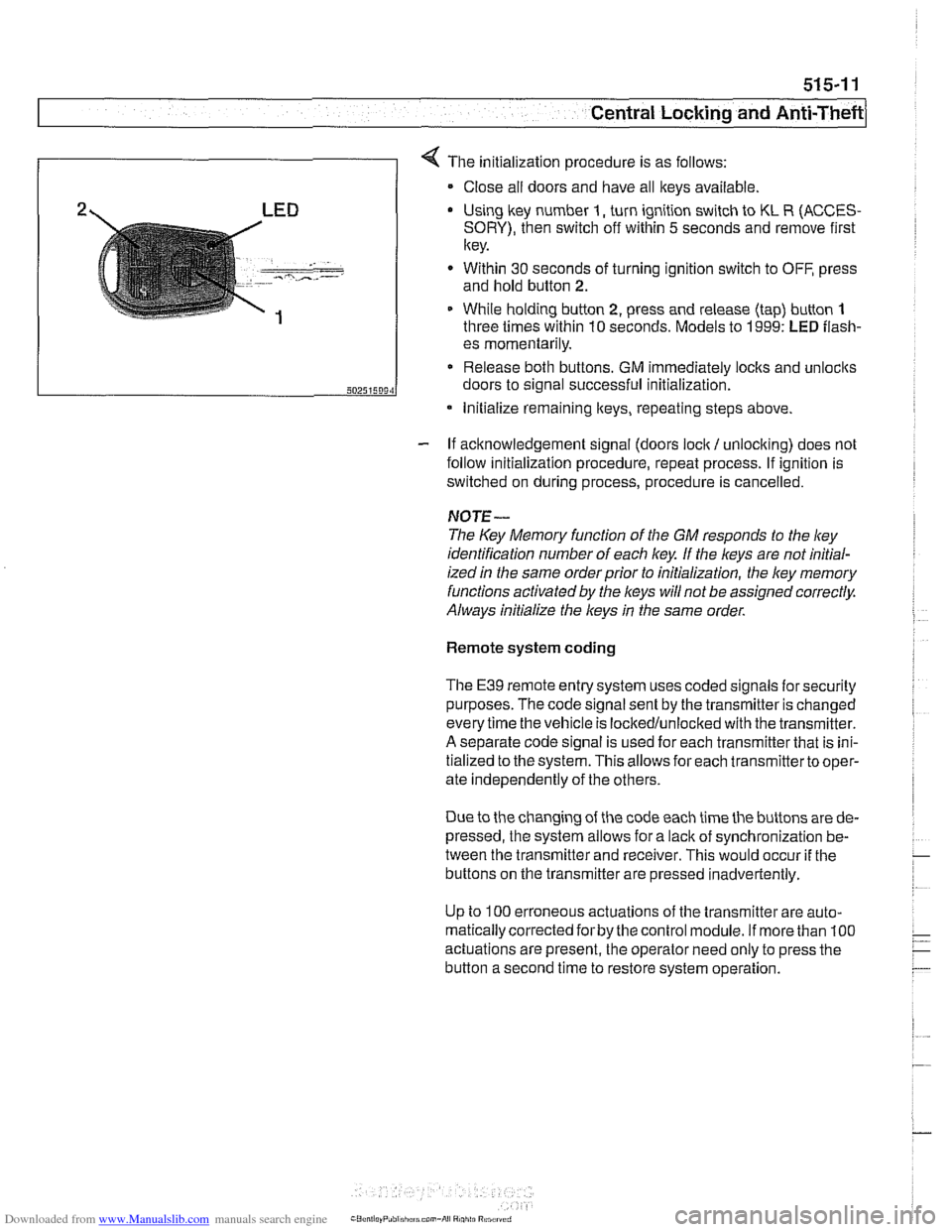
4 The initialization procedure is as follows:
Close ail doors and have all keys available
2 LED Using lkey number I, turn ignition switch to KL R (ACCES-
SORY), then switch off within 5 seconds and remove first
key.
. - -- , ..-.---- - Within 30 seconds of turning ignition switch to OFF, press
and hold button
2.
1 While holding button 2, press and release (tap) button 1
three times within 10 seconds. Models to 1999: LED flash-
- If acknowledgement signal (doors lock / unlocking) does not
follow initialization procedure, repeat process. If ignition is
switched on during process, procedure is cancelled.
50251509‘1
NOTE-
The Key Memory function of the GM responds to the ley
identification number of each key If the keys are not initial-
ized
in the same orderprior to initialization, the ley memory
functions activated by the
l(eys will not be assigned correctly.
Always initialize the keys
in the same order.
es momentarily.
Release both buttons. GM immediately locks and unlocits
doors to signal successful initialization.
Remote system coding
* Initialize remaining lteys, repeating steps above.
The E39 remote entry system uses coded signals for security
purposes. The code signal sent by the transmitter is changed
every time the vehicle is lockedlunlocked with the transmitter.
A separate code signal is used for each transmitter that is ini-
tialized to the system. This allows for each transmitterto oper-
ate independently of the others.
Due to the changing of the code each time the buttons are de-
pressed, the system allows for a
lacit of synchronization be-
tween the transmitter and receiver. This would occur
if the
buttons on the transmitter are pressed inadvertently.
Up to
100 erroneous actuations of the transmitter are auto-
matically corrected
forby the control module. If more than 100
actuations are present, the operator need only to press the
button a second time to restore system operation.
Page 906 of 1002
Downloaded from www.Manualslib.com manuals search engine
51 5-12
I Central Locking and Anti-Theft
Key battery
9
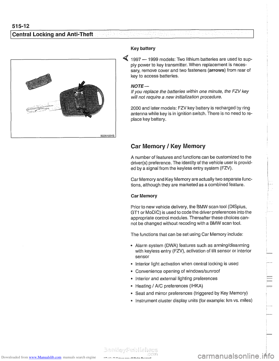
4 1997 - 1999 models: Two lithium batteries are used to sup-
ply power to key transmitter. When replacement is neces-
sary, remove cover and two fasteners (arrows) from rear of
key to access batteries
NOTE-
If you replace the batteries within one minute, the FZV ley
will not require a new initialization procedure.
2000 and later models: FZV key battery is recharged by ring
antenna while ltey is in ignition switch. There is no need to re-
place ltey battery.
Car Memory 1 Key Memory
A number of features and functions can be customized to the
driver(s) preference. The identity of the vehicle user is provid-
ed by a
s~gnal from the keyless entry system (FZV).
Car Memory and Key Memory are actually two separate func-
tions, although they are marketed as a combined feature.
Car Memory
Pr'or ro new
veh c,e de very, the BMW scan roo (DISp us,
GTI or MOD C) is ~sed lo cooc ine driver preierences nro ine
appropriate control modules. Thereafter these choices can-
not be changed without
recoding with a BMW scan tool.
The functions that can be set using Car Memory include:
Alarm system (DWA) features such as armingldisarming
with
lkeyless entry (FZV), activation of tilt sensor or interior
sensor
lnterior light activation when central
locking is used
Convenience opening of
windows/sunroof
lnterior and external lighting preferences
Heating
I A/C preferences (IHKA)
Seat and mirror preferences (triggered by Key Memory)
Instrument cluster display units (for example: km vs. miles)
Page 915 of 1002
Downloaded from www.Manualslib.com manuals search engine
51 5-21
Central Locking and Anti-Theft
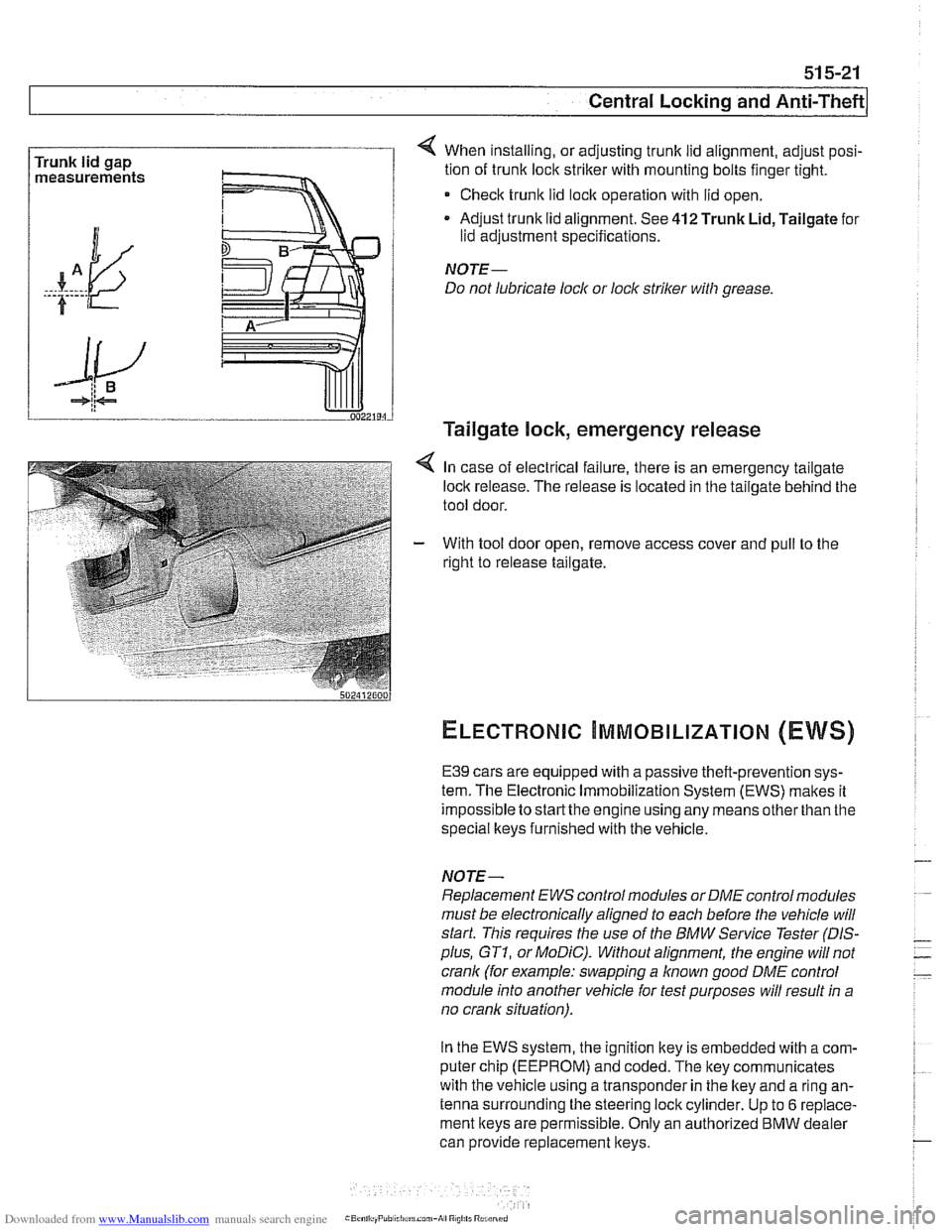
Trunk lid gap
measurements 4 When installing, or adjusting trunk lid alignment, adjust posi-
tion of trunk
loclc striker with mounting bolts finger tight.
* Check trunk lid loclc operation with lid open.
Adjust trunk lid alignment. See
412 Trunk Lid, Tailgate for
lid adjustment specifications.
NOTE-
Do not lubricate lock or lock striker with grease.
Tailgate lock, emergency release
4 In case of electrical failure, there is an emergency tailgate
loclk release. The release is located in the tailgate behind the
tool door.
- With tool door open, remove access cover and pull to the
right to release tailgate.
ELECTRONIC ~MMOBILIZATION (EWS)
E39 cars are equipped with a passive theft-prevention sys-
tem. The Electronic Immobilization System (EWS) makes it
impossible to
startthe engine using any means other than the
special lkeys furnished with the vehicle.
NOTE-
Replacement EWS control modules or DME control modules
must be electronically aligned to each before the vehicle will
start. This requires the use of the BMW Service Tester
(DIS-
plus, GT1, or MoDiC). Without alignment, the engine will not
crank (for example: swapping a
known good DME control
module into another vehicle for test purposes will result in a
no crank situation).
In the EWS system, the ignition key is embedded with
acom-
puter chip (EEPROM) and coded. The key communicates
with the vehicle using a transponder in the lkey and a ring an-
tenna surrounding the steering lock cylinder. Up to
6 replace-
ment keys are permissible. Only an authorized
BMW dealer
can provide replacement keys.
Page 916 of 1002
Downloaded from www.Manualslib.com manuals search engine
Central Locking and Anii-Theft
- If the starter engages, the following EWS inputs are function-
ing normally:
Ignition key
Code function
Transmission range switch or clutch position switch
Engine speed sensor
NO JE -
If a vehicle key is lost or stolen, the electronic authorization
for that key
can be cancelled using the BMW scan and di-
agnostic tools
DISplus, GTl or MoDiC.
Force applied to a ley can damage the electronic circuitry
in the key A damaged ley will not start the engine. In that
case, a new key should be purchased and initialized
by an
authorized BMW dealer.
EWS variations
EWS variations used in E39 cars are shown in E39 EWS ap-
plications
table below.
E39
EWS applications
I I Ifling antenna (surrounds ignition switch) I
System
designation
EWS
II
I I l~ransmitter I receiver module located in right side steering column cover I
E39 production
dates
SOP
- 311 997
I I IEWS 111 (3.2) control module incorporates transmitter1 receiver moduie functions /
Main components, changes, improvements
Key with EEPROM transponder
Control moduie located behind glove compartment, in electrical component panel
Control module located to left of steering column, under dashboard
K-Bus input
Transmitter
I receiver module eliminated
EWS 111 (3.2)
Transmission range selection input from automatic transmission control module
3
11997 - 911997
- EWS ill (3.3) Clutch
Hall-effect switch (replaces transmission range switch input)
911997 - 2002 EWS 111 (3.3) control
module with iSN code burned in (cannot be overwritten during
alignment)
Control module located to left of steering column, under dashboard
Page 918 of 1002
Downloaded from www.Manualslib.com manuals search engine
51 5-24
l~entral Locking and Anti-Theft
ANTI-THEFT SYSTEM (DWA)
When the anti-then system (DWA) is armed, the doors, hood,
windows, trunk lid or tailgate are monitored against forcible
entry by switches and sensors. The vehicle is protected
against being jacked up or towed away by a tilt sensor.
The control electronics for DWA are integrated in the General
Module (GM). In addition to the control electronics, the sys-
tem includes the following components.
* DWA horn
DWA LED indicator
- Tilt sensor
- Monitoring switches and sensors
The system can be armed or disarmed from the driver's door
lock,
trunklid lock, tailgate lockorthe remote transmitter (FZV
Itey). When armed, the alarm horn
soundsfor30seconds and
the low beam headlights and turn signals flash for
5 minutes.
The electronic immobilizer (EWS) is also activated when
DWA is activated.
The alarm is switched off immediately if key is inserted in door
loclt or FZV key button is used.
DWA LED Status
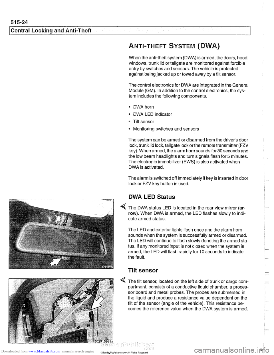
The DWA status LED is located in the rear view mirror (ar-
row). When DWA is armed, the LED flashes slowly to indi-
cate armed status.
The LED and exterior lights flash once and the alarm horn
sounds when the system is successfully armed ordisarmed.
The LED will continue to flash slowly denoting the armed sta-
tus. If any monitored input is not closed when the system is
armed, the LED will flash rapidly for
10 seconds to indicate
the fault.
Tilt sensor
-
4 The tilt sensor, located on the left side of trunlt or cargo com- -
partment, consists of a conductive liquid chamber, a proces-
sor board and metal probes. The probes are submersed in
the liquid and produce a resistance value dependent on the
tilt of the sensor (angle of the vehicle). This resistance be-
comes the reference value when the DWA system is armed.
.-
Page 922 of 1002
Downloaded from www.Manualslib.com manuals search engine
l Seats
This repair group covers removal and installation of the front
and rear seat.
SeatIMirrorlSteering Column Memory
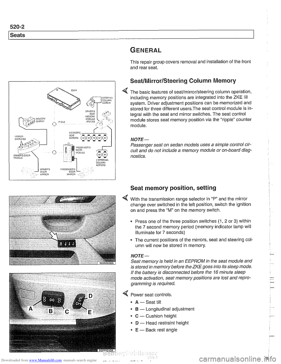
< The basic features of seaffmirrorlsteering column operation,
including memory positions are integrated into the
ZKE Ill
system. Driver adjustment positions can be memorized and
stored for three different
users.The seat control module is in-
tegral with the seat and mirror switches. The seat control
module stores seat memory position via the "ripple" counter
module.
NOTE-
Passenger seat on sedan models uses a simple control cir-
cuit and do not include a memory module or on-board diag-
nostics.
Seat memory position, setting
With the transmission range selector in "P and the mirror
change over switched in the left position, switch the ignition
on and press the
"M" on the memory switch.
Press one of the three position switches
(1, 2 or 3) within
the
7 second memory period (memory indicator lamp will
illuminate for
7 seconds)
- The current positions of the mirrors, seat and steering col-
umn will now be stored in memory.
NOTE- Seat memory is held in an
EEPROM in the seat module and
is stored in memory before the
ZKE goes into its sleep mode.
If the battery is disconnected before the 16 minute sleep
mode activation, seat memorypositions are lost and repro-
gramming is required.
< Power seat controls.
A -Seat tilt
B - Longitudinal adjustment
C - Cushion height
D - Head restraint height
E - Back rest angle
Page 949 of 1002
Downloaded from www.Manualslib.com manuals search engine
721 Airbag System (SRS)
........................... General ............................ 721-2 Airbags 721-8
..... E39Airbags ......................... 721-3 Driver airbag. removing and installing 721-8
Two-stage airbag (MRS 111) ............ .72 1.4 Passenger airbag. removing and installing . 721-9
Airbag indicator light .................. .72 1.4 Door mounted side-impact airbag.
............... Warninas .......................... .72 1.5 removina and installina 721-10 .
..... Head protection airbag components 721
-1 1 Airbag Electronics ................. '721-6 Head protection airbag (HpS) .......... 721-12 MRS ............................... 721-6
MRS
airbag system diagram ........... .72 1.6
MRS control module. replacing ......... .72 1.7
Side-impact crash sensor.
removing and installing
................ .72 1.7
Page 951 of 1002
Downloaded from www.Manualslib.com manuals search engine
721 -3
Airbag System (SRS)
MRS Ill adds the following features:
MRS
Ill employs "smart" technology. Smart technology re-
fers to the control module's programming for the deploy-
ment of the airbags, in stages depending on the severity of
the impact.
Two-stage a~rbag for ooln drver and passenger Alloivs for
a softer
c~snioning elfecl when the airbags are lr ggered at
lighter impact,
MRS
Ill satellite sensors use 2 wire connectors
Rear side
airbags arrive de-activated from the factory and
can only be activated upon written request from the cus-
tomer.
Rear seat head protection is available when ordered with
optional rear seat side airbags.
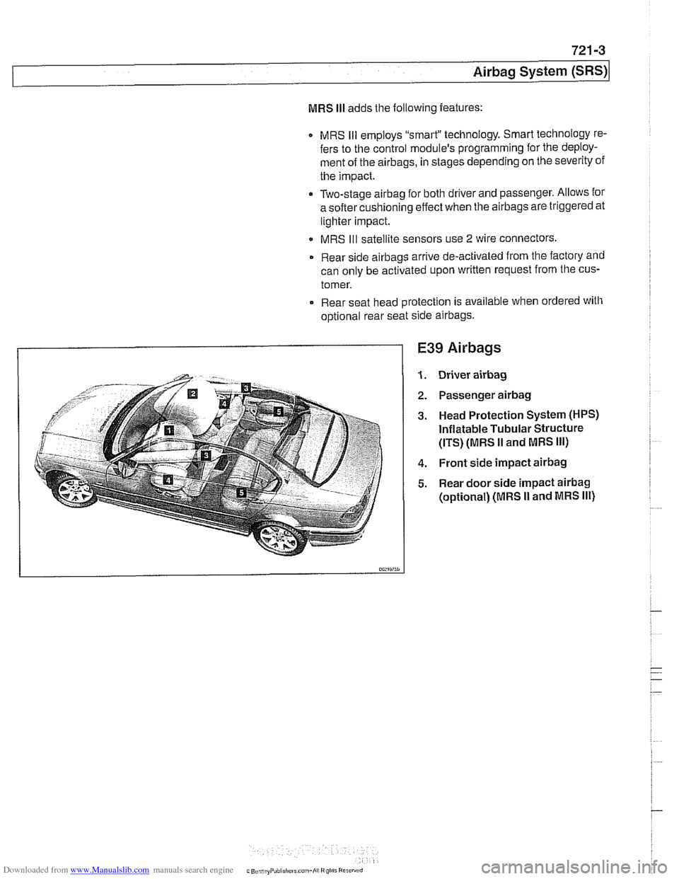
E39 Airbags
Driver airbag
Passenger airbag
Head Protection System (HPS)
Inflatable Tubular Structure
(ITS) (MRS
II and MRS Ill)
Front side impact airbag
Rear door side impact airbag
(optional) (MRS I1 and MRS Ill)
Page 952 of 1002
Downloaded from www.Manualslib.com manuals search engine
I Airbag System (SRS)
Two-stage airbag (MRS Ill)
Beginning with 2000 model year (911 999 production) the front
airbags were changed to a two-stage style airbag. This en-
sures that the force of
airbag inflation is not greater than nec-
essary to provide
protection. The airbags are designed to
Drovide "soit" de~lovment if the acceleration sensor detects a
iow-speed impact, and "hard deployment in higher speed im-
pacts.
NOTE-
A two-stage passenger airbag was used on cars built be-
tween
9/1998 and 3/1999. This pre-smart technology airbag
used two ignition stages. Stage one is designed to ignite first
during an impact. Stage two ignites after a timed period, as
programmed in the MRS
I1 control module.
Airbag indicator light
The MRS control module detects and stores system status
The
airbag indicator light in the instrument cluster displays
the status of the
airbag system when the ignition key is in "ac-
cessory" or
ON positions.
System normal: lndicator light comes on briefly, then goes
out.
- System malfunction: lndicator light fails to come on.
System malfunction: lndicator light comes on briefly, goes
out and lights up again.
The
airbag indicator light also comes on if the seat belt pyro-
technic tensioners have been triggered.
Page 953 of 1002
Downloaded from www.Manualslib.com manuals search engine
Airbag System (SRS)~
Warnings
When servicing airbag equipped cars, the following precau-
tions must be
observed to prevent personal injury.
WARNING-
. If the airbag indicator light is on, there is a risk that the air-
bags will not be triggered in case of an accident Be sure
to have the system inspected and repaired immediately
Airbag(s) are inflated by an explosive device. Handled
improperly or witliout adequate safeguards, the system
can be very dangerous. Special precautions must be
observed prior to any work at or near the airbags.
0 The airbag is a vehicle safety system. Serious injury
may result if system service is attempted by persons
unfamiliar with the BMW
MRS and its approved service
procedures. BMW advises that all inspection and ser-
vice be performed by an authorized BMW dealer.
Always disconnect the battery and cover the negative
(-) battery terminal with an insulator before starting di-
agnostic, troubleshooting or service
work not associat-
ed
with the airbags, and before doing any welding on
the car.
0 After disconnecting the battery, wait 5 seconds before
beginning work on
airbag components.
* If an airbag has been activated due to an accident,
BMW specifies that
airbag components be replaced.
For more information on post-collision
airbag service,
see an authorized BMW dealer.
Do not fire an
airbag unit prior to disposal. It must be
fired by a special disposal company or shipped back to
BMW in the packaging of the new components.
When removing a fired
airbag unit, avoid contact with
the
skin; weargloves. In case ofskin contact, wash with
water.
Do not allow
airbag system components to come in
contact with cleaning solutions or grease. Never sub-
ject
airbag components to temperatures above 167°F
(75°C). When reconnecting the battery, no person
should be inside the vehicle.
Always place an
airbag unit that has been removed
from its
packaging with the paddedside facing upward.
Do not leave an
airbag unit unattended.
0 If the airbag unit or airbag control module has been
dropped from a height of
'/? meter (I//: ft.) or more, the
airbag unit should not be installed.