engine control system BMW 528i 1998 E39 Manual PDF
[x] Cancel search | Manufacturer: BMW, Model Year: 1998, Model line: 528i, Model: BMW 528i 1998 E39Pages: 1002
Page 441 of 1002
Downloaded from www.Manualslib.com manuals search engine
130-51
Fuel Injection
Oxygen sensors, checking
The oxygen sensor provides an input voltage signal [0.2 vdc
(lean) to 0.8 vdc (rich)] to the
ECM based on the oxygen con-
tent in the exhaust gas. To generate voltage, the sensor tem-
perature must exceed 575"
F (300" C). Therefore the sensor
is electrically heated.
NO JE -
The test given below is not a conclusive test of oxygen sen-
sor efficiency and does not test how the oxygen sensor re-
acts to changing conditions. Pin numbers and wire colors
can vary Always check the wiring diagrams to confirm wire
color and pin assignment.
0 The oxygen sensorconnectorplugs are locatednext to the
catalytic converters.
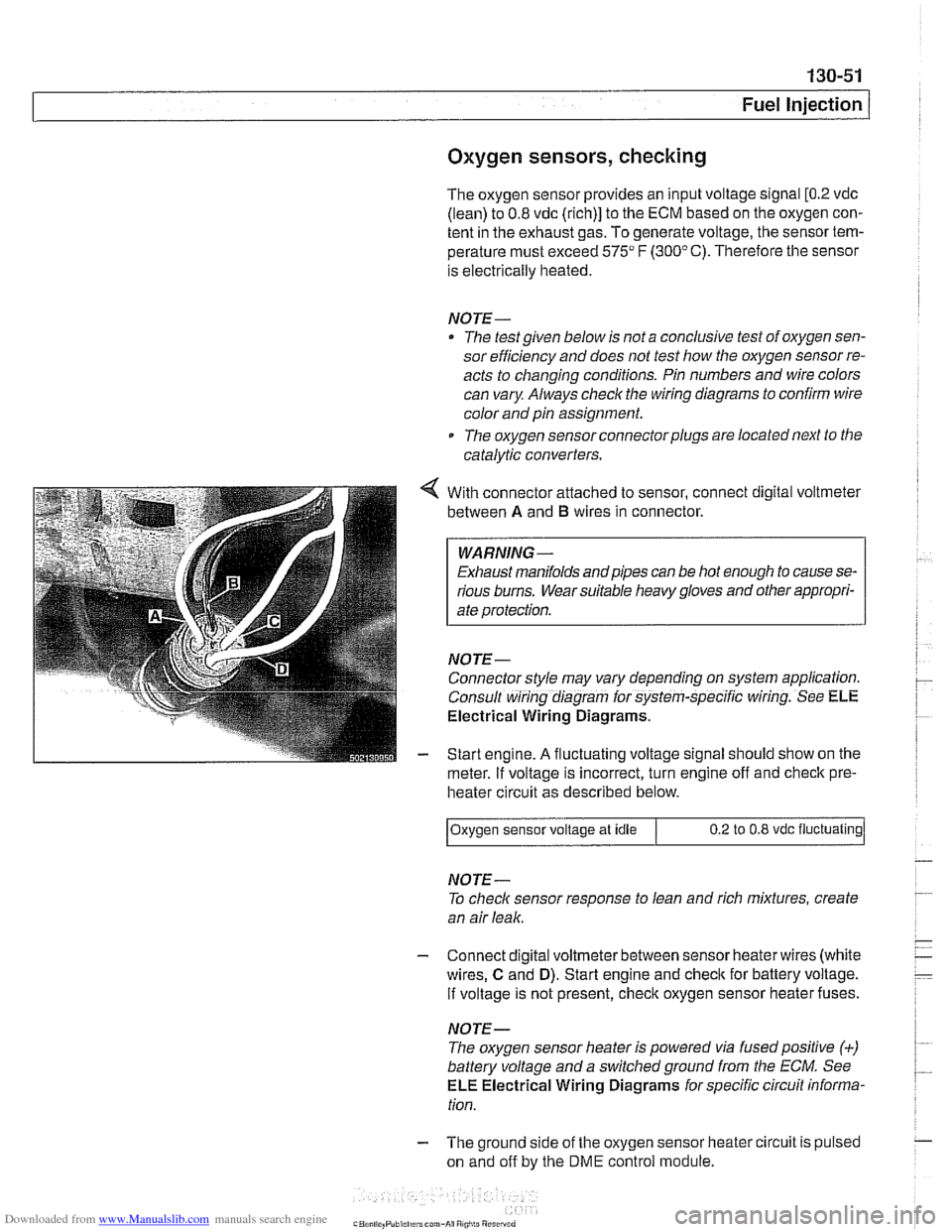
With connector attached to sensor, connect digital voltmeter
between
A and B wires in connector.
WARNING -
Exhaust manifolds andpipes can be hot enough to cause se-
rious burns. Wear suitable heavy gloves and other appropri-
ate protection.
NOJE-
Connector style may vary depending on system application.
Consult wiring diagram for system-specific wiring. See
ELE
Electrical Wiring Diagrams.
Start engine.
A fluctuating voltage signal should show on the
meter.
If voltage is incorrect, turn engine off and check pre-
heater circuit as described below.
NOJE-
To check sensor response to lean and rich mixtures, create
an air leak.
Oxygen sensor
voltage at idle
- Connect digital voltmeterbetween sensor heaterwires (white
wires,
C and D). Start engine and check for battery voltage.
If voltage is not present, check oxygen sensor heater fuses.
0.2 to 0.8 vdc fluctuating
NOJE-
The oxygen sensor heater is powered via fusedpositive (+)
battery voltage and a switchedground from the ECM. See
ELE Electrical Wiring Diagrams for specific circuit informa-
tion.
- The ground side of the oxygen sensor heater circuit is pulsed
on and off by the
DME control module.
Page 442 of 1002
Downloaded from www.Manualslib.com manuals search engine
.. .-
/Fuel lnjeciion
NOJE-
With engine oft disconnect harness connector and checlc
heating element resistance between white wires on the sen-
sor side of harness. If the element is electrically open (no
continuity), replace sensor.
- If oxygen sensor does not produce a fluctuating voltage and
preheater circuit is
OK, replace sensor.
NOJE-
If not already applied, coat oxygen sensor threads w~th anti-
seize compound before installat~on. Do not get the com-
pound on the sensor tip.
Tightening torque Oxygen sensor to exhaust system
55 Nm (41 ft-lb)
Fuel injectors, checking and replacing
The fuel iniectors are switched on and off (oaened and
closed)
by'the ECM. The injectors are connkcted to acom-
mon power source. A ground signal from the ECM is used to
open and close the injectors.
CA U JIOG
Use only a digital multimeter or an LED injector tester when
testing injectors or wiring. Use of an analog
VOM or incan-
descent test light may damaqe the engine controlmodule.
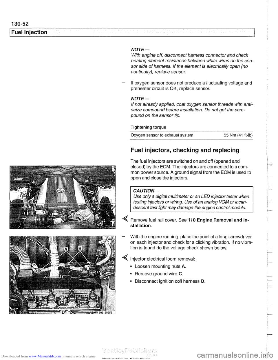
4 Remove fuel rail cover. See 110 Engine Removal and in-
stallation.
With the engine running, place the point of a long screwdriver
on each injector and check for a cliclting vibration.
If no vibra-
tion is found do the voltage
checit shown below.
Injector electrical loom removal:
- Loosen mounting nuts A.
Remove ground wire C.
Disconnect ignition coil harness D
Page 448 of 1002
Downloaded from www.Manualslib.com manuals search engine
Fuel Injection Evaporative fuel system pressure leak
diagnosis, overview
(M5.2.1 only)
1998 540i models are equipped with an evaporative fuel sys-
tem pressure leak diagnosis system. The main component of
this system is the leak diagnosis pump (LDP). The function of
the LDP is to pressurize the fuel tank and the evaporative
emission system for the purpose of detecting
leaks. This sys-
tem is capable of detecting a leak as small as 0.5 mm.
The LDP, located in the left rear wheel housing, is a unitized
component that contains the following:
Vacuum chamber. Pneumatic pump chamber.
DME activated vacuum solenoid
Reed switch (provides switched voltage
feedback signal to
ECM).
The vacuum supply line is in the wiring harness from the en-
gine compartment and runs down the driver's side of the vehi-
cle.
The canister vent valve is integrated into the LDP, which is
electrically controlled by the ECM. The canister vent valve is
opened to provide fresh air entry into the fuel system only dur-
ing purge operation.
- Purge operation characteristics:
Off idle through full throttle: purge valve opened by pulse
width modulated (PWM) control of the ECM. PWM duty cy-
cle varies by engine operating conditions
(e.g. warm idle,
purge valve opened slightly; cold
idleldecel with engine
temp
< 67" C, purge valve always closed).
Page 451 of 1002
Downloaded from www.Manualslib.com manuals search engine
-. -
Fuel Injection
I 68 1 / Not used
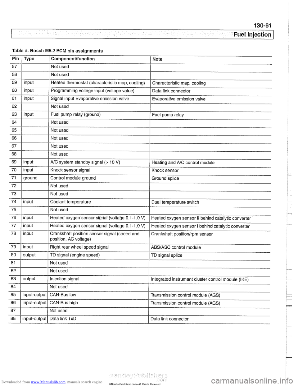
Table
d. Bosch
M5.2 ECM pin assignments
I I I
69 1 input I AIC system standby signal (> 10 V) 1 Heating and AIC control module
Pin
57
58
59
60
61
62
63
64
65 66
67
Type
input
input
input
input
I 70
72
73
74
Componentlfunction
Not used
Not used
Heated thermostat (characteristic map, cooling)
Programming voltage input (voltage
value)
Signal input Evaporative emission valve
Not used
Fuel pump relay (ground)
Not used
Not used
Not used
Not used
75
76
77
78
79
80
Note
Characteristic map, cooling
Data
llnlc connector
Evaporative emission valve
Fuel pump relay
71 1 ground I Control module ground I Ground splice
input
input
81
input input
input
input
output Not used
I
Knock sensor signal
Not used
Not used
Coolant temperature
82 1 I Not used
83
I I
Knock sensor
Dual temperature
swltch
Not used
Heated oxygen sensor signal (voltage
0.1-1.0 V)
Heated oxygen sensor
signal (voltage 0.1-1.0 V)
Crankshaft position sensor signal (speed and
position, AC voltage)
Right rear wheel speed signal
TD signal (engine speed)
85
I I I
Heated oxygen sensor II behind catalytic converter
Heated oxygen sensor
I behind catalytic converter
Cranitshaft positionlrpm sensor
ABSIASC control module
TD signal splice
84 1 / Not used 1
output
88
86
1 input-output 1 CAN-Bus high I Transmission conlrol module (AGS)
input-output
Injection signal
input-output Integrated instrument cluster control
module (IKE)
CAN-Bus low Transmission control module (AGS)
Data
linlc TxD Data link connector
Page 456 of 1002
Downloaded from www.Manualslib.com manuals search engine
Fuel Injection
When system faults are detected, a diagnostic trouble code
(DTC) is stored in the engine control module (ECM). The MIL
also illuminates
if an emissions-related fault is detected.
When faults arise, or
if the malfunction indicator lamp (MIL) is
illuminated, begin troubleshooting by connecting BMW ser-
vice tester
DISplus, MoDiC, GTl or equivalent scan tool. The
capabilities of OBD
II software has the potential to save hours
of diagnostic time and to help avoid incorrect component re-
placement and possible damage to system components.
CA UTIOI\C
The tests in this section may set fault codes (DTCs) in the
ECM and illuminate the MIL. After all testing is completed,
access and clear DTC fault memory using an OBD
I1 or
BMW compatible scan tool. See OBD On-Board Diag-
nostics.
. Only use a digital multimeter for electrical tests.
Relay positions can vary. Be sure to confirm relay posi-
tion by identifying the wiring in the
socket using the wir-
ing diagrams found in ELE Electrical Wiring
Diaqrams.
NOTE-
= OBD I1 fault memory (including an illuminated MIL) can
only be reset using the special scan tool. Removing the
connector from the ECM or disconnecting the battery will
not erase the fault memory.
0 The BMW-dedicated 20-pin diagnostic link connector
(DLC) is in the right rear of the engine compartment. The
20-pin DLC was eliminated on models after
6/2000.
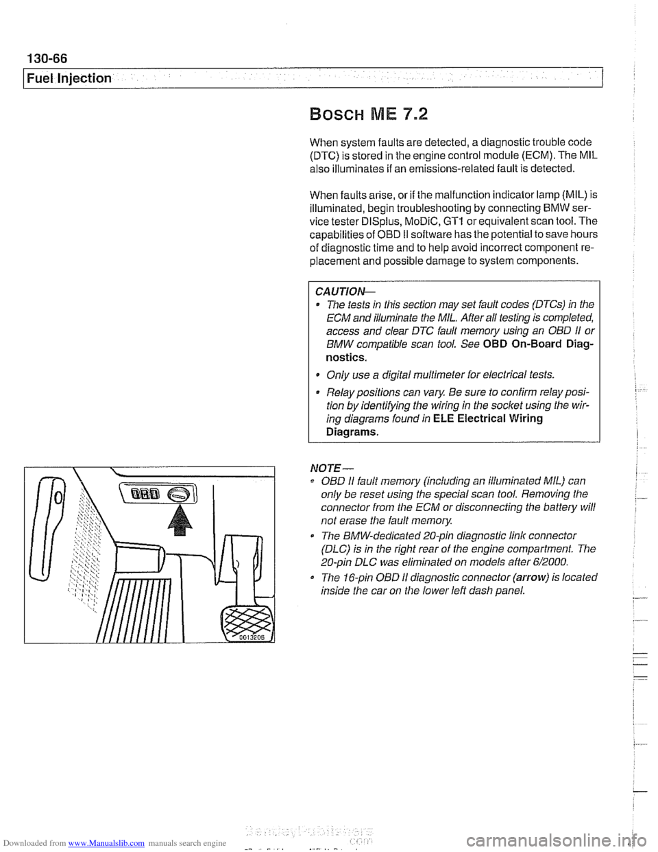
The 16-pin OBD I1 diagnostic connector (arrow) is located
inside the car on the lower left dash panel.
Page 457 of 1002
Downloaded from www.Manualslib.com manuals search engine
130-67
Fuel Injection /
ME 7.2 system overview
The Bosch ME 7.2 system is used on 1999 - 2002 540i mod-
els.
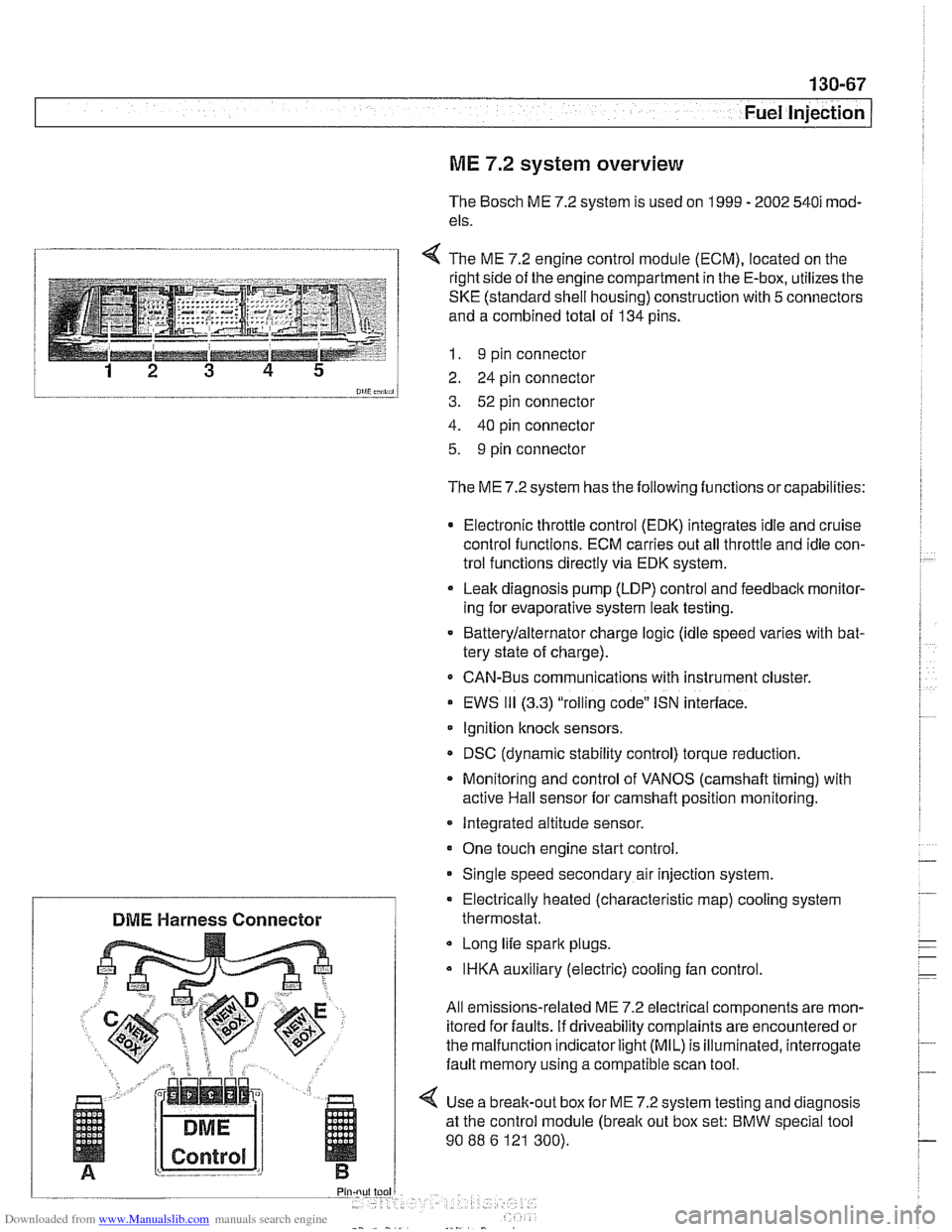
1 4 The ME 7.2 enaine control module (ECM). located on the
l and a combined total of 134 pins.
--__-- 1 I. 9 pin connector
12 3 4 5 2 24 pin connector
0lliC;nii, 3. 52 pin connector
4. 40 pin connector
5. 9 pin connector
The ME 7.2 system has the following functions or capabilities:
Electronic throttle control (EDK) integrates idle and cruise
control functions. ECM carries out all throttle and idle con-
trol functions directly via EDK system.
Leak diagnosis pump
(LDP) control and feedback monitor-
ing for evaporative system leak testing.
Batterylalternator charge logic (idle speed varies with bat-
tery state of charge).
CAN-Bus communications with instrument cluster.
EWS
111 (3.3) "rolling code" ISN interface.
Ignition
knock sensors.
DSC (dynamic stability control) torque reduction.
Monitoring and control of VANOS
(camshaft timing) with
active Hail sensor for camshaft position monitoring.
Integrated altitude sensor.
One touch engine start control
Single speed secondary air injection system.
Long life spark plugs.
IHKA auxiliary (electric) cooling fan control.
All emissions-related ME 7.2 electrical components are mon-
itored for faults. if driveability complaints are encountered or
the malfunction indicator
light (MIL) is illuminated, interrogate
fault memory using a compatible scan tool.
4 Use a break-out box for ME 7.2 system testing and diagnosis
at the control module
(break out box set: BMW special tool
90
88 6 121 300).
Electrically heated (characteristic
map) cooling system
DME Harness Connector thermostat.
Page 458 of 1002
Downloaded from www.Manualslib.com manuals search engine
130-68
Fuel Injection
0
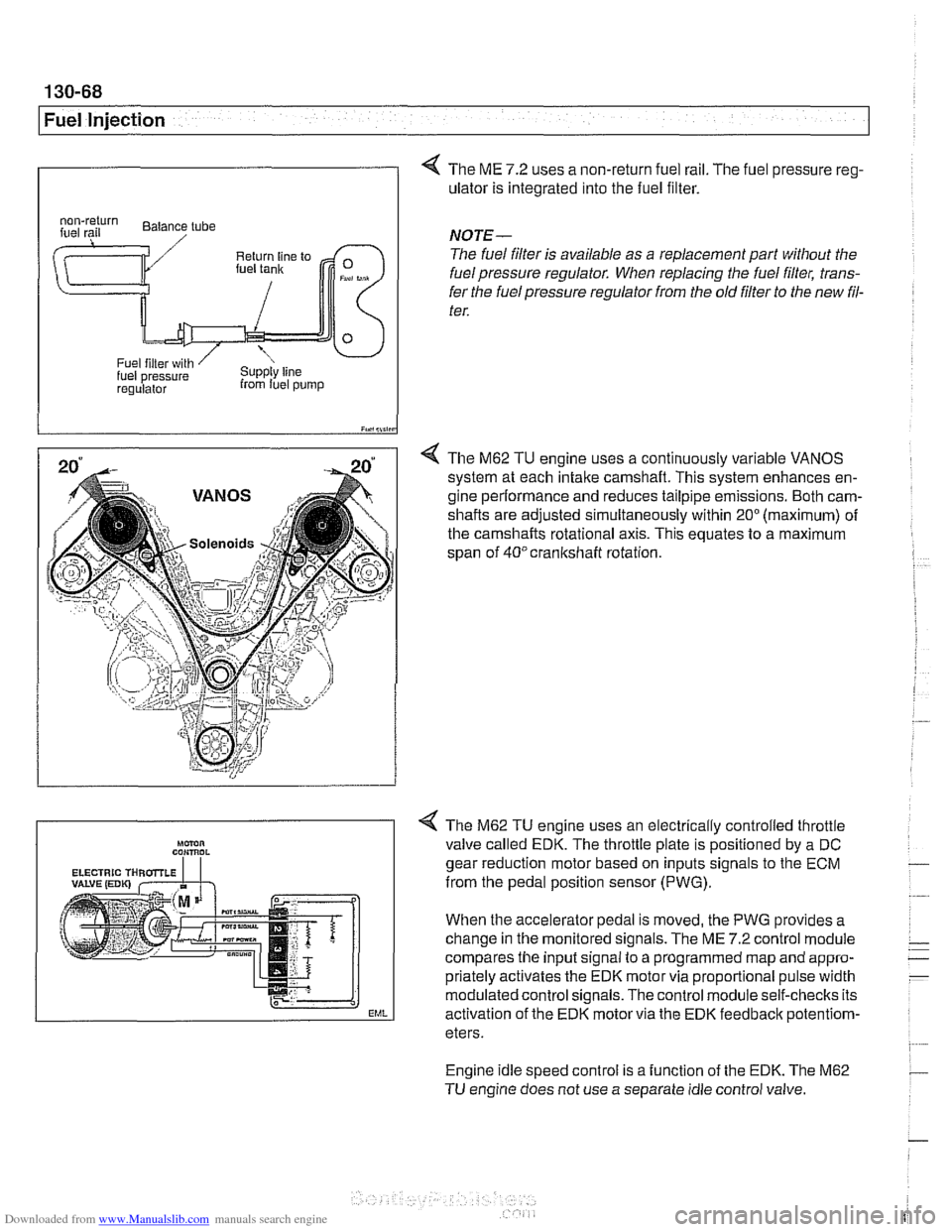
4 The ME 7.2 uses a non-return fuel rail. The fuel pressure reg-
ulator is integrated into the fuel filter.
I iY.,lii,in
4 The M62 TU engine uses a continuously variable VANOS
system at each intake camshaft. This system enhances en-
gine performance and reduces tailpipe emissions. Both cam-
shafts are adjusted simultaneously within
20" (maximum) of
the camshafts rotational axis. This equates to a maximum
span of
40°crankshaft rotation.
regulalor from luel pump
NOTE-
The fuel filter is available as a replacement part without the
fuel pressure regulator. When replacing the fuel filter, trans-
fer the fuel pressure regulator from the old
filter to the new fil-
ter.
Engine idle speed control is a function of the EDK. The M62
TU engine does not use a separate idle control valve.
Mmn CON,ROL
EML
< The M62 TU engine uses an electrically controlled throttle
valve called EDK. The throttle plate is positioned by a DC
gear reduction motor based on inputs signals to the ECM
from the pedal position sensor (PWG).
When the accelerator pedal is moved, the PWG provides a
change in the monitored signals. The ME
7.2 control module
compares the input signal to a programmed map and appro-
priately activates the EDK motor via proportional pulse width
modulated control signals. The control module self-checks its
activation of the EDK motor via the EDK feedbaclc
potentiom-
eters.
Page 459 of 1002
Downloaded from www.Manualslib.com manuals search engine
--
Fuel Injection I
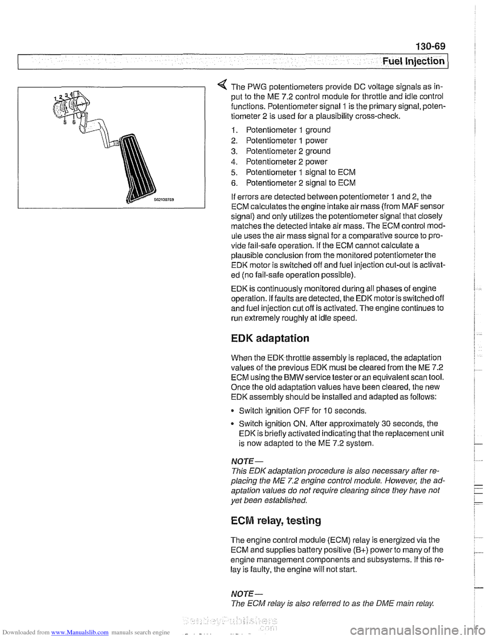
The PWG potentiometers provide DC voltage signals as in-
put to the ME 7.2 control module for throttle and idle control
functions. Potentiometer signal
1 is the primary signal, poten-
tiometer 2 is used for a plausibility cross-check.
1. Potentiometer 1 ground
2. Potentiometer
1 power
3. Potentiometer 2 ground
4. Potentiometer 2 power
5. Potentiometer 1 signal to ECM
6. Potentiometer 2 signal to ECM
If errors are detected between potentiometer
1 and 2, the
ECM calculates the engine intake air mass (from
MAFsensor
signal) and only utilizes the potentiometer signal that closely
matches the detected
intake air mass. The ECM control mod-
ule uses the air mass signal for a comparative source to pro-
vide fail-safe operation.
If the ECM cannot calculate a
plausible conclusion from the monitored potentiometerthe
EDK motor is switched off and fuel injection cut-out is activat-
ed (no fail-safe operation possible).
EDK is continuously monitored during all phases of engine
operation. If faults are detected, the EDK motor is switched off
and fuel injection cut off is activated. The engine continues to
run extremely roughly at idle speed.
EDK adaptation
When the EDK throttle assembly is replaced, the adaptation
values of the previous EDK must be cleared from the ME 7.2
ECM using the BMW service testeroran equivalentscan tool.
Once the old adaptation values have been cleared, the new
EDK assembly should be installed and adapted as follows:
0 Switch ignition OFF for 10 seconds.
* Switch ignition ON. Afler approximately 30 seconds, the
EDK is briefly activated indicating that the replacement unit
is now adapted to the ME 7.2 system.
NOTE-
This EDK adaptation procedure is also necessary after re-
placing the
ME 7.2 engine control module. However, the ad-
aptation values do not require clearing since they have not
yet been established.
ECM relay, testing
The engine control module (ECM) relay is energized via the
ECM and supplies battery positive
(B+) power to many of the
engine management components and subsystems. If this re-
lay is faulty, the engine will not start.
NOTE-
The ECM relay is also referred to as the DME main relay
Page 464 of 1002
Downloaded from www.Manualslib.com manuals search engine
130-74
I Fuel Injection
Evaporative system pressure leak
diagnosis, overview
The M62 TU engine is equipped wlth an evaporative fuel sys-
tem pressure leak diagnosis system. The main component of
this system is the leakdiagnosis pump (LDP). The function of
the LDP is to pressurize the fuel tank and the evaporative
emission system for the purpose of detecting leaks.
This system iscapable of detecting a
lealcas small as0.5 mm.
The LDP, located in the left rear wheel housing, contains the
following:
Vacuum chamber. Pneumatic pump chamber
DME activated vacuum solenoid
Reed switch (provides switched voltage
feedback signal to
DME).
The vacuum supply line is in the wiring harness from the en-
gine compartment and runs down the driver's side of the vehi-
cle.
The canister vent valve is
~ntegrated into the LDP, which IS
electrically controlled by the ECM. The canister vent valve is
opened to provide fresh air entry into the fuel system only dur-
ing purge operation.
- Purge operation characteristics:
Off idle through full throttle: purge valve opened by pulse
width modulated (PWM) control of the ECM. PWM duty cy-
cle varies by engine operating conditions
(e.g. warm idle,
purge valve opened slightly; cold
idleldecel with engine
temp
< 67" C. purge valve always closed).
Page 465 of 1002
Downloaded from www.Manualslib.com manuals search engine
130-75
Fuel Injection
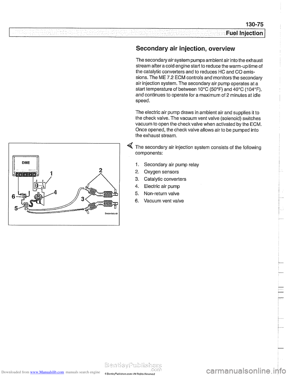
Secondary air injection, overview
The secondary air system pumps ambient air into the exhaust
stream afteracoid engine start to reduce the warm-up time of
the catalytic converters and to reduces HC and CO emis-
sions. The ME
7.2 ECM controls and monitors the secondary
air injection system. The secondary air pump operates at a
starttemperature of between 10°C
(50°F) and 40°C (104°F).
and continues to operate for a maximum of
2 minutes at idle
speed.
The electric air pump draws in ambient air and supplies it to
the
checlc valve. The vacuum vent valve (solenoid) switches
vacuum to open the
checlc valve when activated by the ECM.
Once opened, the checlc
valve allows air to be pumped into
the exhaust stream.
4 The secondary air injection system consists of the following
components:
1. Secondary air pump relay
2. Oxygen sensors
3. Catalytic converters
4. Electric air pump
5. Non-return valve
6. Vacuum vent valve