Codes BMW 528i 1998 E39 Owner's Manual
[x] Cancel search | Manufacturer: BMW, Model Year: 1998, Model line: 528i, Model: BMW 528i 1998 E39Pages: 1002
Page 436 of 1002
Downloaded from www.Manualslib.com manuals search engine
130-46
Fuel Injection
When system faults are detected, a diagnostic trouble code
(DTC) is stored in the engine control module (ECM). The MIL
also illuminates if an emissions-related fault is detected.
When faults arise, or
if the malfunction indicator lamp (MIL) is
illuminated, begin troubleshooting by connecting BMW ser-
vice tester
DISplus. MoDiC, GTI or equivalent scan tool. The
capabilities of
OED II software has the potential to save hours
of diagnostic time and to help avoid incorrect component re-
placement and possible damage to system components.
CA UTIOiU-
The tests in this section may set fault codes (DTCs) in the
ECM and illuminate the MIL. After ail testing is completed,
access and clear DTC fault
memory using an OED I/ or
BMW compatible scan tool. See OBD On-Board Diag-
nostics.
Only use a digital
multimeter for electrical tests.
Relay positions can vary. Be sure to confirm relay
posi-
. tion by identifying the wiring in the socket using the wir-
ing diagrams-found in ~~~~lectrical Wiring
Diagrams.
NOTE-
OED I1 fault memory (including an illuminated MIL) can
only be reset
using~the special scan tool. Removing the
connector from the ECM or disconnecting the battery will
not erase the fault
memory.
The BMW-dedicated 20-pin diagnostic link connector
(DLC) is in the right rear of the engine compartment.
The 16-pin OBD
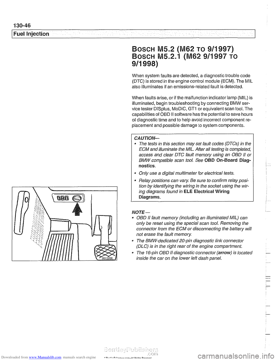
I1 diagnostic connector (arrow) is located
inside the car on
the lower left dash panel.
Page 447 of 1002
Downloaded from www.Manualslib.com manuals search engine
Fuel Injection
Intake air temperature
([AT) sensor,
testing and replacing
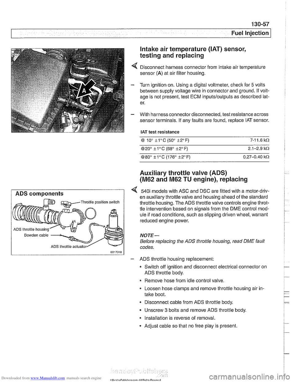
Disconnect harness connector from intake air temperature
sensor
(A) at air filter housing.
Turn ignition on. Using a digital voltmeter, check for
5 volts
between supply voltage wire in connector and ground.
If volt-
age is not present, test ECM
inputs/outputs as described lat-
er.
With harness connector disconnected, test resistance across
sensor terminals. If any faults are found, replace IAT sensor.
IAT test resistance
0 lV *lac (50" i-2°F) 7-1 1.6 k.0.
020' kl°C (68' 322°F) 2.1-2.9 it.0.
080" ?lac (176" i-2°F) 0.27-0.40 itn
Auxiliary throttle valve (ADS)
(M62 and M62 TU engine), replacing
ADS components 540i models with ASC and DSC are fitted with a motor-driv-
en auxiliary throttle valve and housing ahead of the standard Throttle position switch throttle housing. The ADS throttle valve controls engine throt-
tle intervention based on signals from the DME control mod-
ule if road conditions, such as slipping driven wheel, warrant
reduced engine power.
ADS throttle housing
Bowden cable NOTE-
Before replacing the ADS throttle housing, read DME fault
ADS lhroltle actualor codes.
- ADS throttle housing replacement:
Switch off ignition and disconnect electrical connector on
ADS throttle body.
Remove hose from idle control valve.
Loosen hose clamps and remove throttle housing air in-
take boot.
Disconnect cable from ADS throttle body.
- Unscrew 3 bolts and remove ADS throttle body.
Installation is reverse of removal.
- Adjust cable so that no free play is present.
Page 456 of 1002
Downloaded from www.Manualslib.com manuals search engine
Fuel Injection
When system faults are detected, a diagnostic trouble code
(DTC) is stored in the engine control module (ECM). The MIL
also illuminates
if an emissions-related fault is detected.
When faults arise, or
if the malfunction indicator lamp (MIL) is
illuminated, begin troubleshooting by connecting BMW ser-
vice tester
DISplus, MoDiC, GTl or equivalent scan tool. The
capabilities of OBD
II software has the potential to save hours
of diagnostic time and to help avoid incorrect component re-
placement and possible damage to system components.
CA UTIOI\C
The tests in this section may set fault codes (DTCs) in the
ECM and illuminate the MIL. After all testing is completed,
access and clear DTC fault memory using an OBD
I1 or
BMW compatible scan tool. See OBD On-Board Diag-
nostics.
. Only use a digital multimeter for electrical tests.
Relay positions can vary. Be sure to confirm relay posi-
tion by identifying the wiring in the
socket using the wir-
ing diagrams found in ELE Electrical Wiring
Diaqrams.
NOTE-
= OBD I1 fault memory (including an illuminated MIL) can
only be reset using the special scan tool. Removing the
connector from the ECM or disconnecting the battery will
not erase the fault memory.
0 The BMW-dedicated 20-pin diagnostic link connector
(DLC) is in the right rear of the engine compartment. The
20-pin DLC was eliminated on models after
6/2000.
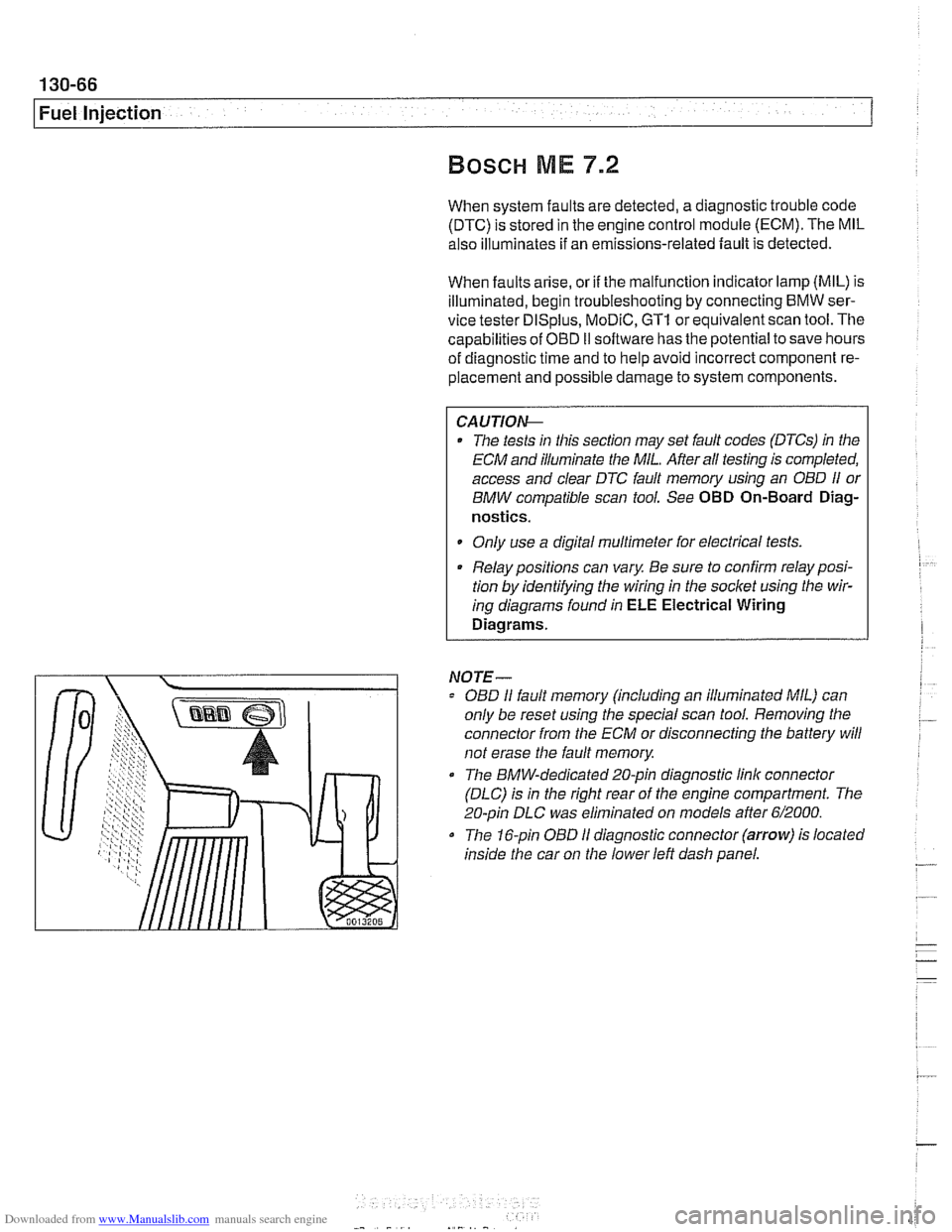
The 16-pin OBD I1 diagnostic connector (arrow) is located
inside the car on the lower left dash panel.
Page 474 of 1002
Downloaded from www.Manualslib.com manuals search engine
Fuel Tank and Fuel Pump
Evaporative system troubleshooting
- Start by accessing diagnostic trouble codes (DTCs) using a
BMW or BMW compatible aftermarket scan tool.
For purposes of OBD
II emissions compliance, the DME
system sets a diagnostic trouble code (DTC) when it de-
tects a leak that is equal or larger than minimum
lealc
sensed by system.
Malfunction Indicator Light (MIL) is illuminated upon sec-
ond recurrence of fault. See OBD On-Board Diagnostics.
- When leak testing, observe following conditions to obtain
plausible results:
Fuel tank
'1, to 'I., full.
0 Vehicle parked for at least 2 hours to allow fuel to reach
room temperature.
Ideal fuel temperature is 10"- 20°C
(50"
- 68" F).
Do not refuel immediately before
lealc test.
- If a leak is detected, check the following areas:
* Fuel filter cap (leaking or off).
Fuel tank ventilation lines leaking at fuel
tank or activated
carbon canister.
i
Tank ventilation valve leaking (in engine compartment).
Fuel level
sensorlfuel pump cap leaking.
Evaporative system component replacement is covered later
in
th~s group in Fuel Tank and Fuel Lines.
Page 503 of 1002
Downloaded from www.Manualslib.com manuals search engine
Warnings and cautions
Obse~e the following warnings and cautions when worlting
on the cooling system.
WARNING -
. At normal operating temperature the cooling system is
pressurized. Allow the system to cool as long as possible
before opening (a minimum of one hour), then release the
cap slowly to allow safe release ofpressure.
a Releasing the coolant system pressure lowers the cool-
ant boilingpoint and the coolant may boil suddenly. Use
1 heavy and wear eye and face protection to
guard against scalding.
Use extreme care when draining and disposing of en-
gine coolant. Coolant is poisonous and lethal to hu-
mans andpets. Pets are attracted to coolant because
of its sweet smell and taste. Seek medical attention im-
mediately if coolant is ingested.
CAUTIOG
Avoid adding cold water to the coolant while the engine is
hot or overheated. If it is necessary to add coolant to a
hol
system, do so only with the engine running and coolanl
pump turning.
To avoid excess silicate gel precipitation in the cooling
system and loss of cooling capacity, use BMW coolant
or equivalent low silicate antifreeze.
a If oil enters the cooling system, the radiator, expansion
tank and heating circuit must be flushed with cleaning
agent. BMW recommends removal of the radiator and
expansion
tank to flush.
When
worlcing on the cooling system, cover the alter-
nator to protect it against coolant drips.
Prior to disconnecting the battery, read the battery dis-
connection cautions given in
001 General Warnings
and Cautions.
Begin the diagnosis of cooling system problems with a thor-
ough visual inspection.
If no visual faults are found, it is rec-
ommend that the engine control module (ECM) fault memory
be checked for stored diagnostic trouble codes
(DTCs) using
BMW scan tool
DlSplus or equivalent.
Page 513 of 1002
Downloaded from www.Manualslib.com manuals search engine
Radiator and Cooling systeml
Tightening torques
Block drain plug to block 25 Nm
(18
it-lb)
Coolant hose clamp (32 - 48 2.
5 Nm (22 in-lb)
mm hose diameter)
Radiator drain plug to radiator
2-3Nm(l8-27in-lb)
Thermostat housing to cylinder
head 10 Nm (89 in-lb)
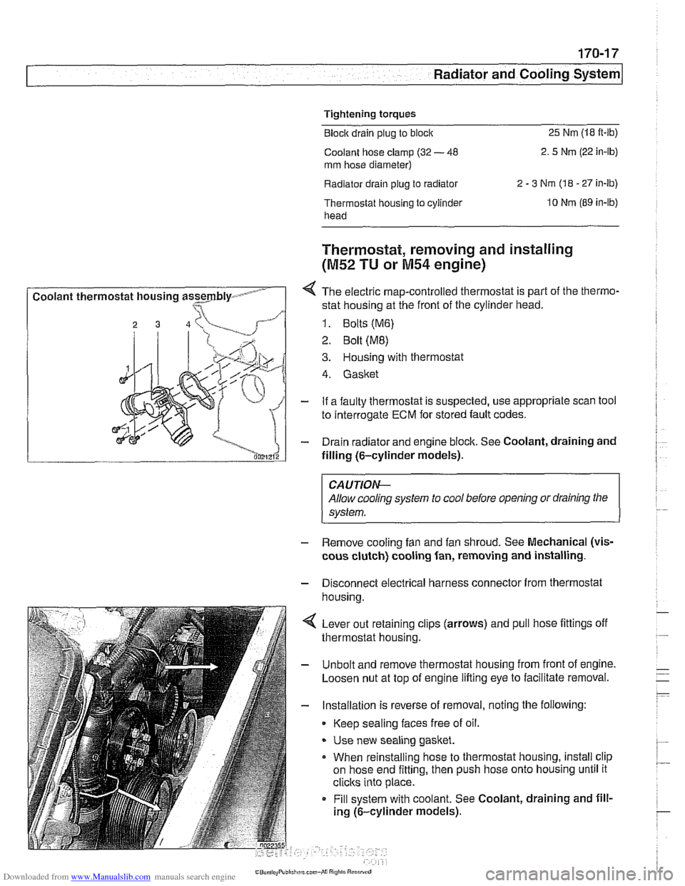
I Coolant thermostat housing assmbly- - I
Thermostat, removing and installing
(M52 TU or M54 engine)
4 The electric map-controlled thermostat is part of the thermo-
stat housing at the front of the cylinder head.
1. Bolts (M6)
2 Bolt (ME)
3. Housing with thermostat
4. Gasket
- If a faulty thermostat is suspected, use appropriate scan tool
to interrogate
ECM for stored fault codes.
- Drain radiator and engine block. See Coolant, draining and
filling (6-cylinder models).
CAUTION-
Allow cooling system to cool before opening or draining the
system.
- Remove cooling fan and fan shroud. See Mechanical (vis-
cous clutch) cooling fan, removing and installing.
- Disconnect electrical harness connector from thermostat
housina.
4 Lever out retaining clips (arrows) and pull hose fittings off
thermostat housing.
- Unbolt and remove thermostat housing from front of engine.
Loosen nut at top of engine lifting eye to facilitate removal.
- Installation is reverse of removal, noting the following:
Keep sealing faces free of oil.
* Use new sealing gasket.
When reinstalling hose to thermostat housing, install clip
on hose end fitting, then push hose onto housing until it
clicks into place.
Fill system with coolant. See Coolant, draining and fill-
ing (6-cylinder models).
Page 514 of 1002
Downloaded from www.Manualslib.com manuals search engine
Tightening torques Block drain plug to block
25 Nm (18 ft-lb)
Radiator drain plug to radiator 2 - 3 Nm (18 - 27 in-lb)
Thermostat housing to
cylinder head 10 Nm (89 in-lb)
Thermostat, removing and installing
(V-8 models)
The electrically-heated thermostat is an integral parl of the
thermostat housing. The operation of the thermostat is moni-
tored by the engine control module (ECM).
- If a faulty thermostat is suspected, use appropriate scan tool
to interrogate ECM for stored fault codes.
- Drain radiator and engine block. See Coolant, draining and
filling
(V-8 models).
WARNING -
Allow cooling system to cool before opening or draining the
system.
- Disconnect mass air flow (MAF) sensor electrical harness
connector. Remove air intake duct together with MAF sensor.
- Remove mechanical cooltng fan and fan shroud. See Me-
chanical (viscous clutch) cooling fan, removing and
in-
stalling.
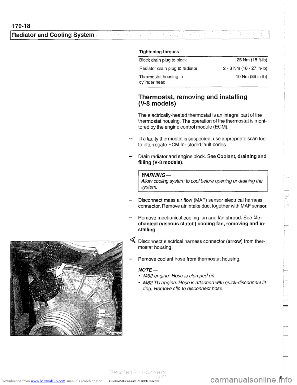
Disconnect electrical harness connector (arrow) from ther-
mostat housing.
Remove coolant hose from thermostat housing.
NOTE-
M62 engine: Hose is clamped on.
M62 TU engine: Hose is attached with quick-disconnect fit.
ting. Remove clip to disconnect hose.
Page 531 of 1002
Downloaded from www.Manualslib.com manuals search engine
-- -
Exhaust System
Oxygen sensors (precatalyst), replacing
(M52 TU and M54)
The precatalyst oxygen sensors are installed at the top of the
exhaust manifolds.
WARNING-
Allow components to cool before servicing.
- Using BMW scan tool DlSplus (Diagnostic Information Sys-
tem) or equivalent, read out and clear ECM fault codes.
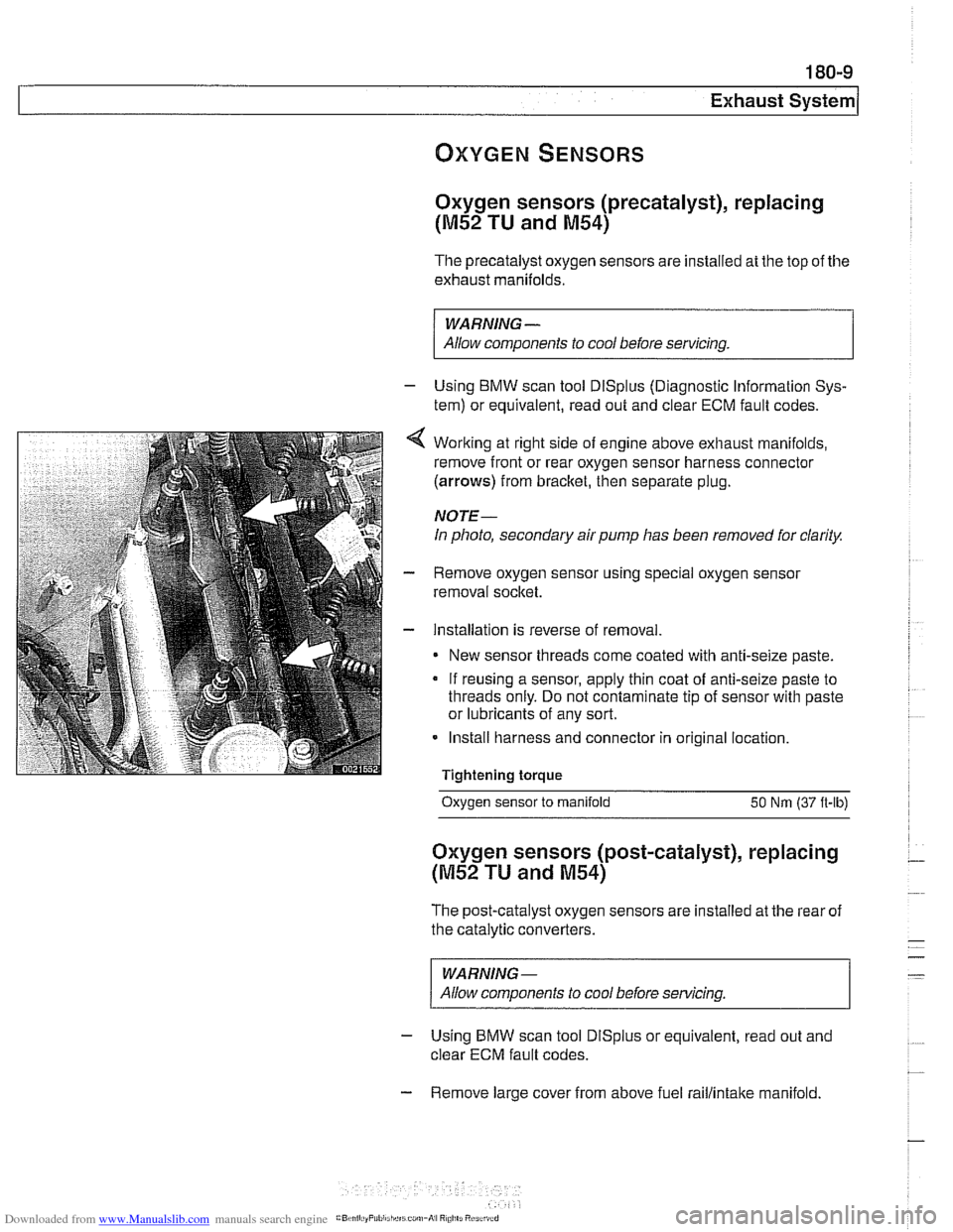
Working at right side of engine above exhaust manifolds,
remove front or rear oxygen sensor harness connector
(arrows) from bracket, then separate plug.
NOTE-
In photo, secondary air pump has been removed for clarity.
Remove oxygen sensor using special oxygen sensor
removal socket.
Installation is reverse of removal
New sensor threads come coated with anti-seize paste.
If reusing a sensor, apply thin coat of anti-seize paste to
threads only. Do not contaminate tip of sensor with paste
or lubricants of any sort.
Install harness and connector in original location.
Tightening torque
- -.
Oxygen sensor to manifold 50 Nm (37 ft-lb)
Oxygen sensors (post-catalyst), replacing
(M52 TU and M54)
The post-catalyst oxygen sensors are installed at the rear of
the catalytic converters.
WARNING-
Allow components to cool before servicing
- Using BMW scan tool DlSplus or equivalent, read out and
clear ECM fault codes.
- Remove large cover from above fuel raillintake manifold.
Page 532 of 1002
Downloaded from www.Manualslib.com manuals search engine
Exhaust System
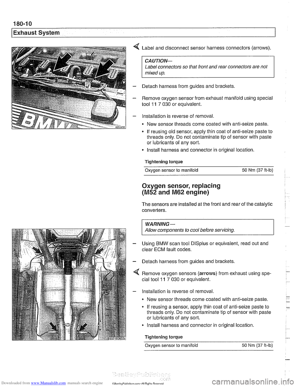
Label and disconnect sensor harness connectors (arrows).
CAUTlOI\C
Label connectors so that front and rear connectors are not
mixed up.
- Detach harness from guides and brackets.
- Remove oxygen sensor from exhaust manifold using special
tool
11 7 030 or equivalent.
- Installation is reverse of removal
New sensor threads come coated with anti-seize paste.
If reusing old sensor, apply thin coat of anti-seize paste to
threads only. Do not contaminate tip of sensor with paste
or lubricants of any sort.
Install harness and connector in original location.
Tightening torque
Oxygen sensor to manifold 50 Nm (37 ft-lb)
Oxygen sensor, replacing
(M52 and M62 engine)
The sensors are installed at the front and rear of the catalytic
converters.
I WARNING- I
I Allow components to cool before servicing. I
Using BMW scan tool DlSplus or equivalent, read out and
clear
ECM fault codes.
Detach harness from guides and brackets.
Remove oxygen sensors (arrows) from exhaust using spe-
cial tool
ll 7 030 or equivalent.
Installation is reverse of removal
New sensor threads come coated with anti-seize paste.
If reusing a sensor, apply thin coat of anti-seize paste to
threads only. Do not contaminate tip of sensor with paste
or lubricants of any sort.
Install harness and connector in original location.
Tightening torque
Oxvaen sensor to manifold 50 Nm (37 it-lb)
Page 589 of 1002
Downloaded from www.Manualslib.com manuals search engine
- .- -
Automatic Transmission
Electronics are used to control the operation of these auto-
matic transmissions. Steptronic transmission functions are
also programmed into the transmission control module
(TCM). The TCM monitors transmission operation for faults
and alerts the driver by illuminating the transmission fault indi-
cator on the instrument panel. Diagnostic trouble codes
(DTCs) stored in the TCM may be downloaded and interpret-
ed by trained technicians using special BMW diagnostic
equipment.
Some minor automatic transmission problems can be cor-
rected by changing the automatic transmission fluid (ATF)
and filter. Begin by checking ATF level and condition.
Checlc
to see if the fluid is dirty or has a burned odor indicating over-
heated fluid. The burned odor may be the results of burned
discs in theclutch paclts. The friction material from the burned
disc can clog valve body passages.
NOTE-
The E39 automatic transmission is not equipped with a dip-
stick.
Checking the ATF level must be done while monitoring
the ATF temperature with the engine idling. The
BMW dealer
is equipped with the special equipment to make this check.