Codes BMW 528i 1998 E39 Owner's Guide
[x] Cancel search | Manufacturer: BMW, Model Year: 1998, Model line: 528i, Model: BMW 528i 1998 E39Pages: 1002
Page 777 of 1002
Downloaded from www.Manualslib.com manuals search engine
340-1 5
Brakes
- Remainder of installation is reverse of removal.
- Clean brake caliper mounting bolts (7 mm Allen). Replace
ones which are not in perfect condition. Do not grease.
Top up brake fluid to MAX marking.
- Before driving car, pump bralte pedal several times so that
brake pads contact brake rotors.
Check that brake fluid level is correct. Top up if necessary.
Hold ignition key for at least
30 seconds in accessory po-
sition without starting engine. This clears any fault codes in
memory and turns off brake pad warning light.
Tightening torques Brake caliper to pad carrier
(7 mm Allen)
Front caliper
30 Nm (22 It-lb)
- Rear caliper 28 Nm (21 It-lb)
Road wheel to hub
120i 10 Nm (89i7 ft-lb)
Brake rotors, removing and installing
- Raise car and remove wheels
WARNING-
Male sure that the car is firmly supported on jack stands de-
signed for the purpose. Place jack stands beneath structural
chassis points. Do not place jack stands under suspension
parts.
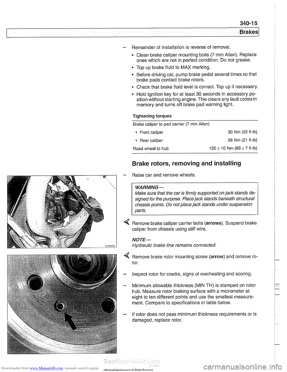
Remove brake caliper carrier bolts (arrows). Suspend brake
caliper from chassis using stiff wire.
NOTE-
Hydraulic brake line remains connected.
4 Remove bralte rotor mounting screw (arrow) and remove ro-
tor.
- Inspect rotor for cracks, signs of overheating and scoring.
- Minimum allowable thickness (MIN TH) is stamped on rotor
hub. Measure rotor braking surface with a micrometer at
eight to ten different points and use the smallest measure-
ment. Compare to specifications in table below.
- If rotor does not pass minimum thickness requirements or is
damaged, replace rotor.
Page 793 of 1002
Downloaded from www.Manualslib.com manuals search engine
340-31
Brakes
ABS 1 traction electronic control module
(1 997 -1 998 models)
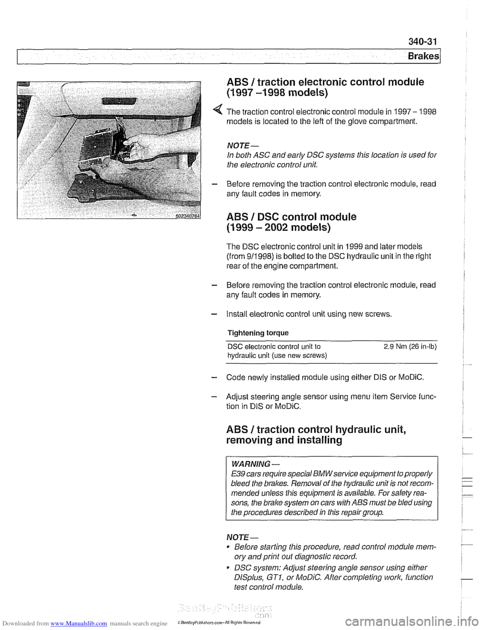
4 The traction control electronic control module in 1997- 1998
models is located to the left of the glove compartment.
NOTE-
In both ASC and early DSC systems this location is used for
the electronic control unit.
- Before removing the traction control electronic module, read
any fault codes in memory.
ABS I DSC control module
(1 999 - 2002 models)
The DSC electronic control unit in 1999 and later models
(from 911998) is bolted to the DSC hydraulic unit in the right
rear of the engine compartment.
- Before removing the traction control electronic module, read
any fault codes in memory.
- Install electronic control unit using new screws.
Tightening torque
DSC electronic control unit to 2.9 Nrn (26 in-lb)
hydraulic
unit (use new screws)
- Code newly installed module using either DIS or MoDiC.
- Adjust steering angle sensor using menu item Service func-
tion in
DIS or MoDiC.
ABS I traction control hydraulic unit,
removing and installing
WARNING -
E39 cars require special BMWsewice equipment to properly
bleed the brakes. Removal of the hydraulic unit is not recom-
mended unless this equipment is available. For safety rea-
sons, the
brake system on cars with ABS must be bled using
the procedures described in this repair group.
NOTE-
Before starting this procedure, read control module mem-
ory and print
out diagnostic record.
DSC system: Adjust steering angle sensor using
either
DISplus, GTI, or MoDiC. After completing work, function
test control module.
Page 950 of 1002
Downloaded from www.Manualslib.com manuals search engine
721 -2
l~irba~ System (SRS)
This repair group covers airbag components and replace-
ment.
Airbag system repairand fault diagnosis is not covered.
Diagnostics, component testing, and
airbag system repair
should be carried out by trained BMW service technicians.
Individual
airbag system components can only be tested elec-
tronically when installed in the car. BMW service testers
DIS
or MoDiC or equivalent must be used for diagnostic work.
WARNING-
Special test equipment is required to retrieve airbag fault
codes, diagnose system faults, and
reseffturn off the air-
bag indicator light. The indicator light will remain on until
any problem has been corrected and the fault memory has
been cleared.
Airbags are part of the BMW Multiple Restraint System
(MRS). Three versions of MRS are available in E39 models.
Multiple Restraint Systems
MRS and MRS II include the following restraint components:
311 996-811 997
911
997-311 999
311 999-2002
Driver and passenger front
airbags (MRSIMRS II)
MRS
MRS
II
MRS Ill
Passenger front two-stage airbag (cars manufactured
from
911998).
The seat occupancy sensor (SBE) is used for detection of
a passenger in the right front seat. MRS uses the SBE in-
put to determine seat belt tensioner
and/or front airbag de-
ployment thresholds.
Side impact
airbag for driver and front passenger
(MRSIMRS II)
Leftlright side impact crash sensors (MRSIMRS 11)
Side impact airbag for rear passenger (MRS II) (optional)
Head Protection System (HPS) for driver and front passen-
ger (MRS
II)
Battery Safety Terminal - BST (MRS II)
Hall Sensor seat belt switches (MRS II)
Front pyrotechnic seat belt tensioners
Fuel pump cut off message
Page 961 of 1002
Downloaded from www.Manualslib.com manuals search engine
OBD On-Board Diagnostics
I I
General ........................... OBD-1 Diaqnostic Trouble Codes (DTCs) . . OBD-9
On-Board Diagnostics (OBD I!) ..... OBD-I
Malfunction Indicator Light (MIL)
........ OBD-2
Scan tools and scan tool display.
........ OBD-3
Diagnostic monitors
.................. OED-4
Drive cycle
......................... OED-6
Readiness codes
.................... OBD-6
Diagnostic trouble codes
(DTCs) ........ OBD-7
-
Automatic transmission diagnostic
trouble codes
....................... OBD-9
Engine diagnostic trouble
codes: M52 engine.
................. OED-13
Engine diagnostic trouble
codes: M54 engine.
................. OBD-17
Engine diagnostic trouble
codes: M62 engine.
................. OBD-24
This chapter outlines the fundamentals and equipment
requirements of On-Board Diagnostics
I1 (OBD 11) standards
as they apply to BMW vehicles. Also covered here is a listing
of BMW and OBD
I1 diagnostic trouble codes (DTCs).
ON-BOARD DIAGNOSTICS (QBD !I)
OBD II standards were developed by the SAE (Society of
Automotive Engineers) and CARB (California Air Resources
Board).
OED I1 is the second generation of on-board self-
diagnostic equipment requirements. These standards were
originally mandated for California vehicles. Since
1996 they
have been applied
toall passengervehicles sold in the United
States.
On-board diagnostic capabilities are incorporated into the
hardware and soflwareof the enginecontrol module
(ECM) to
monitor virtually every component that can affect vehicle
emissions. The
OED I1 system works to ensure that
emissions remain as clean as possible over the life of the
vehicle.
Each emission-influencing component is checked by a
diagnostic routine (called a monitor) to verify that it is
functioning properly.
If a problem or malfunction is detected,
the
diagnostic executive built into the OBD I1 system
illuminates a malfunction indicator light (MIL) on the
instrument panel.
The OBD
I1 system also stores diagnostic trouble codes
(DTCs) about the detected malfunction in the ECM so that a
repair technician can accurately find and fix the problem.
Page 963 of 1002
Downloaded from www.Manualslib.com manuals search engine
OBD-3
On-Board
~iactnosticsl
Additional MIL information:
A fault code is stored within the ECM upon the first
occurrence of a fault in the system being checlted.
Two complete consecutive drive cycles with the iault
present illuminate the MIL. The exception to the two-fault
requirement is a catalyst-damaging fault, which illuminates
the MIL immediately.
If the second drive cycle was not complete and the fault
was not checked, the ECM counts the third drive cycle as
the next consecutive drive cycle. The MIL illuminates
if the
system is checked and the fault is still present.
Once the MIL is illuminated, it remains illuminated until the
vehicle completes three consecutive drive cycles without
detecting a fault.
0 An existing fault code is cleared from memory
automatically when the vehicle completes
40 consecutive
drive cycles without the fault being detected.
In order to automatically clear a catalyst-damaging fault from
memory, the condition underwhich the fault occurred must be
evaluated for 80 consecutive drive cycles without the fault
reoccurring.
A generic scan tool connected to the BMW data link
connector (DLC) or OBD
I1 plug can display diagnostic trouble
codes (DTCs), along with the conditions associated with the
illumination of the MIL. Using a more advanced or
BMW-
dedicated scan tool, additional proprietary information is
normally available.
Scan tool and scan tool display
The complexity of the OBD I1 system requires that all
diagnostics begin by connecting a scan tool to the vehicle.
Aftermarltet scan tools can be connected to either the 16-pin
OBD
I1 plug or the 20-pin BMW DLC in the engine
compartment
(ii installed). Data from the OBD II plug may be
limited, depending on scan tool and vehicle.
OBD
I1 standards reouire that the 16-oin OBD I1 oluo be
located within three
(3) feet of the driier and not're&ire any
tools to access.
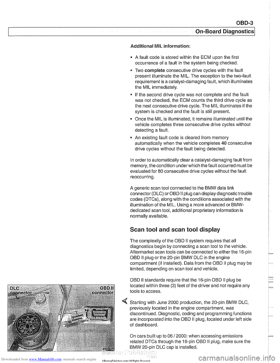
Starting with June 2000 production, the 20-pin BMW DLC,
previously located in the engine compartment, was
discontinued. Diagnostic, coding and programming functions
are incorporated into the OBD
II plug, located under left side
of dashboard.
On cars built up to 06
/ 2000: when accessing emissions
related DTCs through the 16-pin OBD
I1 plug, malte sure the
BMW 20-oin DLC
caD is installed.
Page 966 of 1002
Downloaded from www.Manualslib.com manuals search engine
OBD-6
On-Board Diagnostics
Fuel system monitoring. This monitor looks at the fuel
delivery needed (long
/short term fuel trim) for proper engine
operation based on programmed data. If too much or not
enough fuel is delivered over a predetermined time, a DTC is
set and the MIL illuminates.
Fuel trim refers to adiustments to base fuel schedule.
Lono- ., term fuel trim refers to gradual adjustments to the fuel
calibration adjustment as compared to short term fuel trim.
Long term fuel trim adjustments compensate for gradual
changes that occur over time.
Fuel system monitoring monitors the calculated injection time
(ti) in relation to enginespeed, load and precatalyticconverter
oxygen
sensor(s) signals.
Using this data, the system optimizes fuel delivery for all
engine operating conditions.
Evaporative system monitoring. This monitor checks the
the fuel storage system and related fuel lines for leaks. It can
detect very small leaks anywhere in the system.
A leak detection unit (LDP or DMTL) is used to pressurize the
evaporative control system on a continuous basis (as the
drive cycle allows) and to
check system integrity.
Drive cycle
The OED II drive cycle is an important concept in
understanding OBD
II requirements. The purpose of the drive
cycle is to run ail of the emission-related on-board diagnostics
over a broad range of driving conditions.
A drive cycle is considered complete when all of the
diagnostic monitors have run their tests without interruption.
~ora drive cycle to be initiated, the vehicle must be started
cold and brought up to
1 60°F and at least 40°F above its
original starting temperature.
Readiness codes
Inspection/maintenance (I/M) readiness codes are mandated
as part of OBD
II. The readiness code is stored aftercomplete
diagnostic monitoring of specified components and systems
is carried out. The readiness code function was designed to
prevent manipulating an
I/M emission test procedure by
clearing faults codes or disconnecting the ECM or battery.
Page 967 of 1002
Downloaded from www.Manualslib.com manuals search engine
On-Board Diagnostics
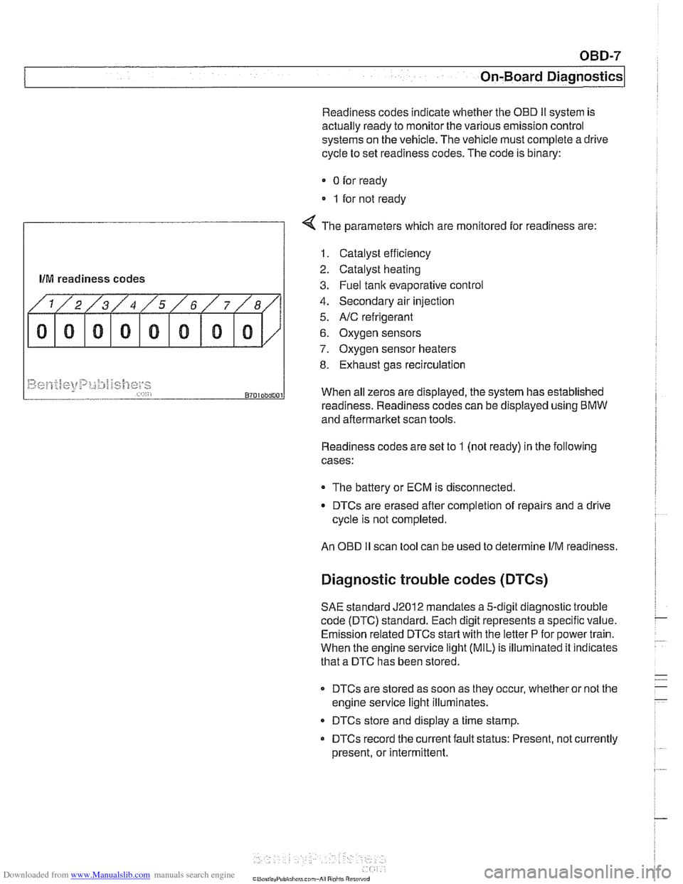
Readiness codes indicate whether the OED Ii system is
actually ready to monitor the various emission control
systems on the vehicle. The vehicle must complete a drive
cycle to set readiness codes. The code is binary:
0 for ready
1 for not ready
f
4 The parameters which are monitored for readiness are:
llM readiness codes
1. Catalyst efficiency
2. Catalyst heating
3. Fuel tank evaporative control
4. Secondary air injection
5.
NC refrigerant
6. Oxygen sensors
7. Oxygen sensor heaters
8. Exhaust gas recirculation
Readiness codes are set to 1 (not ready) in the following
cases:
~9~~.f~[<+t~t~p:,~;:#j~~{]~y~ ,,... , , 8701Dbd001
The battery or ECM is disconnected.
When
all zeros are displayed, the system has established
DTCs are erased after completion of repairs and a drive
cycle is not completed.
readiness. Readiness codes
can be displayed using BMW
and aftermarket scan tools.
An
OED II scan tool can be used to determine IIM readiness.
Diagnostic trouble codes (DTCs)
SAE standard J2012 mandates a 5-digit diagnostic trouble
code (DTC) standard. Each digit represents a specific value.
Emission related DTCs
start with the letter P for power train.
When the engine service
light (MIL) is illuminated it indicates
that a DTC has been stored.
DTCs are stored as soon as they occur, whether or not the
engine service light illuminates.
DTCs store and display a time stamp.
DTCs record the current fault status: Present, not currently
present, or intermittent.
Page 969 of 1002
Downloaded from www.Manualslib.com manuals search engine
On-Board Diagnostics
DIAGNOSTIC TROUBLE CODES
(DTCs)
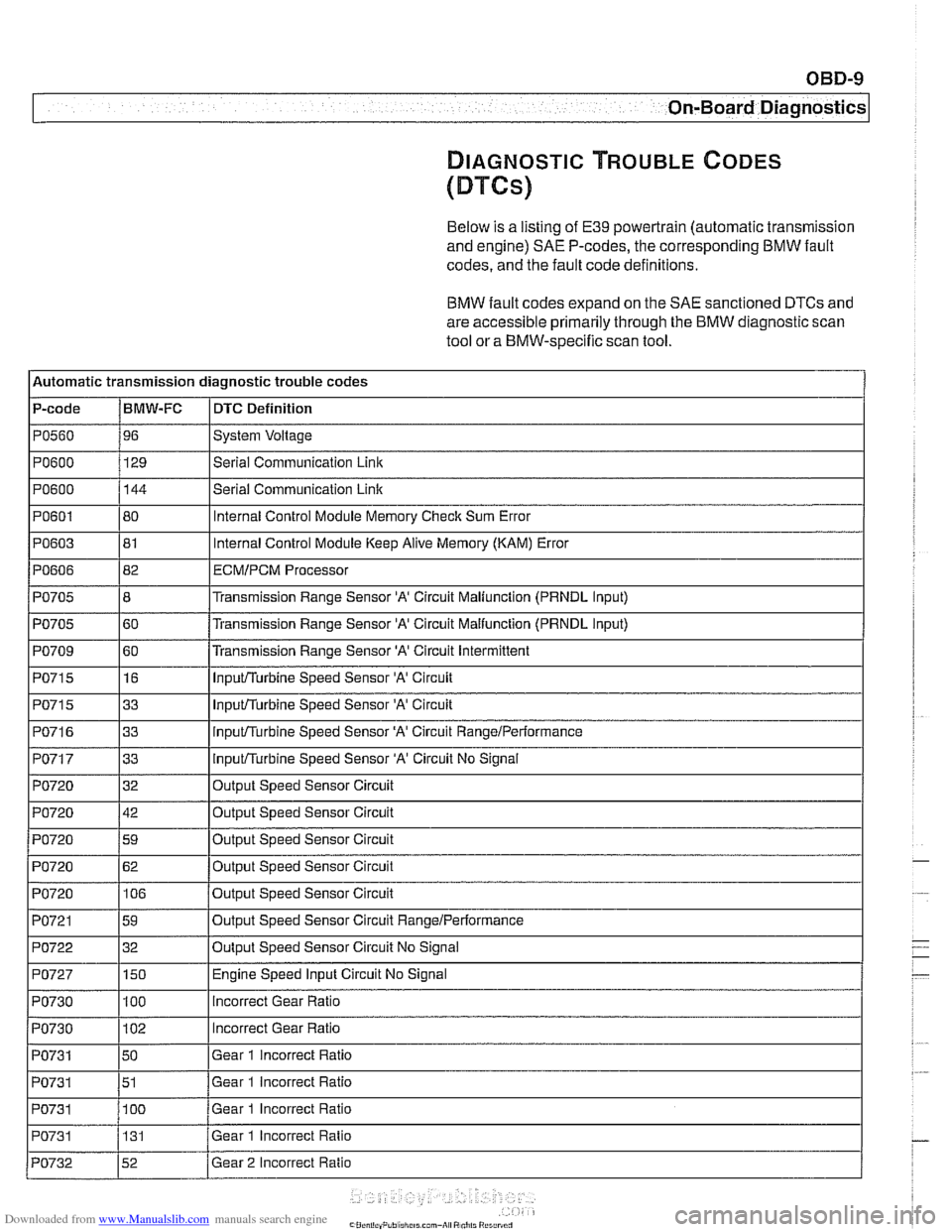
Below is a listing of E39 powertrain (automatic transmission
and engine)
SAE P-codes, the corresponding BMW fault
codes, and the fault code definitions.
BMW fault codes expand on the SAE sanctioned DTCs and
are accessible primarily through the BMW diagnostic scan
tool or a BMW-specific scan tool.
l~utomatic transmission diagnostic trouble codes
P-code
IBMW-FC I DTC Definition
Ip0560 196 ISystem Voltage I
IPO~OO I129 l~eriai Communication Link I
1~0715 116 I InpuVTurbine Speed Sensor 'A' Circuit I
PO600
PO601
PO603
PO606
PO705
PO705
PO709
144
80
81
82
8
60
60
PO71 5
PO71 6
PO717
PO720
PO720
PO720
I I
PO721 159 loutput Speed Sensor Circuit RangeIPerformance I
Serial Communication Link
Internal Control Module Memory Check Sum Error
Internal Control Module Keep Alive Memory (KAM) Error
ECMIPCM Processor
Transmission Range Sensor 'A' Circuit Maliunction (PRNDL Input)
Transmission Range Sensor
'A' Circuit Malfunction (PRNDL input)
Transmission Range Sensor
'A' Circuit Intermittent
I I'
1~0722 132 IOutput Speed Sensor Circuit No Signal I
33
33
33
32
42
59
PO720
I I
PO727 1150 I Engine Speed Input Circuit No Signal
InpuVTurbine Speed Sensor 'A' Circuit
inpuVTurbine Speed Sensor 'A' Circuit RangeiPerformance
InpuVTurbine Speed Sensor 'A' Circuit No Signal
Output Speed Sensor Circuit
Output Speed Sensor Circuit
Out~ut Speed Sensor Circuit
PO720 1106 /output Speed Sensor Circuit
62
Output Speed Sensor Circuit
PO730
PO730
PO731
PO731
PO731 I I
100
102
50
51
100
PO731
incorrect Gear Ratio
Incorrect Gear Ratio
Gear 1 incorrect Ratio
Gear 1 incorrect Ratio
Gear 1 Incorrect Ratio
PO732 152 /Gear 2 Incorrect Ratio
131
Gear
1 Incorrect Ratio
Page 970 of 1002
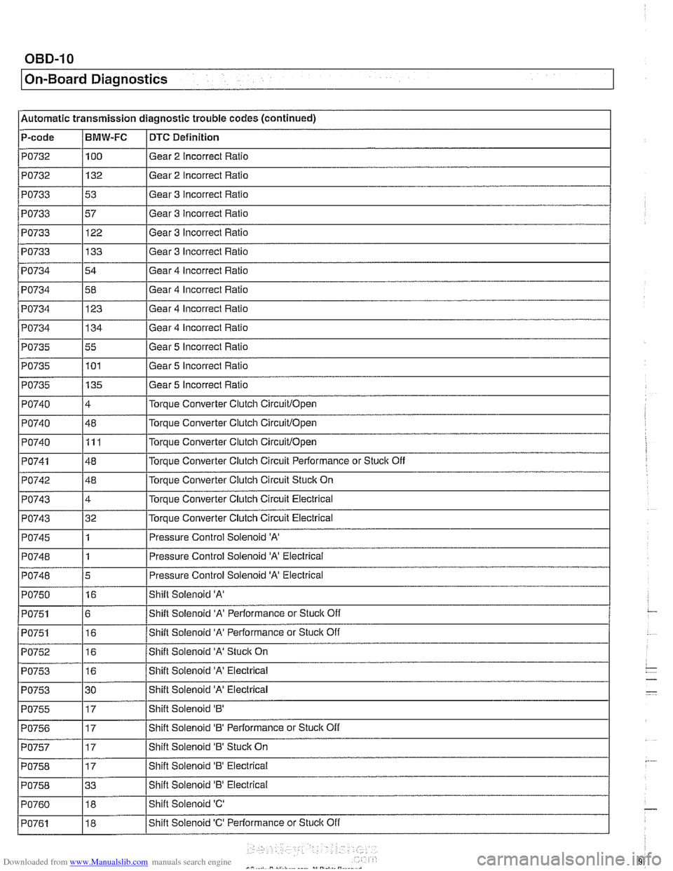
Downloaded from www.Manualslib.com manuals search engine
On-Board Diagnostics
l~utornatic transmission diagnostic trouble codes (continued) -
P-code /BMW-FC I DTC Definition - PO732
PO732
PO733
PO733
PO733
PO733
PO734 -
I I
I I
PO742 / 48 l~orque Converter Clutch Circuit Stuck On
PO734
100
132
53
57 122
133
54
PO735
PO735
PO735
PO740
PO740
PO740
PO741
I I
PO743 14 l~or~ue Converter Clutch Circuit Electrical
Gear
2 Incorrect Ratio
Gear 2 Incorrect Ratio
Gear 3 incorrect Ratio
Gear 3 Incorrect Ratio
Gear 3 Incorrect Ratio
Gear 3 Incorrect Ratio
Gear 4 Incorrect Ratio
Gear
4 Incorrect Rat10 PO734
I I
PO743 132 l~or~ue Converter Clutch Circuit Electrical
PO734 1134 IGear 4 Incorrect Ratio
123
55 101
135
4
48 111
48 Gear 5 Incorrect Ratio
Gear 5
Incorrect Ratio
Gear 5 Incorrect Ratio
Torque Converter Clutch
Circuitlopen
Torque Converter Clutch Circuitlopen
Torque Converter Clutch Circuitlopen
Torque Converter Clutch Circuit Performance or Stuclc Off
PO745
PO748
PO748
PO750
PO751
PO751
I I
PO755 117 IShift Solenoid '8' I
PO752
PO753
PO753
PO756 117 I~hift Solenoid '8' Performance or Stuck Off I
1
1
5
16
6 16 Pressure Control Solenoid 'A'
Pressure Control Solenoid 'A' Electrical
Pressure Control Solenoid
'A' Electrical
Shift Solenoid
'A'
Shift Solenoid 'A' Performance or Stuck Off
Shift Solenoid
'A' Performance or Stuck Off
16
16
30 Shift
Solenoid
'A' Stuck On
Shift Solenoid 'A' Electrical
Shift Solenoid
'A' Electrical
PO757
PO758
PO758
PO760
PO761
17
17
33 18
18 Shift
Solenoid '8' Stuclc On
Shift Solenoid
'8' Electrical
Shift Solenoid
'8' Electrical
Shift Solenoid
'C'
Shift Solenoid 'C' Performance or Stuclc Off
Page 971 of 1002
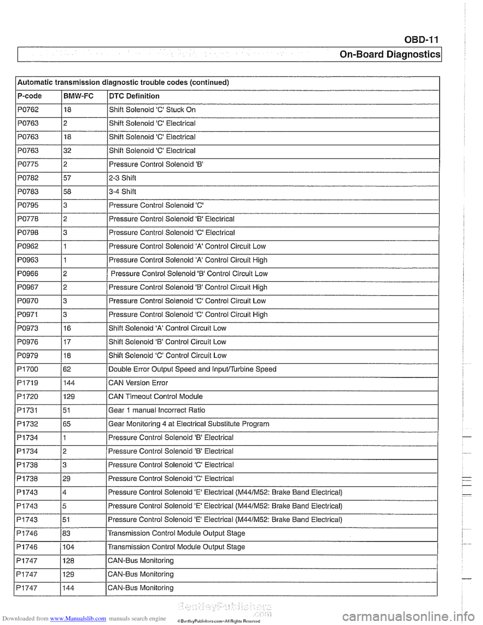
Downloaded from www.Manualslib.com manuals search engine
OBD-11
On-Board Diagnostics
Automatic transmission diagnostic trouble codes (continued)
P-code
PO762
PO763
PO763
PO763
PO775
PO782
PO783 I I
PO795
PO798
PO962
PO963
PO966
PO967
PO970
PO971
BMW-FC
18
2 18
32
2
57
58
I I -
DTC Definition
Shift Solenoid 'C' Stuck On
Shift Solenoid
'C' Electrical
Shift Solenoid
'C' Electrical
Shift Solenoid
'C' Electrical
Pressure Control Solenoid
'B'
2-3 Shift
3-4 Shift
PO778 12 I Pressure Control Solenoid 'B' Electrical
3
3
1
1
2
2
3
3
PO973
PO979
PI 700
PI719
PI720
Pi731
PI732
PI734
Pressure Control Solenoid 'C'
Pressure Control Solenoid
'C' Electrical
Pressure Control Solenoid
'A' Control Circuit Low
Pressure Control Solenoid 'A' Control Circuit High
Pressure Control Solenoid
'6' Control Circuit Low
Pressure Control Solenoid
'0' Control Circuit High
Pressure Control Solenoid 'C' Control Circuit Low
Pressure Control Solenoid 'C' Control Circuit
High
PI734
PI738
Pi738
PO976 117 IShift Solenoid 'B' Control Circuit Low
16
18
62 144
129
51
65
1
PI743
PI743
PI743
PI746
PI746 - Pi747
Shift Solenoid 'A' Control Circuit Low
Shift Solenoid 'C' Control Circuit Low
Double Error Output Speed and
inputflurbine Speed
CAN Version Error
CAN
Timeout Control Module
Gear
1 manual Incorrect Ratio
Gear Monitoring 4 at Electrical Substitute Program
Pressure
Control Solenoid 'B' Eieclrical
2
3
29
PI747
PI747
Pressure Control Solenoid 'B' Electrical
Pressure Control Solenoid
'C' Electrical
Pressure Control Solenoid
'C' Electrical
4
5
51
83 104 Pressure Control Solenoid
'E' Electrical (M44lM52: Brake
Band Electrical)
Pressure Control Solenoid
'E' Electrical (M44lM52: Bralte Band Electrical)
Pressure Control Solenoid
'E' Electrical (M44lM52: Brake Band Electrical)
Transmission Control Module Output Stage
Transmission Control Module Output Stage
129 128 CAN-Bus Monitoring CAN-Bus Monitoring
144 CAN-Bus Monitoring