Complete manual download BMW 528i 1998 E39 Owner's Manual
[x] Cancel search | Manufacturer: BMW, Model Year: 1998, Model line: 528i, Model: BMW 528i 1998 E39Pages: 1002
Page 277 of 1002
Downloaded from www.Manualslib.com manuals search engine
Camshaft Timing Chain
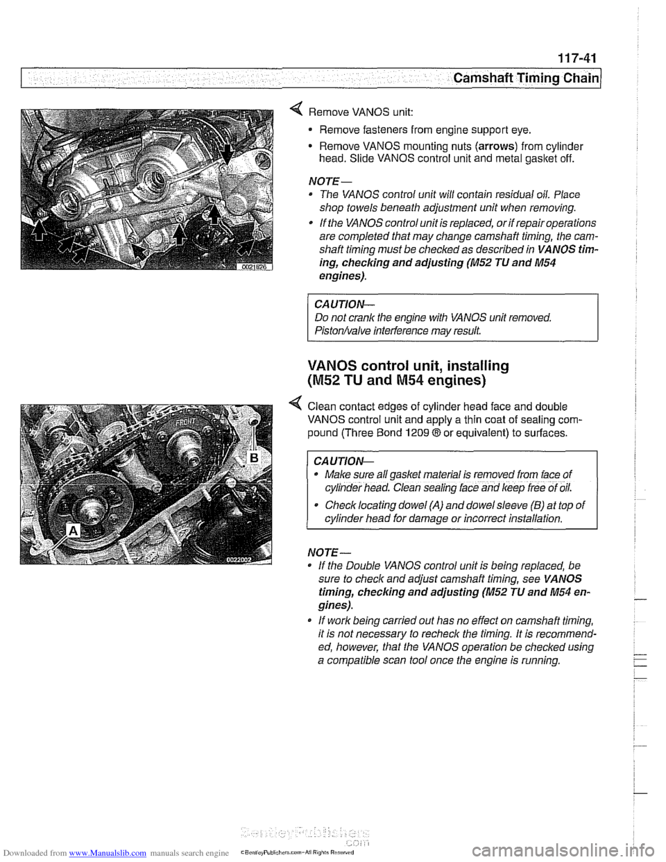
4 Remove VANOS unit:
Remove fasteners from engine support eye.
Remove VANOS mounting nuts (arrows) from cylinder
head. Slide VANOS control unit and metal gasltet off.
NOJE-
The VANOS control unit will contain residual oil. Place
shop towels beneath adjustment unit when removing.
If the VANOS control unit is replaced, or if repair operations
are completed that may change camshaft timing, the cam-
shaft timing must be checked as described in VANOS tim-
ing,
checlcing and adjusting (M52 JU and M54
engines).
CAUJION-
Do not crank the engine with VANOS unit removed.
Piston/valve interference may result.
VANOS control unit, installing
(M52 TU and M54 engines)
< Clean contact edges of cylinder head face and double
VANOS control unit and apply a thin coat of sealing com-
pound (Three Bond
1209 8 or equivalent) to surfaces.
I CAUJION-
. Make sure all gaskel material is removed from lace of
cyl~nder head. Clean sealing lace and keep lree of oil.
Checklocating dowel (A) and dowelsleeve (B) at top of
cylinder head for damage or incorrect installation.
NO
JE -
If the Double VANOS control unit is beino reolaced. be -.
sure to check and adjust camshaft timing, see VA NOS
timing, checking and adjusting (M52 JU and M54 en-
gines).
* If work being carried out has no effect on camshaft timing,
it is not necessary to recheck the timing. It is recommend-
ed, however, that the VANOS operation be checked using
a compatible scan tool once the engine is running.
Page 281 of 1002
Downloaded from www.Manualslib.com manuals search engine
Camshaft Timing chain1
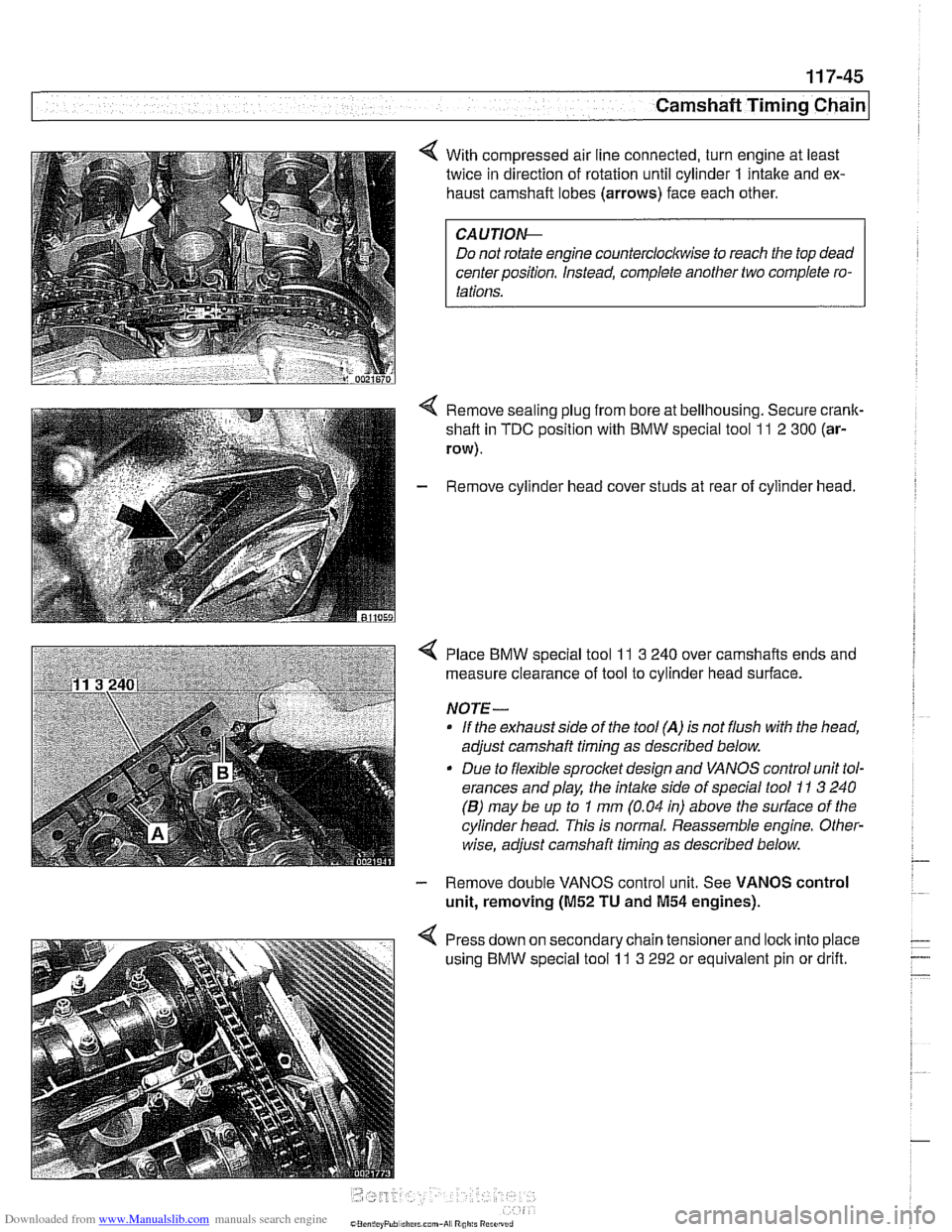
< With compressed air line connected, turn engine at least
twice in direction of rotation until cylinder
1 intake and ex-
haust camshaft lobes (arrows) face each other.
Do not rotate engine counterclockwise to reach the top dead
center position. Instead, complete another two complete ro-
Remove sealing plug from bore at bellhousing. Secure crank-
shaft in
TDC position with BMW special tool 11 2 300 (ar-
row).
- Remove cylinder head cover studs at rear of cylinder head.
< Place BMW special tool 11 3 240 over camshafts ends and
measure clearance of tool to cylinder head surface.
NOTE-
If the exhaust side of the tool (A) is not flush with the head,
adjust camshaft timing as described below.
Due to flexible sprocket design and VANOS control unit tol-
erances and play, the
intake side of special tool 11 3 240
(B) may be up to 1 mm (0.04 in) above the surface of the
cylinder head. This is normal. Reassemble engine. Other-
wise, adjust camshaft timing as described below.
- Remove double VANOS control unit. See VANOS control
unit, removing
(M52 TU and M54 engines).
< Press down on secondary chain tensionerand lock into place
using BMW special tool
11 3 292 or equivalent pin or drift.
Page 317 of 1002
Downloaded from www.Manualslib.com manuals search engine
Camshaft Timing chain1 - -- -
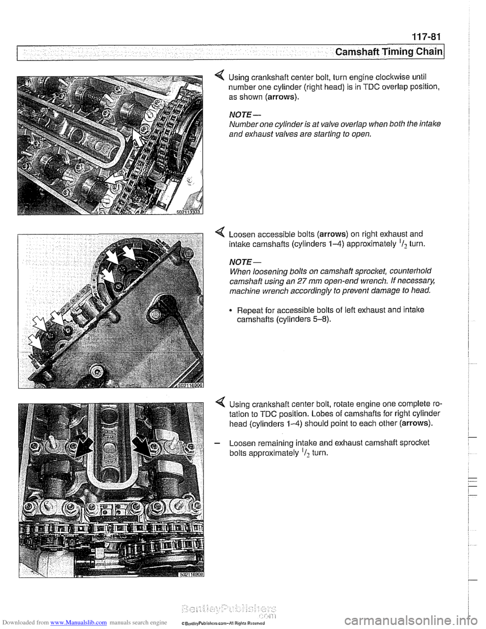
Using crankshaft center bolt, turn engine clockwise until
number one cylinder (right head) is in
TDC overlap position,
as shown
(arrows).
NOTE-
Number one cylinder is at valve overlap when both the intale
and exhaust valves are starting to open.
< Loosen accessible bolts (arrows) on right exhaust and
intake camshafts (cylinders
1-4) approximately 'I2 turn.
NOTE-
When loosening bolts on camshaft sprocket, counterhold
camshaft using an
27 mm open-end wrench. If necessary.
machine wrench accordingly to prevent damage
to head.
Repeat for accessible bolts of left exhaust and intake
camshafts (cylinders
5-8).
Using crankshaft center bolt, rotate engine one complete ro-
tation to
TDC position. Lobes of camshafts for right cylinder
head (cylinders
1-4) should point to each other (arrows).
- Loosen remaining intake and exhaust camshaft sprocltet
bolts approximately
'I2 turn.
Page 341 of 1002
Downloaded from www.Manualslib.com manuals search engine
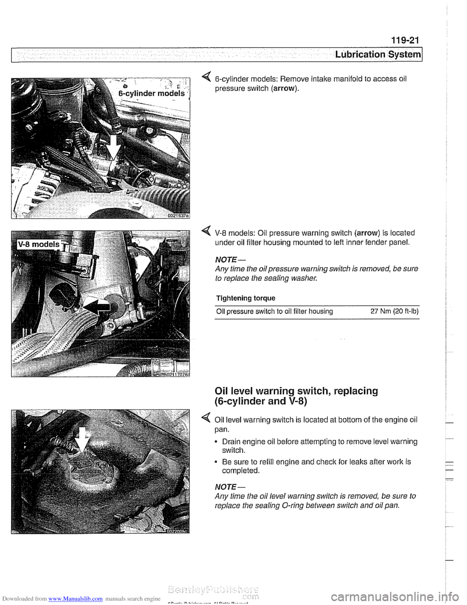
< 6-cylinder models: Remove intake manifold to access oil
pressure switch
(arrow).
V-8 models: Oil pressure warning switch (arrow) is located
under oil filter housing mounted to left inner fender panel.
NOTE-
Any time the oilpressure warning switch is removed, be sure
to replace the sealing washer.
Tightening torque Oil
~ressure switch to oil filter housins 27 Nrn (20 ft-lb)
Oil level warning switch, replacing
(6-cylinder and
V-8)
4 Oil level warning switch is located at bottom of the engine oil
pan.
Drain engine oil before attempting to remove level warning
switch.
Be sure to refill engine and check for leaks after work is
completed.
NOTE-
Any time the oil level warning switch is removed, be sure to
replace the sealing O-ring between switch and oil pan.
Page 356 of 1002
Downloaded from www.Manualslib.com manuals search engine
I lgnition System
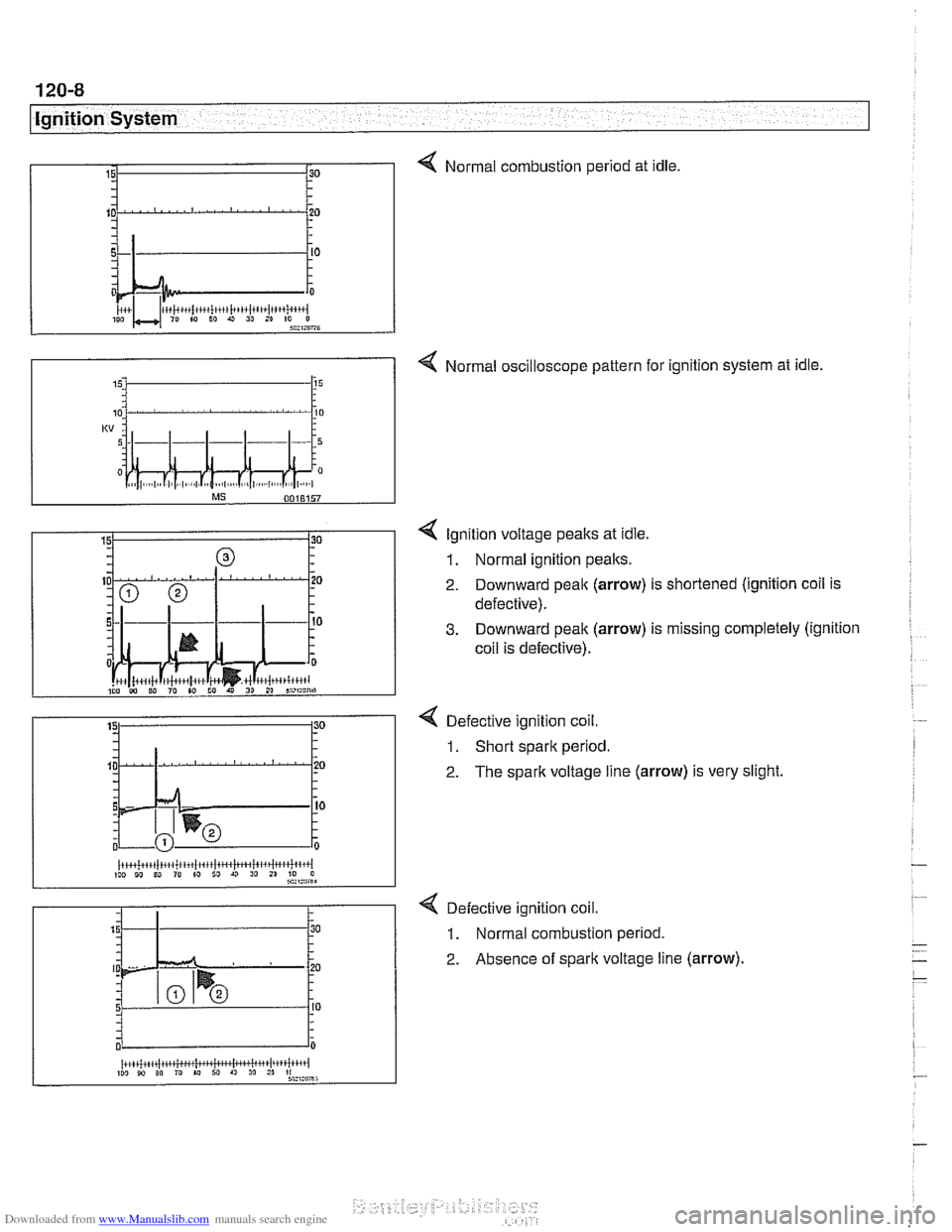
4 Normal combustion period at idle.
4 Normal oscilloscope pattern for ignition system at idle.
15. 15
4 lgnition voltage peaks at idle.
1. Normal ignition peaks.
2. Downward peak (arrow) is shortened (ignition coil is
defective).
3. Downward peak (arrow) is missing completely (ignition
coil is defective).
4 Defective ignition coil.
1. Short spark period.
2. The spark voltage line (arrow) is very slight
< Defective ignition coil.
1. Normal combustion period.
2. Absence of spark voltage line (arrow).
(r+~+~+~(.~i+~/.~~itlt~~(tit~lii~~jt~~~i~ittiii~l IW 10 ED 10 (0 ID U 10 11 70 0 sa,ma,
2 . 15 - .
5 - - - 0
30
.
.
20 .
I0 - -
0
iiiCi;kiW*huiMwiritil~tiii 110 10 00 ro w M A, 30 2" *:,:mu
Page 362 of 1002
Downloaded from www.Manualslib.com manuals search engine
I Ignition System
Camshaft position sensors
The camshaft position sensors are used by the englne man-
agement system for VANOS control, sequential fuel injection
and knock control.
Intake camshaft position sensor, replacing
(M52,M52 TU
and M54 engines)
- Make certain ignition has been turned off.
- Remove plastic cover from above fuel injectors by prying off
bolt covers and removing cover mounting bolts.
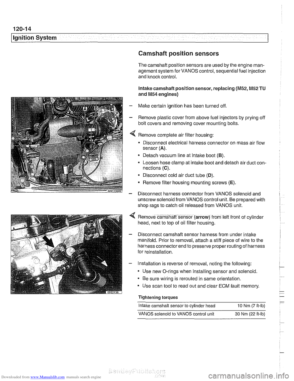
Remove complete air filter housing:
Disconnect electrical harness connector on mass air flow
sensor
(A).
Detach vacuum line at intake boot (B).
Loosen hose clamp at intake boot and detach air duct con-
nections
(C).
* Disconnect cold air duct tube (D).
Remove filter housing mounting screws (E).
- Disconnect harness connector from VANOS solenoid and
unscrew solenoid from VANOS control unit. Be prepared with
shop rags to catch oil released from VANOS unit.
Remove camshaft sensor (arrow) from
left front of cyl~nder
head, next to top of oil filter housing.
Disconnect camshaft sensor harness from under intake
manifold. Prior to removal, attach a stiff piece of wire to the
harness connector end to preserve proper routing of harness
for reinstallation.
Installation is reverse of removal, noting the following:
Use new O-rings when installing sensor and solenoid.
Be sure wiring is rerouted in same orientation.
Use scan tool to read out and clear
ECM fault memory
Tightening torques
-
Intake camshaft sensor to cylinder head 10 Nrn (7 ft-lb)
VANOS solenoid to VANOS control unit 30 Nm (22 ft-lb)
Page 370 of 1002
Downloaded from www.Manualslib.com manuals search engine
.-. .
Battery, Starter, Alternator
Warnings and cautions
WARNING -
Wear goggles, rubber gloves, and a rubber apron when
working around the battery or battery acid (electrolyte).
Battery acid contains sulfuric acid and can cause skin
irritation and burning.
If acid is spilled on your skin or
clothing, flush the area at once with large quantities of
water. If electrolyte gets into your eyes, flush them with
large quantities of clean water for several minutes and
call a physician.
Batteries that are being charged or are fully charged
give off explosive hydrogen gas. Keep sparks and open
flames away. Do not
smoke.
CA UTIOI\C
Only use a digital multimeter when testing automotive elec-
trical components.
. If a repair procedure specifies disconnecting the bat-
tery, follow the instruction for safety reasons.
Prior to disconnecting the battery, read the battery dis-
connection cautions in
001 General Cautions and
Warnings.
Models with MS43 engine management: Allow at least
3 minutes to elapse after turning ignition ley to OFFpo-
sition before disconnecting battery. This willallow sum-
cient tinie to complete the DMJL (fuel tank pressure)
test
* Disconnecting the battery cables may erase fault codes
stored in ECM memory.
Always disconnect the negative
(-) battery cable first
and reconnect it last. Cover the battery post with an in-
sulating material whenever the cable is removed.
Do not disconnect battery, alternator or starter wires
while the engine is running.
0 Never reverse the battery cables. Even a momentary
wrong connection can damage the alternator or other
electrical components.
Do not depend on the color of insulation to tell battery
positive and negative cables apart. Label cables before
removing.
The slide-tilt sunroof may fail to function properly
after
disconnecting and reconnecting the battery. Reinitial-
ize sunroof as described in 540 Sunroof.
Page 373 of 1002
Downloaded from www.Manualslib.com manuals search engine
Battery, Starter, ~lternatorl
WARNING-
Always wear protective goggles and clothing when perform-
ing a load test.
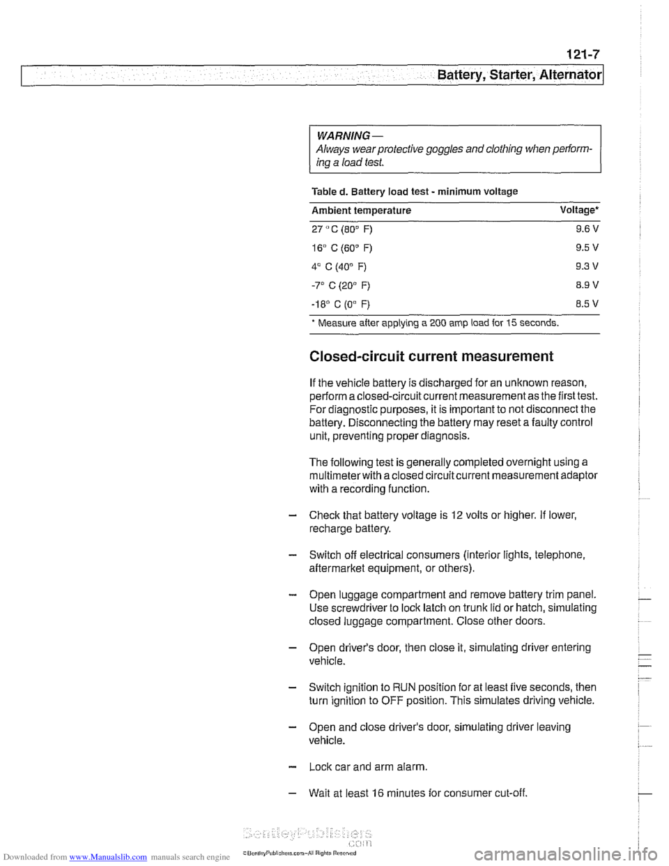
Table
d. Battery load test - minimum voltage
Ambient temperature Voltage*
27
" C (80" F) 9.6 V
-I 8' C (0"
F) 8.5 V
* Measure
after applying a 200 amp load for 15 seconds.
Closed-circuit current measurement
If the vehicle battery is discharged for an unknown reason,
perform a closed-circuit current measurement as the first test.
For diagnostic purposes, it is important to not disconnect the
battery. Disconnecting the battery may reset a faulty control
unit, preventing proper diagnosis.
The following test is generally completed overnight using a
multimeterwith a closed circuitcurrent measurement adaptor
with a recording function
- Check that battery voltage is 12 volts or higher. If lower,
recharge battery.
- Switch off electrical consumers (interior lights, telephone,
aftermarket equipment, or others).
- Open luggage compartment and remove battery trim panel.
Use screwdriver to lock latch on trunk lid or hatch, simulating
closed luggage compartment. Close other doors.
- Open driver's door, then close it, simulating driver entering
vehicle.
- Switch ignition to RUN position for at least five seconds, then
turn ignition to OFF position. This simulates driving vehicle.
- Open and close driver's door, simulating driver leaving
vehicle.
- Lock car and arm alarm.
- Wait at least 16 minutes for consumer cut-off.
Page 379 of 1002
Downloaded from www.Manualslib.com manuals search engine
Battery, Starter, ~lternatorl
Charging system quick-check
Use a digital multimeter to measure voltage across the bat-
tery terminals with key off and then again with engine running.
Battery voltage should be about 12.6 volts with key off and be-
tween 13.5 and 14.5 volts with engine running.
NOTE-
The regulated voltage (engine running) should be between
13.2 and 14.5, depending on temperature andoperating con-
ditions.
If the voltage is higher than 14.8, the voltage regula-
tor or
mulitfunction controller is most likely faulty
Check for clean and tight battery cables. Check ground cable
running from negative
(-) battery terminal to chassis and
ground cable running from engine to chassis. Check alterna-
tor drive belt condition and tension.
Charging system, checking
CAUTIOI\C
* Do not disconnect the battery while the engine is running.
Damage to the alternator and/or engine electronic systems
may result.
Only use a digital multimeter when testing charging
system components.
--7
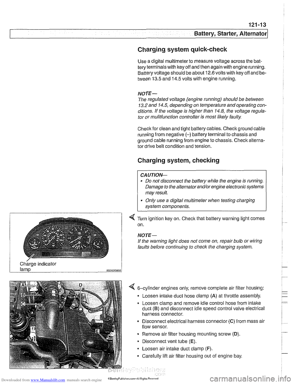
4 Turn ignition key on. Check that battery warning light comes
on.
NOTE-
If the warning light does not come on, repair bulb or wiring
faults before continuing to checlc the charging system.
/ Charge indicator
502820805
4 6-cylinder engines only, remove complete air filter housing:
Loosen
intake duct hose clamp (A) at throttle assembly.
Loosen clamp and remove idle control hose from intake
duct
(B) and disconnect idle speed control valve electrical
harness connector.
Disconnect electrical harness connector
(C) from mass air
flow sensor.
Remove air filter housing mounting screw
(D).
Disconnect vent tube (E).
Loosen air intake duct clamp (F).
Carefully lift air filter housing out of engine bay.
Page 381 of 1002
Downloaded from www.Manualslib.com manuals search engine
Battery, Starter, ~lternatorl
Alternator, removing and installing
(6-cylinder engine)
A replacement alternator should have the same rating as the
original. Alternator manufacturer and ampere rating are nor-
mally marked on the alternator housing.
- Disconnect negative (-) battery cable.
CAUTION-
Prior to disconnecting the batteg read the battery discon-
nection cautions given
in 001 General Warnings and Cau-
I tions.
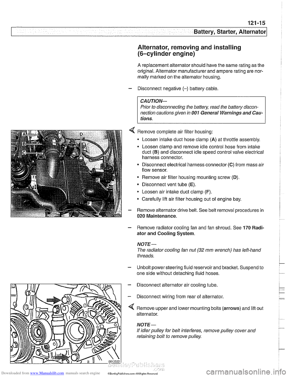
Remove complete air filter housing:
Loosen intake duct hose clamp
(A) at throttle assembly.
Loosen clamp and remove idle control hose from intake
duct
(B) and disconnect idle speed control valve electrical
harness connector.
Disconnect electrical harness connector
(C) from mass air
flow sensor.
* Remove air filter housing mounting screw (D),
Disconnect vent tube (E).
Loosen air intake duct clamp (F).
Carefully lifl air filter housing out of engine bay.
Remove alternator drive belt. See belt removal procedures in
020 Maintenance.
- Remove radiator cooling fan and fan shroud. See 170 Radi-
ator and Cooling System.
NOTE-
The radiator cooling fan nut (32 mm wrench) has left-hand
threads.
- Unbolt power steering fluid reservoir and bracket. Suspend to
one side without detaching fluid hoses.
- Disconnect alternator air cooling tube.
- Disconnect wiring from rear of alternator.
'4 Remove upper and lower mounting bolts (arrows) and lift
alternator.
If idler pulley for belt interferes, remove pulley cover and
retaining bolt to remove pulley. out