Complete manual download BMW 528i 1998 E39 Repair Manual
[x] Cancel search | Manufacturer: BMW, Model Year: 1998, Model line: 528i, Model: BMW 528i 1998 E39Pages: 1002
Page 787 of 1002
Downloaded from www.Manualslib.com manuals search engine
340-25
Brakes
- Remove complete exhaust system as described in 180 Ex-
haust System.
- Remove center tunnel heat shield.
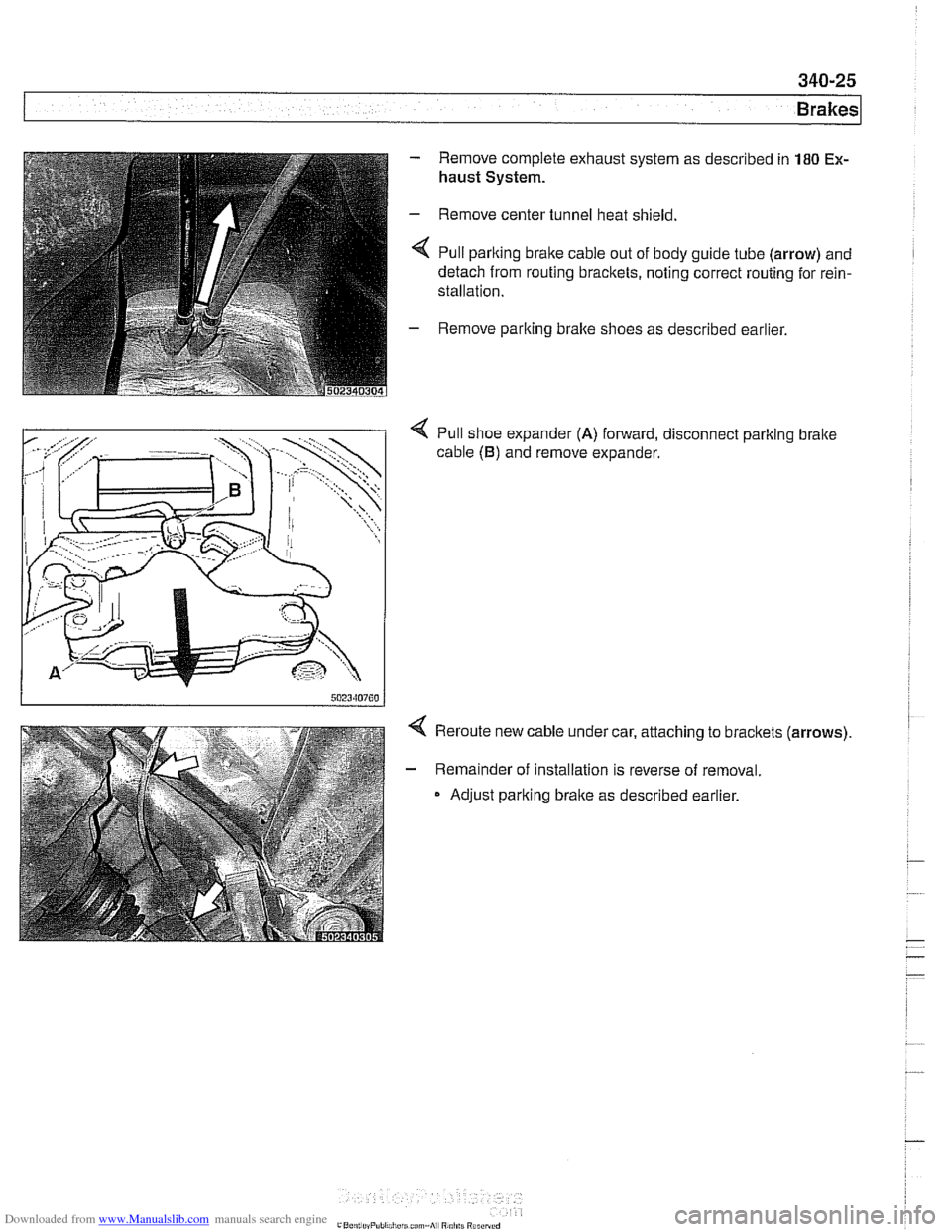
< Pull parlting brake cable out of body guide tube (arrow) and
detach from routing bracltets, noting correct routing for rein-
stallation.
- Remove parlting bralte shoes as described earlier.
4 Pull shoe expander (A) forward, disconnect parlting bralte
cable
(B) and remove expander.
4 Reroute new cable under car, attaching to bracltets (arrows).
- Remainder of installation is reverse of removal.
Adjust parking brake as described earlier.
Page 808 of 1002
Downloaded from www.Manualslib.com manuals search engine
[Fenders, Engine Hood
This repair group covers replacement of the front fenders and
removal and installation of the engine hood.
NOJE-
The body is painted at the factory affer assembly Realign-
ment of body panels may expose unpainted metal. Paint all
exposed metal once the work is complete.
Special tools
Most body repairs can be performed using regular automotive
service tools. Some BMW special tools are required to set
body pieces into the
service positions.
Front fender, removing and installing
- Raise front of vehicle and remove wheel
WARNING-
Make sure that the car is firmly supported on jack stands de-
signed for the purpose.
Placejaclr stands beneath structural
chassis points. Do not place jack stands under suspension
parts.
- Raise hood to service position. See Hood, raising to ser-
vice position.
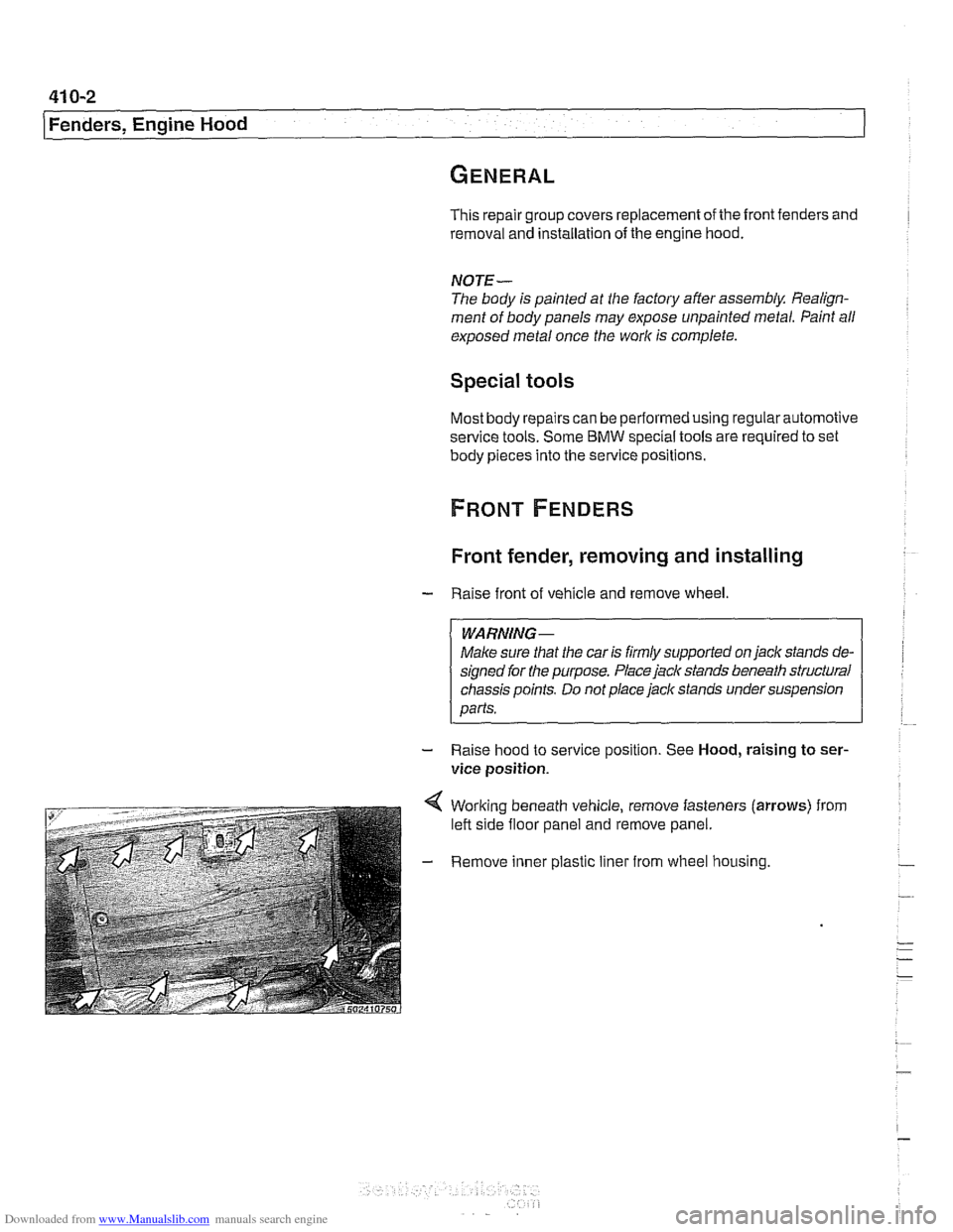
4 Working beneath vehicle, remove fasteners (arrows) from
left side floor panel and remove panel.
- Remove inner plastic liner from wheel housing.
Page 814 of 1002
Downloaded from www.Manualslib.com manuals search engine
41 0-8
(Fenders, Engine Hood
Hood, aligning
When installing the hood, align the hinges as close to the orig-
inal painted surface as possible. Movement of the hood on its
attaching hardware may require touch-up paint.
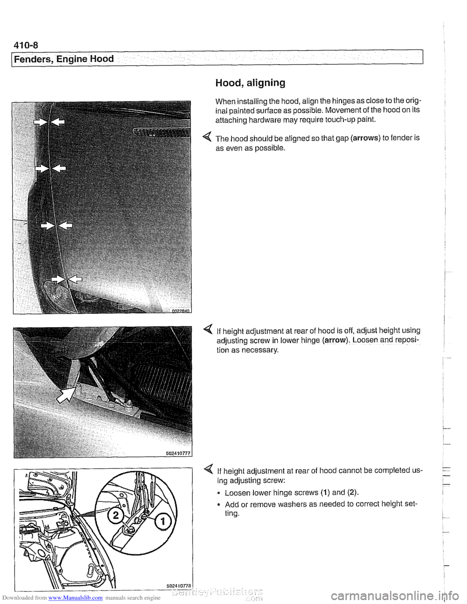
The hood should be aligned so that gap
(arrows) to fender is
as even as possible.
4 If height adjustment at rear of hood is off, adjust height using
adjusting screw in lower hinge
(arrow). Loosen and reposi-
tion as necessary.
If height adjustment at
ing adjusting screw: rear
of
hood cannot be completed us-
Q Loosen lower hinge screws (1) and (2).
Add or remove washers as needed to correct height set-
ting.
Page 822 of 1002
Downloaded from www.Manualslib.com manuals search engine
Doors
~obr adjustment
Front fender to
4.25 mm i 0.25 mm (0.17 i- 0.01 in)
front door gap
Front
door to 4.5 mm i 0.25 mm (0.18 i 0.01 in)
rear door gap
Rear door to rear fender 4.0 mm i 0.25 mm (0.16 i 0.01 in)
Permissible deviation 1 .O mm (0.04 in)
from
~arallel
Tightening torque
Door hinge to door frame
20 Nm (15 it-lb)
Door check, replacing
WARNING -
E39 cars are fitted with side-impact airbags in the front doors
and optional side impact
airbags in the rear doors. When
servicing doors, always disconnect the negative
(-) battery
terminal. See
721 Airbag System (SRS) for cautions and
procedures relating to the
airbag system.
- Close door window completely.
- Disconnect negative (-) battery cable.
CAUTION-
Prior to disconnecting the batter)! read the battery discon-
nection cautions given in
001 General Cautions and
Warnings.
- Remove interior door panel. See Door trim panels, remov-
ing and installing.
- Where applicable, remove side-impact airbag from door. See
721 Airbag System (SRS). Remove door vapor barrier.
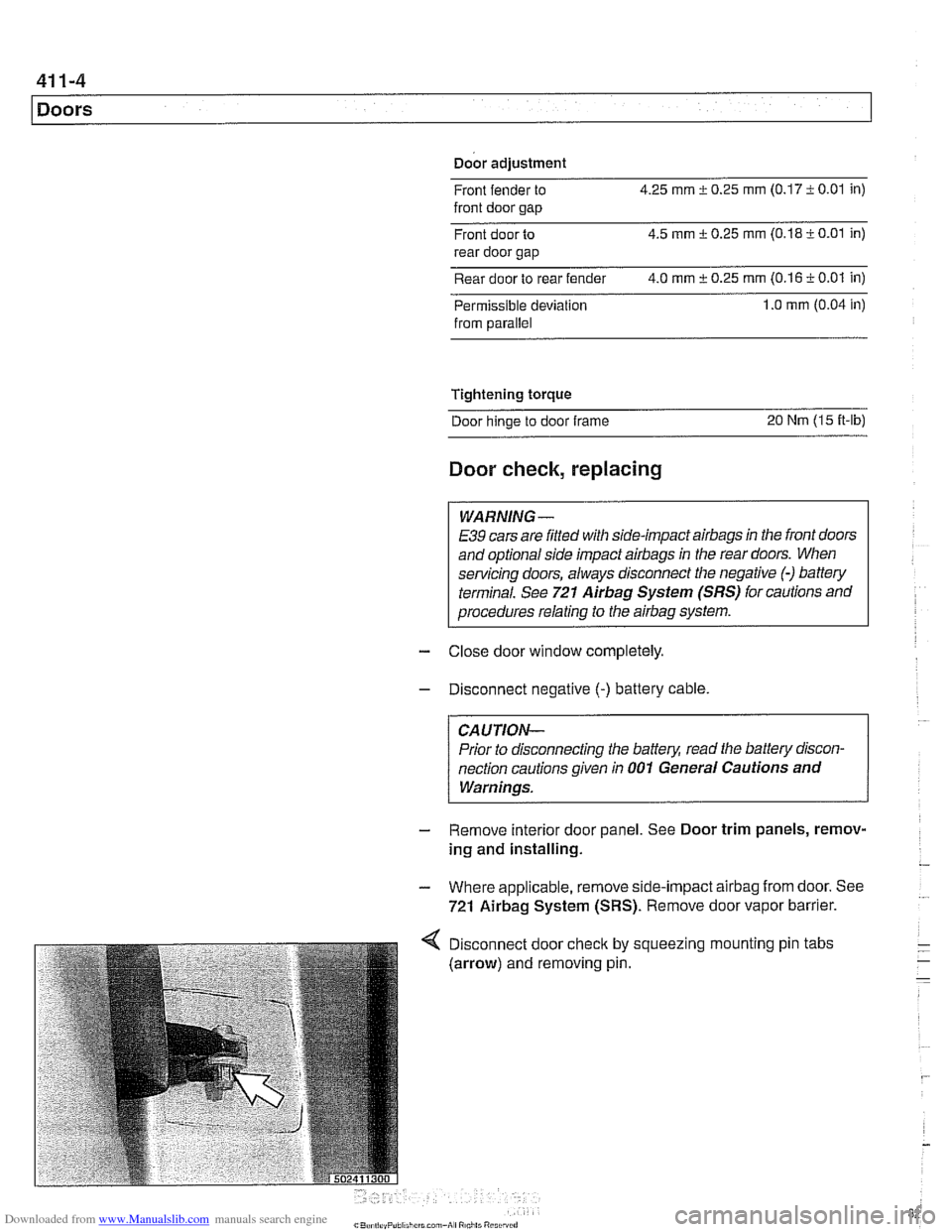
Disconnect door
check by
(arrow) and removing pin. squeezing I mounting
pin tabs
Page 830 of 1002
Downloaded from www.Manualslib.com manuals search engine
41 2-2
Trunk Lid, Tailgate
This repair group covers trunk lid and tailgate removal and in-
stallation. Also included here are replacement proceduresfor
the gas-charged support struts that hold the trunk lid or tail-
gate in the open position.
NO JE -
The body is painted at the factory after assembly. Realign-
ment of body panels may expose unpainted metal. Paint all
exposed metal once the
work is complete.
Trunk lid, removing and installing
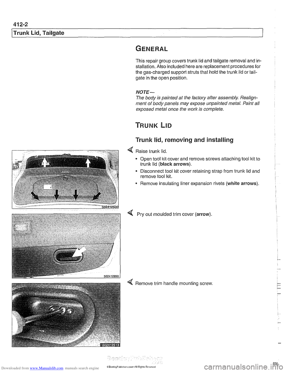
4 Raise trunlc lid.
Open tool ltit cover and remove screws attaching tool kit to
trunlc lid (black arrows).
Disconnect tool ltit cover retaining strap from
trunk lid and
remove tool kit.
Remove insulating liner expansion rivets (white arrows).
4 Pry out moulded trim cover (arrow).
Page 931 of 1002
Downloaded from www.Manualslib.com manuals search engine
Sunroof, normalization
During normalization the mechanical end positions of sunroof
movement are detected and stored by the General Module
(GM
Ill).
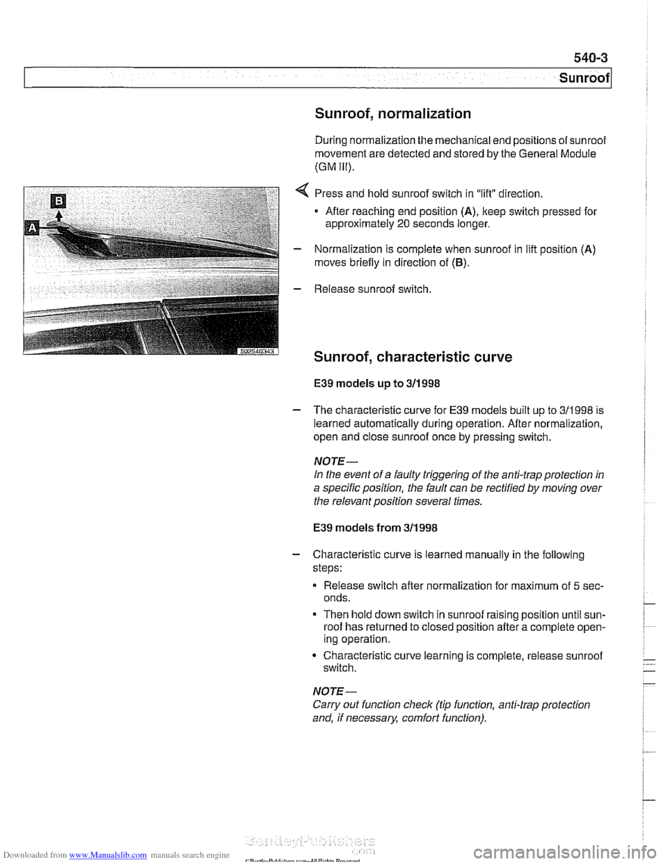
,:..I:,* *:3F$&-T , a,.,-. . 2 *i;.'I . :i_(,*,,_ _* Press and hold sunroof switch in "lift" direction.
Afler reaching end position
(A), keep switch pressed for
approximately
20 seconds longer.
- Normalization is complete when sunroof in lifl position (A)
moves briefly in direction of (6).
E39 models up to 311 998
- The characteristic curve for E39 models built up to 311998 is
learned automatically during operation. After normalization,
open and close sunroof once by pressing switch.
NOTE-
In the event of a faulty triggering of the anti-trap protection in
a specific position, the fault can be rectified
by moving over
the relevant position several times.
E39 models from 311 998
- Characteristic curve is learned manually in the following
steps:
Release switch after normalization for maximum of
5 sec-
onds.
Then hold down switch in sunroof raising position until sun-
roof has returned to closed position after a complete open-
ing operation.
Characteristic curve learning is complete, release sunroof
switch.
NOTE-
Carry out function check (tip function, anti-trap protection
and, if necessary, comfort function).
Page 940 of 1002
Downloaded from www.Manualslib.com manuals search engine
I Seat Belts
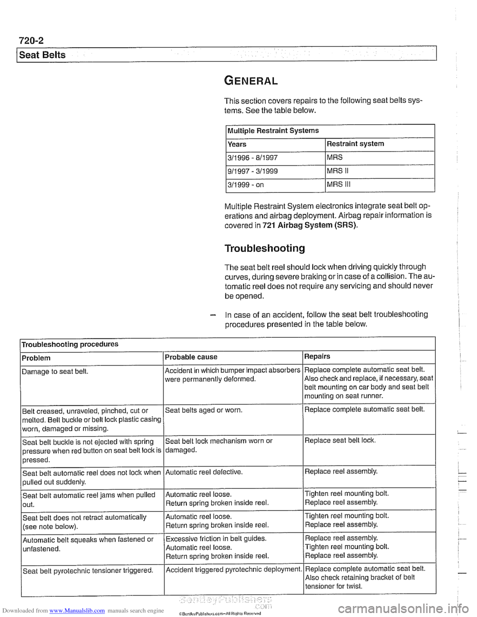
This section covers repairs to the following seat belts sys-
tems. See the table below.
IMultIple Restraint Systems I
Years
311 996 - 811 997
Multiple Restraint System electronics integrate seat belt op-
erations and
airbag deployment. Airbag repair information is
covered
in 721 Airbag System (SRS).
Troubleshooting
The seat belt reel should lock when driving quicltly through
curves,
during severe braking or in case of a collision. The au-
tomatic reel does not require any servicing and should never
be opened.
- In case of an accident, follow the seat belt troubleshooting
procedures presented
in the table below.
Troubleshooting procedures
Belt creased, unraveled, pinched, cut or
melted. Belt buckle or belt loclt plastic casing Repairs
Replace complete automatic
seat belt.
Also
checlt and replace, if necessary, seat
Problem
Damage to seat
belt.
worn, damaged or missing.
Seat belt bucltle is not ejected with spring
pressure when red button on seat belt loclt is
>--- I I
Automatic belt soueaks when fastened or I~xcessive friction in belt guides. I Replace reel assembly.
Probable
cause
Accident in which bumper impact absorbers
were permanently deformed.
Seat belts aged or worn.
pressed.
Seat belt automatic reel does not lock when
pulled out suddenly.
Seat belt automatic reel jams when pulled
out.
Seat belt does not retract automatically
(see note below).
Automatic reel loose. Return sorino broken inside reel. belt mounting on car body and
seat belt
mounting on seat runner.
Replace complete automatic seat belt.
Seat belt
loclt mechanism worn or
damaged.
Tighten reel mounting bolt Replace reel assembly.
Replace seat belt lock.
Automatic reel defective.
Automatic reel loose. Return spring
broken inside reel.
Automatic reel loose.
Return spring brolten inside reel. Replace reel
assembly.
Tighten reel mounting
bolt.
Replace reel assembly.
Tighten reel mounting bolt. Replace reel assembly.
~ ~-~~ , - I'
Replace complete automatic seat belt.
Also check retaining bracket of belt
Seat belt
pyrotechnic tensioner triggered. Accident triggered pyrotechnic deployment.
Page 956 of 1002
Downloaded from www.Manualslib.com manuals search engine
721 -8
(Airbag System (SRS)
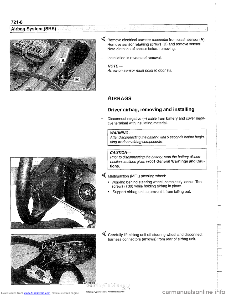
4 Remove electrical harness connector from crash sensor (A).
Remove sensor retaining screws (6) and remove sensor.
Note direction of sensor before removing.
- Installation is reverse of removal,
NOTE -
Arrow on sensor must point to door sill.
Driver airbag, removing and installing
- Disconnect negative (-) cable from battery and cover nega-
tive terminal with insulating material.
WARNING-
After disconnecting the batter)! wait 5 seconds before begin-
ning work on
airbag components.
CAUTION-
Prior to disconnecting the batter)! read the battery discon-
nection cautionsgiven
in001 General Warnings and Cau-
tions.
4 Multifunction (MFL) steering wheel:
. Working behind steering wheel, completely loosen Torx
screws
(T30) while holding airbag in place.
Support
airbag unit to prevent it from falling out.
Page 957 of 1002
Downloaded from www.Manualslib.com manuals search engine
721 -9
Airbaq System ~SRS)~
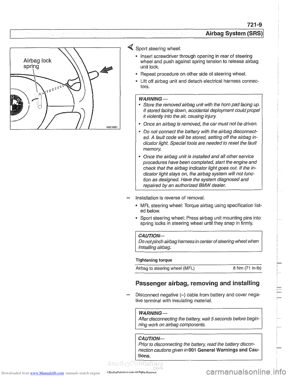
4 Sport steering wheel:
Insert screwdriver through opening in rear of steering
wheel and push against spring tension to release
airbag
unit lock.
Repeat procedure on other side of steering wheel.
Lift off
airbag unit and detach electrical harness connec-
tors.
WARNING-
Store the removedairbag unit with the horn pad facing up.
If stored facing down, accidental deployment could propel
it violently into the air, causing injury.
Once an
airbag is removed, the car must not be driven.
Do not connect the battery with the
airbag disconnect-
ed. A fault code will be stored, setting off the
airbag in-
dicator light Special tools are needed to reset the fault
memory
Once the
airbag unit is installed and all other service
procedures have been completed, start the engine and
check that the
airbag indicator light goes out. If the in-
dicator light stays on, the
airbag system will not func-
tion as designed. Have the system diagnosed and
repaired by an authorized
BMW dealer.
- Installation is reverse of removal.
MFL steering wheel: Torque airbag using specification list-
ed below.
- Sport steering wheel: Press airbag unit mounting pins into
spring
loclts in steering wheel until they snap in firmly.
CAUTION--
Do notpinch airbag harness in center of steering wheel when
installino
airbaa.
Tightening torque
Airbao to steerino wheel IMFL) 8 Nm (71 in-lb)
Passenger airbag, removing and installing
- Disconnect negative (-) cable from battery and cover nega-
tive terminal with insulating material.
--
WARNING -
After disconnecting the batteg wait 5 seconds before begin-
nina work on airbaa components.
Prior to disconnecting the battery, read the battery discon-
nection cautionsgiven in001 General Warnings and
Cau-
Page 960 of 1002
Downloaded from www.Manualslib.com manuals search engine
721-12
Airbag System (SRS)
Head protection airbag (HPS)
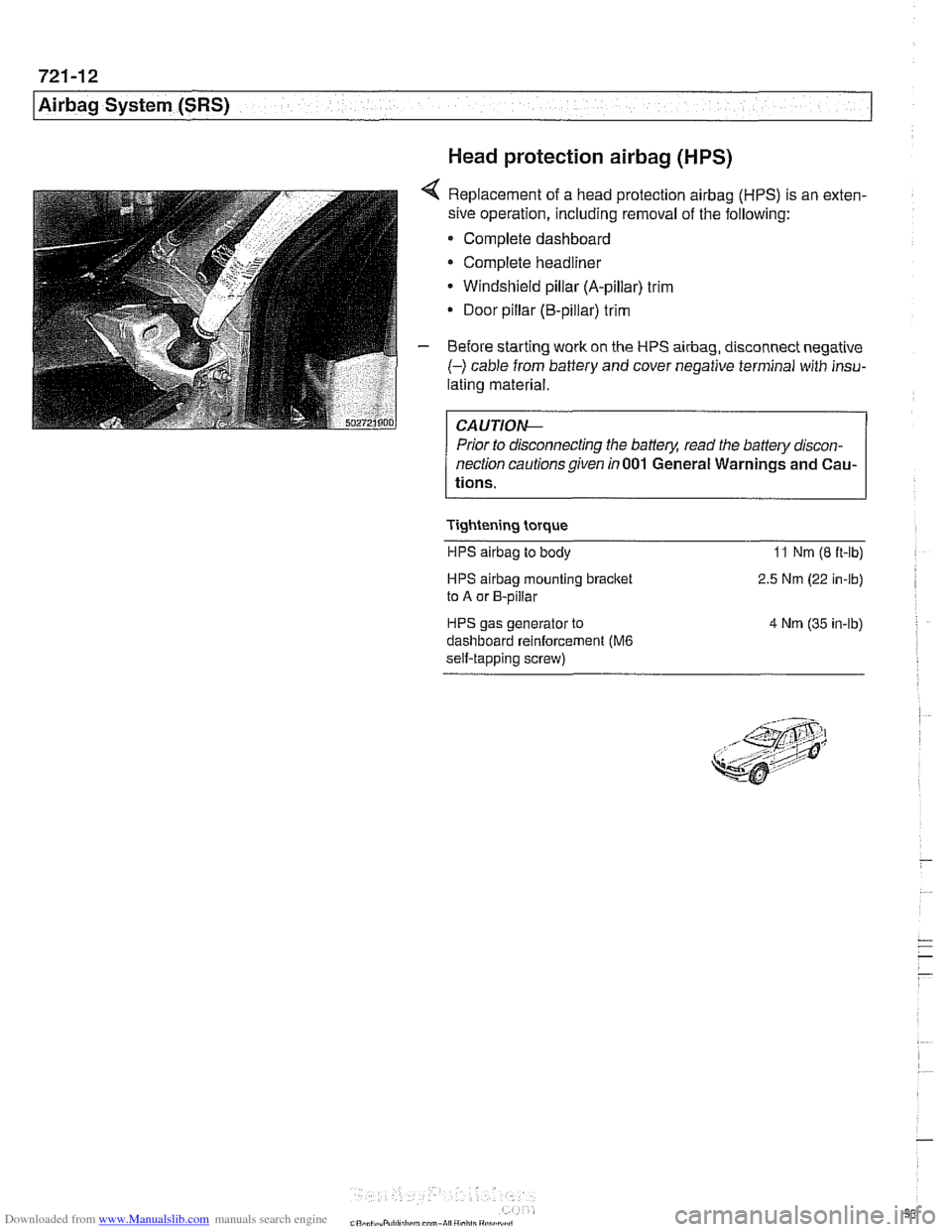
4 Replacement of a head protection airbag (HPS) is an exten-
sive operation, including removal of the following:
Complete dashboard
Complete headliner
Windshield pillar (A-pillar) trim
Door pillar (B-pillar) trim
- Before starting work on the HPS airbag, disconnect negative
(-) cable from battery and cover negative terminal with insu-
lating material.
Prior to disconnecting the battery, read the battery discon-
nection cautionsgiven in001 General Warnings and Cau-
tions.
Tightening torque HPS
airbag to body 11 Nm (8 ft-lb)
HPS airbag mounting bracket
to A or B-pillar
HPS gas generator to
dashboard reinforcement
(M6
self-tapping screw) 2.5
Nm (22 in-lb)
4 Nm (35 in-lb)