Complete manual download BMW 528i 1998 E39 Service Manual
[x] Cancel search | Manufacturer: BMW, Model Year: 1998, Model line: 528i, Model: BMW 528i 1998 E39Pages: 1002
Page 491 of 1002
Downloaded from www.Manualslib.com manuals search engine
Fuel Tank and Fuel pump/
- Remove suction hose from tank filler neck carefully to avoid
damaging filler neck baffle plate.
CAUTION-
After finishing repairs but before starling engine, be sure
there is at least
5 liters (1.5 gallons) of fuel in tanlc. The fuel
pump will be damaged if run without fuel.
Fuel tank, removing and installing
- Remove fuel tank filler cap and drain tank as described
earlier.
- Disconnect negative cable from battery.
CAUTION-
Prior to disconnecting the battea read the battery discon-
nection cautions given in
001 General Cautions and
Warnings.
- Remove rear seat bottom cushion. Peel forward lip of carpet
from beneath seat cushion and carefully peel back insulation
to expose fuel tank access cover on left and right sides. Re-
move covers.
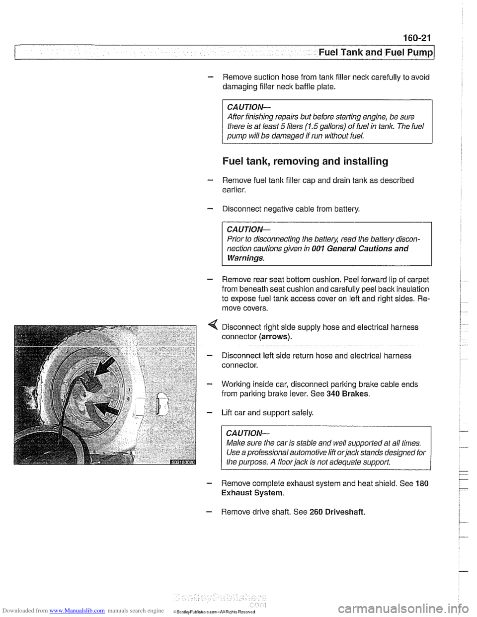
Disconnect right side supply hose and
electr~cal harness
connector (arrows).
D~sconnect left side return hose and electrical harness
connector.
Working inside car, disconnect parking
bralte cable ends
from parking brake lever. See
340 Brakes.
Lift car and support safely.
Make sure the car is stable and
we/ supported at all times.
Use a professional automotive lift
orjack stands designed for
the purpose. A floorjaclc is not adequate support.
- Remove complete exhaust system and heat shield. See 180
Exhaust System.
- Remove drive shaft. See 260 Driveshaft
Page 524 of 1002
Downloaded from www.Manualslib.com manuals search engine
180-2
Exhaust System
The exhaust system is designed to be maintenance free, al-
though regular inspection is warranted due to the harsh oper-
ating conditions. Under normal conditions, the catalytic
converter does not require replacement unless it is damaged.
New fasteners, clamps, rubber mounts and gaskets should
be used when replacing exhaust components.
A liberal appli-
cation of penetrating oil to the exhaust system nuts and bolts
in advance may make removal easier.
WARNING -
The exhaust system and catalytic converter operate at
very high temperatures. Allow components to cool before
servicing. Wear protective clothing to prevent burns.
Do not use flammable chemicals near a hot
cataiyiic
converter.
Corroded exhaust system components crumble easily
and often have exposed sharp edges. To avoid injury,
wear eye protection and heavy gloves when working
Exhaust system, removing and installing
The removal and installation procedures given here are gen-
eral procedures for all models. The removal of the exhaust
system as a complete unit is recommended. Once the com-
plete system is removed from the car, individual pipes and
mufflers can be more easily replaced.
WARNING-
Exhaust gases are colorless, odorless, and very toxic. Run
the engine only in a well-ventilated area. Immediately repair
any
leaks in the exhaust system or structural damage to the
car body that
might allow exhaust gases to enter the passen-
ger compartment.
CAUTION-
Use care not to drag or bang oxygen sensors. Oxygen sen-
sors can be easily ruined.
Page 548 of 1002
Downloaded from www.Manualslib.com manuals search engine
21 0-6
1 Clutch
Hydraulic system, bleeding
(using
BMW special tool 21 5 030)
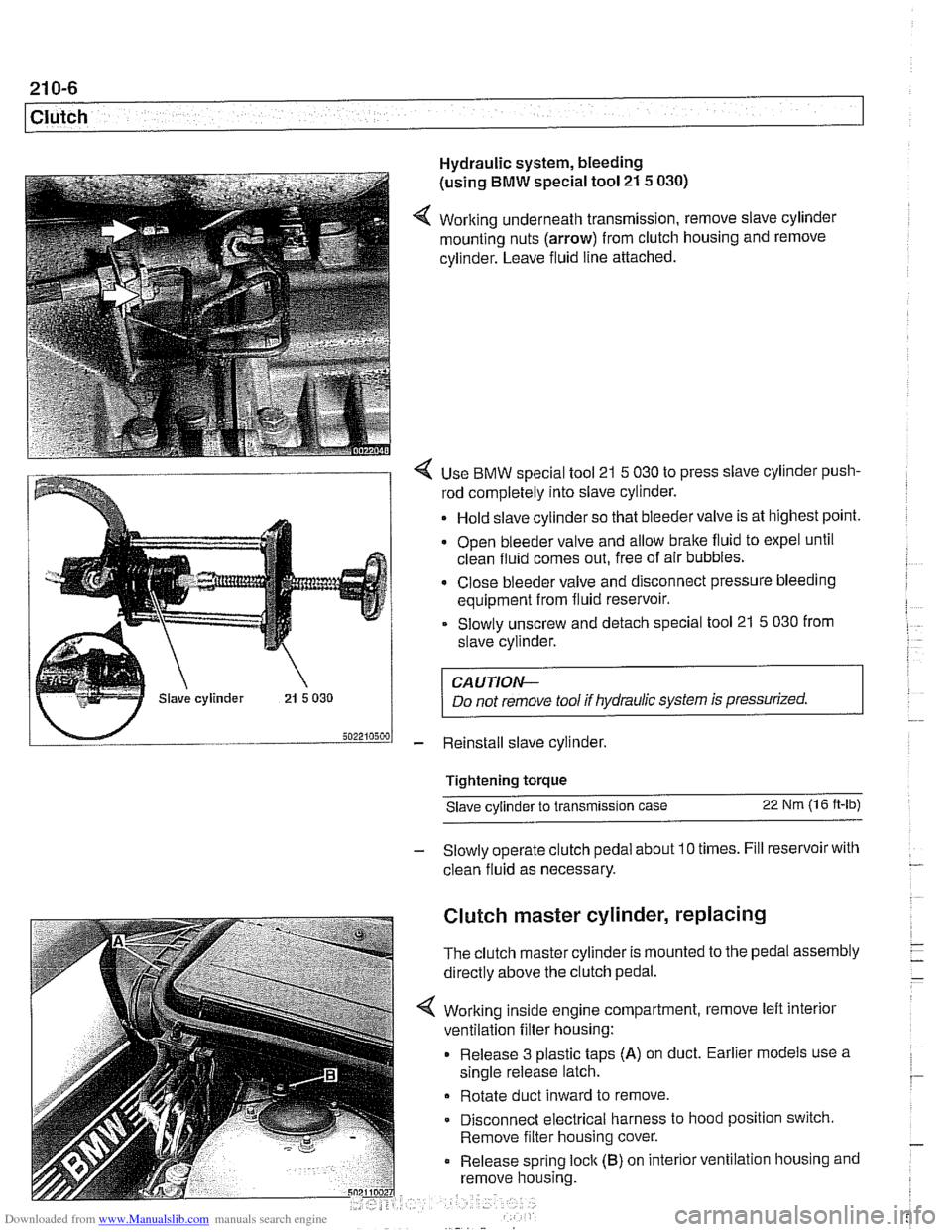
4 Working underneath transmission, remove slave cylinder
mounting nuts (arrow) from clutch housing and remove
cylinder. Leave fluid line attached.
4 Use BMW special tool 21 5 030 to press slave cylinder push-
rod completely into slave cylinder.
Hold slave cylinder so that bleeder valve is at highest point.
Open bleeder valve and allow brake fluid to expel until
clean fluid comes out, free of air bubbles.
* Close bleeder valve and disconnect pressure bleeding
equipment from fluid reservoir.
Slowly unscrew and detach special tool 21
5 030 from
slave cylinder.
CAUTION-
Do not remove tool if hydraulic system is pressurized.
- Reinstall slave cylinder.
Tightening torque Slave cylinder to transmission case
22 Nm (1 6 ft-lb)
- Slowly operate clutch pedal about 10 times. Fill reservoir with
clean fluid as necessary.
Clutch master cylinder, replacing
The clutch master cylinder is mounted to the pedal assembly
directly above the clutch pedal.
Working inside engine compartment, remove left interior
ventilation filter housing:
Release 3 plastic taps
(A) on duct. Earlier models use a
single release latch.
Rotate duct inward to remove
Disconnect electrical harness to hood position switch.
Remove filter housing cover.
Release spring
loclc (B) on interior ventilation housing and
remove housing.
Page 600 of 1002
Downloaded from www.Manualslib.com manuals search engine
250-2
I Gearshift Linkage
This repair group covers transmission gearshift and linkage service for both manual and automatic transmission
equipped vehicles.
To gain access to the complete gearshift mechanism it is
necessary to remove the exhaust system and the driveshaft
as described in
180 Exhaust System and 260 Driveshaft.
NOTE-
In models with automatic transmission, the electronic immo-
bilizer
(EWS) prevents starter operation unless the gear po-
sition is Park or Neutral.
Special tools
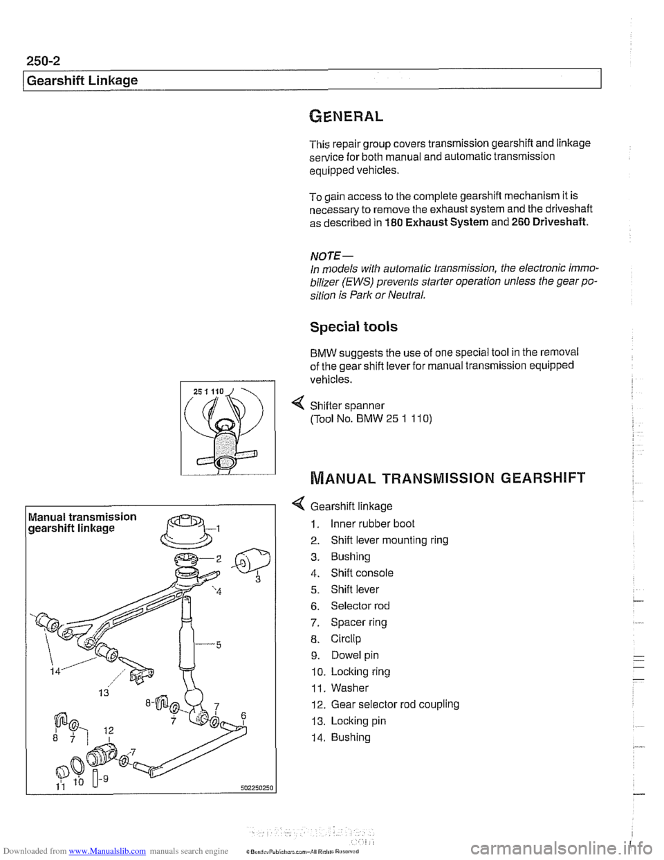
BMW suggests the use of one special tool in the removal
of the gear shift lever for manual transmission equipped
I I vehicles.
Manual transmission
gearshift linkage
--
4 Gearshift linkage
1. Inner rubber boot
2. Shift lever mounting ring
3. Bushing
4. Shift console
5. Shift lever
6. Selector rod
7. Spacer ring
8. Circlip
9. Dowel pin
10. Locking ring
11. Washer
12. Gear selector rod coupling
13. Locking pin
14. Bushing
4 Sh~fter spanner
(Tool No. BMW
25 1 11 0)
MANUAL TRANSMISSION GEARSHIFT
Page 601 of 1002
Downloaded from www.Manualslib.com manuals search engine
Gearshift ~inkaael
Gearshift lever, removing
(manual transmission)
Use the accompanying illustration as a guide when removing
and installing the gearshift linkage.
- Remove shift knob by pulling knob straight off shift lever.
NOTE-
Pull up on the shift knob with about 90 lbs. of force. Do not
twist
knob or locating key can be damaged.
- Squeeze sides of shift boot to unclip from center console.
Pull boot up and off shift lever.
- Remove sound insulation at base of shift lever.
- Raise vehicle to gain access to underside of vehicle.
- --
WARNING-
Male sure the car is stable and well supported at all tfmes.
Use a professional automotwe hft orjaclc stands designed for
the purpose.
A floorjaclc 1s not adequate support.
- Remove complete exhaust system. See 180 Exhaust
System.
- Remove driveshaft. See 260 Driveshaft.
- Support transmission with transmission jack. Remove
crossmember from rear of transmission.
- Lower rear of transmission to access gearshift linkage.
CA UTIOI\C
Tilting the engine to lower the transmission can lead to
damage to various components due to lack of clearance.
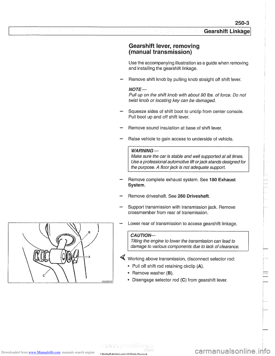
4 Working above transmission, disconnect selector rod:
* Pull off shift rod retaining circlip (A).
Remove washer (6).
Disengage selector rod (C) from gearshift lever.
Page 608 of 1002
Downloaded from www.Manualslib.com manuals search engine
260-2
1 Driveshaft
This repair group covers repair and replacement of the
driveshaft and driveshaft components.
Driveshaft repairs consist of replacement of front flex-disc.
center mount or rear
CV joint. If the driveshaft joint is defec-
tive, replace the complete driveshaft.
Drive axle repairs are covered in
331 Final Drive
Special tools
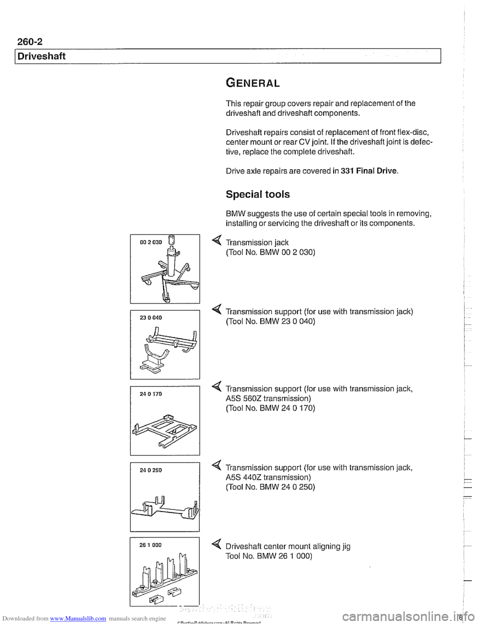
BMW suggests the use of certain special tools in removing,
installing or servicing the driveshaft or its components.
4 Transmission jack
(Tool No. BMW 00 2 030)
4 Transmission support (for use with transmission jack)
/ (Tool NO. BMW 23 0 040)
24 0 170
1
4 Transmission support (for use with transmission jack,
A5S 560Z transmission)
(Tool No. BMW 24
0 170)
24 0 250
I
4 Transmission support (for use with transmission jack,
A5S
4402 transmission)
(Tool No. BMW 24
0 250)
4 Drlveshaft center mount allgnlng yg
Tool No. BMW 26 1 000)
Page 614 of 1002
Downloaded from www.Manualslib.com manuals search engine
-.- .
/ Driveshaft Driveshaft, removing
CAUTION-
. Be sure the wheels are off the ground before removing the
driveshak Set the parl(ing brake before removing the
driveshaft.
Once the driveshaft has been removed, the vehicle can
roll regardless of whether the transmission is in gear or
not.
The driveshaft is mounted to the transmission and final
drive
with self-locliing nuts. These nuts are designed to
be used only once and should be replaced during reas-
sembly.
Remove complete exhaust system. See
180 Exhaust
System.
- Remove exhaust heat shields.
- Support transmission with transmission jack.
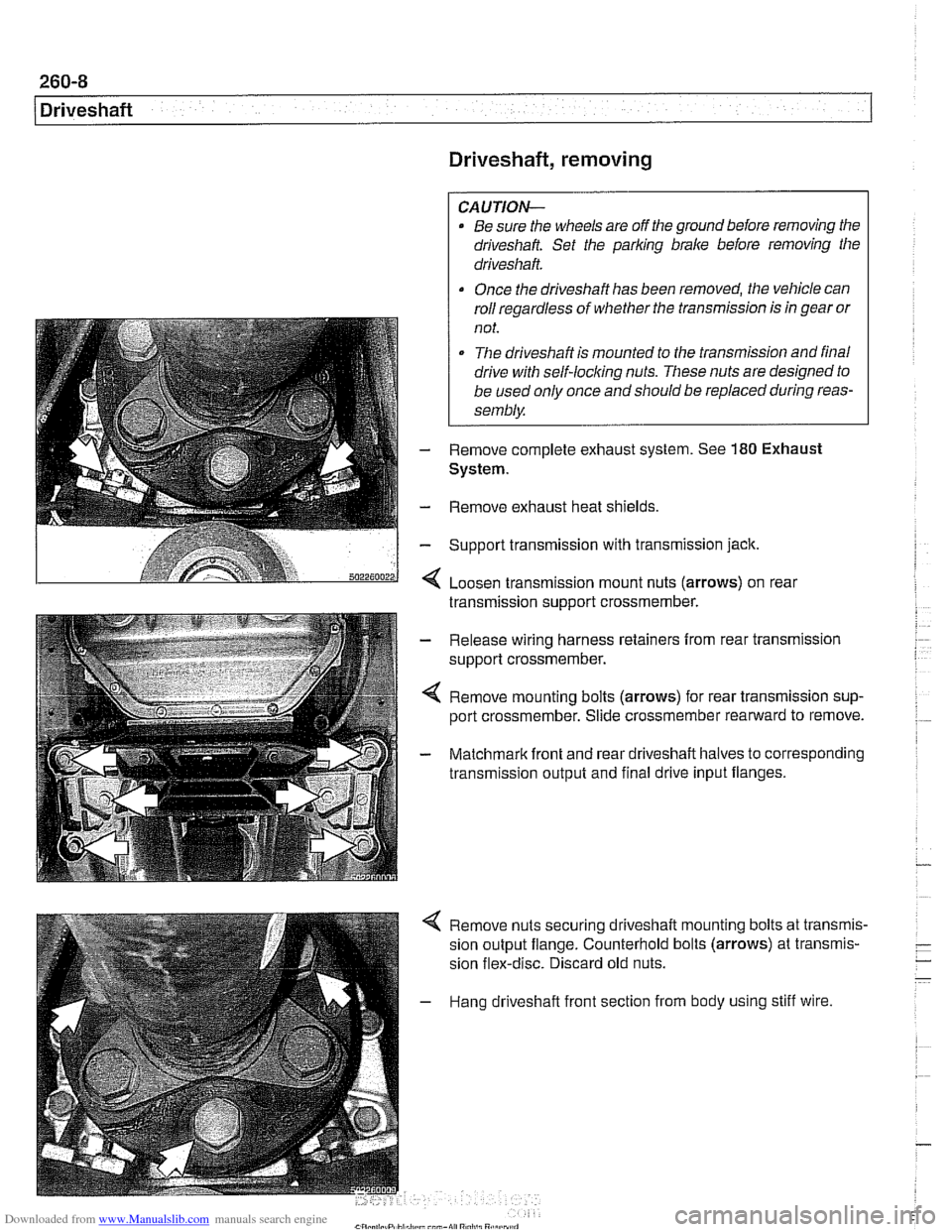
< Loosen transmission mount nuts (arrows) on real
transmission support crossmember.
- Release wiring harness retainers from rear transmission
support crossmember.
< Remove mounting bolts (arrows) for rear transmission sup-
port crossmember. Slide crossmember rearward to remove.
- Matchmark front and rear driveshaft halves to corresponding
transmission output and final drive input flanges.
4 Remove nuts securing driveshaft mounting bolts at transmis-
sion output flange. Counterhold bolts (arrows) at transmis-
sion flex-disc. Discard old nuts.
- Hang driveshaft front section from body using stiff wire.
Page 620 of 1002
Downloaded from www.Manualslib.com manuals search engine
260-14
Driveshaft
Constant velocity (CV) joint, replacing
The CV joint at the rear of the driveshaft is available from
BMW as a separate part.
- Remove complete driveshaft as described earlier in this
section.
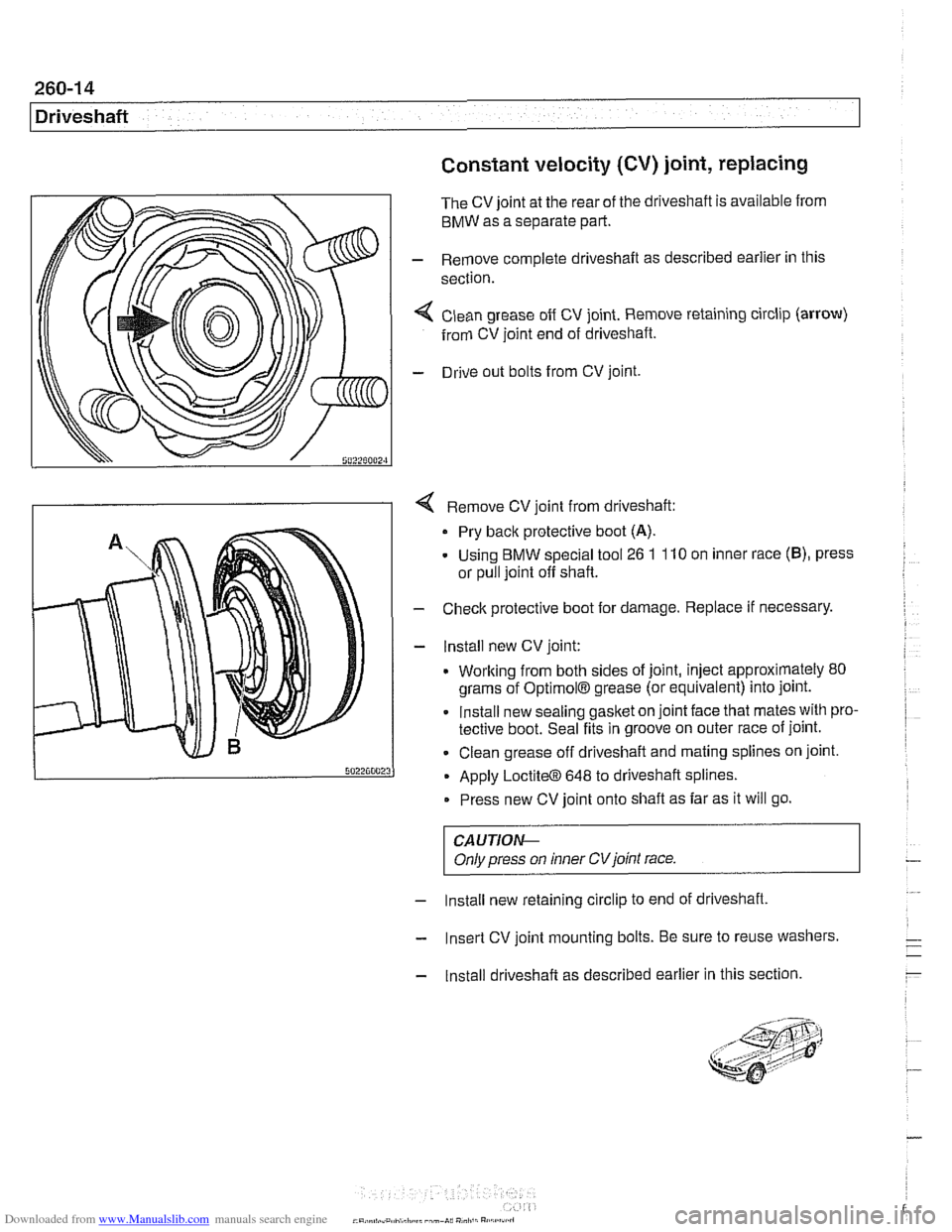
< Clean grease off CV joint. Remove retaining circlip (arrow)
from CV joint end of driveshaft.
- Drive out bolts from CV joint.
4 Remove CV joint from driveshaft:
Pry back protective boot
(A).
- Using BMW special tool 26 1 110 on inner race (B), press
or pull joint off shaft.
- Check protective boot for damage. Replace if necessary.
- lnstall new CV joint:
. Working from both sides of joint, inject approximately 80
grams of
OptimolB grease (or equivalent) into joint.
Install new sealing gasket on joint face that mates with pro-
tective boot. Seal fits in groove on outer race of joint.
Clean grease off driveshaft and mating splines on joint.
Apply
LoctiteO 648 to driveshaft splines.
Press new CV joint onto shaft as far as it will go.
CAUTIOI\C
Only press on inner CVjoint race.
- Install new retaining circlip to end of driveshaft,
- Insert CV joint mounting bolts. Be sure to reuse washers.
- Install driveshaft as described earlier in this section.
Page 644 of 1002
Downloaded from www.Manualslib.com manuals search engine
31 0-8
Front Suspension
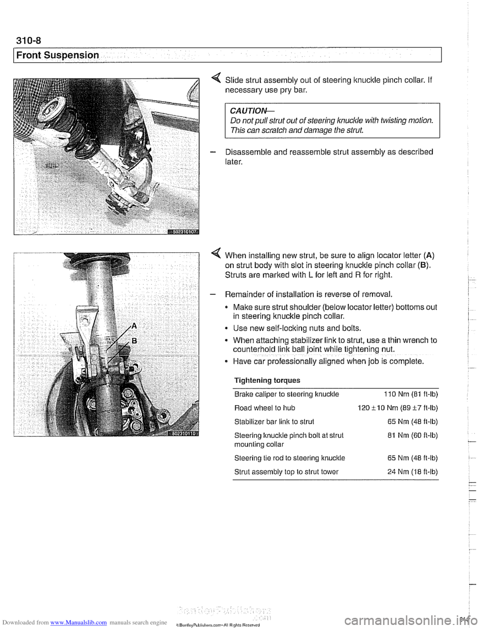
Slide strut assembly out of steering lknucltle pinch collar. If
necessary use pry bar.
CA UTIOI\C
Do notpullstrut out of steering knuckle with twisting motion.
This can scratch and damage the strut.
Disassemble and reassemble strut assembly as described
later.
When installing new strut, be sure to align locator letter (A)
on strut body with slot in steering
lknuckle pinch collar (6).
Struts are marked with L for left and R for right.
Remainder of installation is reverse of removal.
Make sure strut shoulder (below locator letter) bottoms out
in steering knuckle pinch collar.
Use new self-locking nuts and bolts.
When attaching stabilizer
lrnk to strut, use a thin wrench to
counterhold
link ball joint while t~ghtening nut.
- Have car professionally al~gned when job IS complete.
Tightening torques
Brake caliper to steering knuckle
110 Nm (81 ft-ib)
Road wheel to hub 120 ti0 Nm (89 t7 ft-lb)
Stabilizer bar
link to strut 65 Nm (48 It-lb)
Steering knucltle pinch bolt at strut 81 Nm (60 It-lb) - mountlng collar
Steering tle rod to steerlng knuckle 65 Nm (48 it-lb)
Strut assembly top to strut tower 24 Nm (18 it-lb)
- - -
Page 646 of 1002
Downloaded from www.Manualslib.com manuals search engine
31 0-1 0
Front Suspension
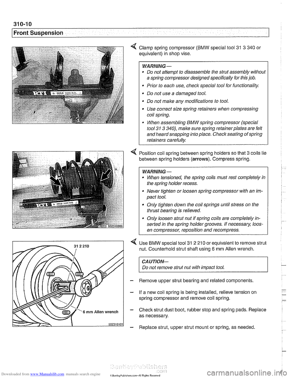
4 Clamp spring compressor (BMW special tool 31 3 340 or
equivalent) in shop vise.
WARNING-
* Do not attempt to disassemble the strut assembly without
a spring compressor designed specifically for this job.
Prior to each use,
checlc special tool for functionality.
Do not use a damaged tool.
Do not make any modifications to tool. Use correct size spring retainers when compressing
coil spring.
I When assembling BMW spring compressor (special
tool
31 3 340), make sure spring retainerplates are felt
and heard snapping into place. Check seating of spring
retainers carefully.
Position coil spring between spring holders so that
3 coils lie
between spring holders
(arrows). Compress spring.
WARNING -
When tensioned, the spring coils must rest completely in
the spring holder recess.
Never tighten or loosen spring compressor with an im-
pact tool.
Only tighten down the coil springs until stress on the
thrust bearing is relieved.
a Only loosen strut nut if spring coils are completely in-
serted in the spring holder grooves. If
necessarx loos-
en compressor, reposition and recompress.
Use
BMW special tool 31 2 21 0 or equivalent to remove strut
nut. Counterhold strut shaft using
6 mm Allen wrench.
CAUTION-
Do not remove strut nut with impact tool.
Remove upper strut bearing and related components.
If a new coil spring is being installed, relieve tension on
spring compressor and remove coil spring.
Check strut dust boot, rubber stop and spring pads. Replace
as necessary.
Replace strut, upper strut mount or spring, as needed