EWS BMW 528i 1998 E39 Owner's Manual
[x] Cancel search | Manufacturer: BMW, Model Year: 1998, Model line: 528i, Model: BMW 528i 1998 E39Pages: 1002
Page 301 of 1002
Downloaded from www.Manualslib.com manuals search engine
Cp-- Camshaft -- Timing Chain
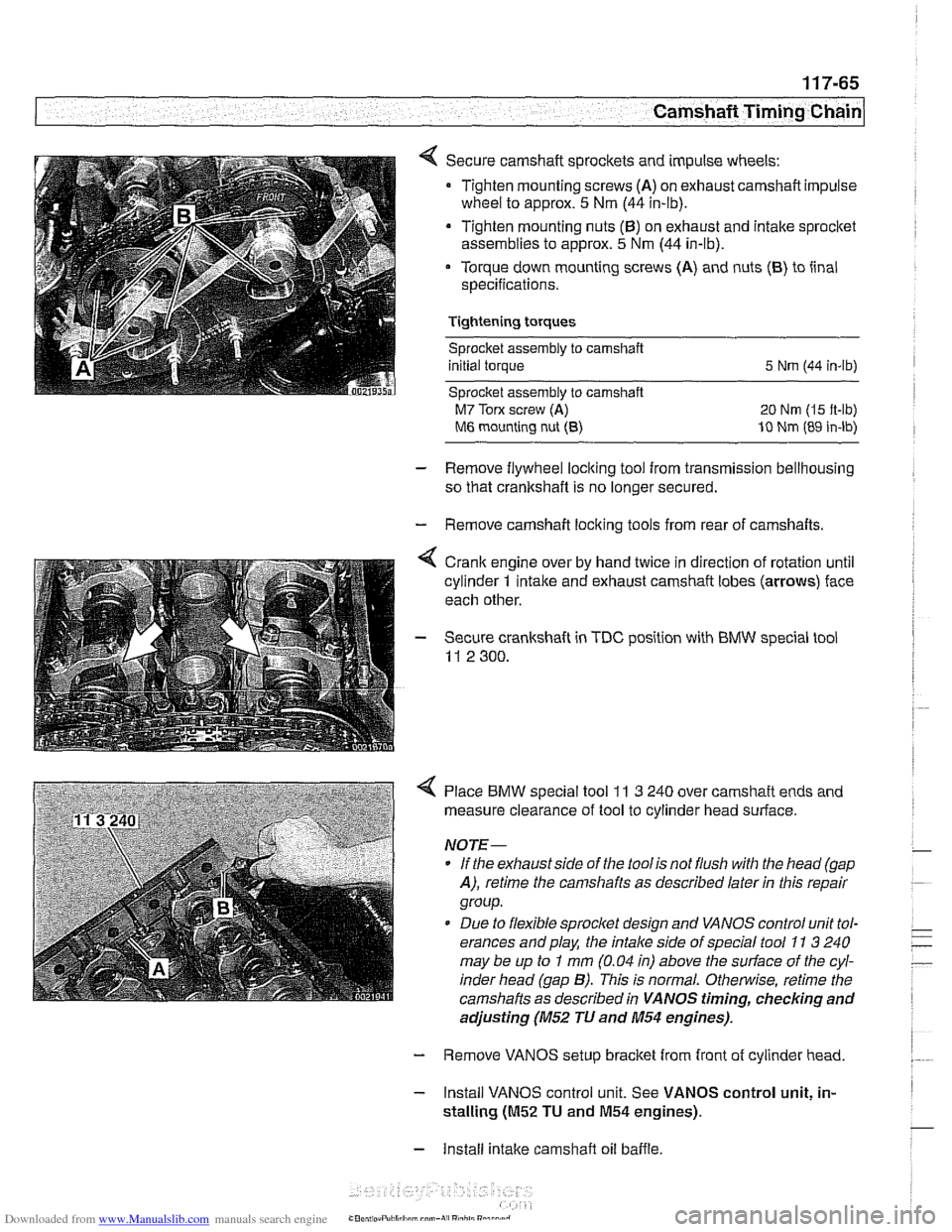
Secure camshaft sprockets and impulse wheels:
Tighten mounting screws
(A) on exhaust camshaft impulse
wheel to approx.
5 Nm (44 in-lb).
Tighten mounting nuts
(6) on exhaust and intake sprocket
assemblies to approx.
5 Nm (44 in-lb).
Torque down mounting screws (A) and nuts
(6) to iinal
specifications.
Tightening torques Sprocket assembly
to camshaft
initial torque
5 Nrn (44 in-lb)
Sprocket assembly to camshaft
M7 Torx screw (A) 20 Nm (I5 it-lb)
M6 mounting nut (8) 10 Nm (89 in-lb)
- Remove flywheel locking tool from transmission bellhousing
so that crankshaft is no longer secured.
- Remove camshaft loclting tools from rear of camshafts.
4 Crank engine over by hand twice in direction of rotation until
cylinder
1 intake and exhaust camshaft lobes (arrows) face
each other.
- Secure crankshaft in TDC position with BMW special tool
11 2 300.
4 Place BMW special tool 11 3 240 over camshaft ends and
measure clearance of tool to cylinder head surface.
NOTE-
* If the exhaust side of the tool is not flush with the head (gap
A), retime the camshafts as described laler in this repair
group.
Due to flexible sprocket design and VANOS control unit tol-
erances and play, the
intake side of special tool 71 3 240
may be up to
I mm (0.04 in) above the suriace of the cyl-
inder head (gap
B). This is normal. Otherwise, retime the
camshafts as described in
VANOS timing, checking and
adjusting (M52 TU and 11154 engines).
- Remove VANOS setup bracket from front of cylinder head
- Install VANOS control unit. See VANOS control unit, in-
stalling
(01152 TU and M54 engines).
- Install intake camshaft oil baffle
Page 311 of 1002
Downloaded from www.Manualslib.com manuals search engine
Camshaft Timing Chain1
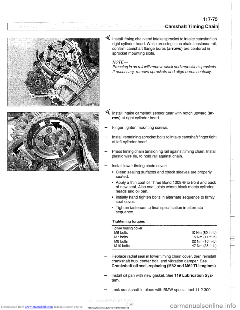
lnstall timing chain and intake sprocket to intake camshaft on
right cylinder head. While pressing in on chain tensioner rail,
confirm camshaft flange bores (arrows) are centered in
sprocket mounting slots.
NOTE-
Pressing in on rail will remove slack and reposition sprockets.
If
necessarx remove sproclets and align bores centrally.
lnstall intake camshaft sensor gear with notch upward (ar-
row) at right cylinder head.
- Finger tighten mounting screws.
- lnstall remaining sprocket bolts to intake camshaft finger tight
at left cylinder head.
- Press timing chain tensioning rail against timing chain. lnstall
plastic wire
tie, to hold rail against chain.
- lnstall lower timing chain cover:
Clean sealing surfaces and check sleeves are properly
seated.
Apply a thin coat of Three Bond 1209
8 to front and back
of new seal. Also coat joints where block meets cylinder
heads and oil pan.
Initially hand tighten bolts in alternate sequence to firmly
seat cover.
Tighten fasteners to final specification in alternate
sequence.
Tightening torques Lower timing cover
M6 bolts 10 Nrn (89 in-lb)
M7 bolts 15 Nm (1 1 ft-lb)
ME bolts 22 Nm (1 6 ft-lb)
M10 bolts 47 Nm (35 ft-lb)
- Replace radial seal in lower timing chain cover, then reinstall
crankshaft hub, center bolt, and vibration damper. See
Crankshaft oil seal, replacing
(M62 and M62 TU engines).
- lnstall oil pan with new gasket. See 119 Lubrication Sys-
tem.
- Lock crankshaft in place with BMW special tool 11 2 300
Page 332 of 1002
Downloaded from www.Manualslib.com manuals search engine
119-12
Lubrication System 1
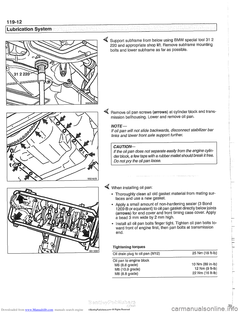
4 Support subframe from below using BMW special tool 31 2
220 and appropriate shop lift. Remove
subframe mounting
bolts and lower
subframe as far as possible.
Remove oil pan screws (arrows) at cylinder block and trans-
mission bellhousing. Lower and remove oil pan.
NOTE-
If oil pan will not slide backwards, disconnect stabilizer bar
links and lower front axle support further.
If the oil pan does not separate easily from the engine cylin-
der
block, a few taps with a rubber malletshould breakit free.
Do not
pry the oil pan loose.
When installing oil pan: Thoroughly clean all old gasket material from mating sur-
faces and use a new gasket.
Apply a small amount of non-hardening sealer
(3 Bond
12098 or equivalent) to oil pan gasket directly below joints
(arrows) for end cover and front timing case cover. Apply
a bead
3 mm wide by 2 mm high.
Install all oil pan bolts finger tight. Tighten oil pan bolts to-
ward front of engine first, then pan bolts at transmission
end.
Tightening
torques
Oil drain plug to oil pan (M12) 25 Nm (18 ft-lb)
Oil pan to engine block
MG (8.8 grade)
MG (10.9 grade)
M8 (8.8 grade)
10 Nm (89 In-lb)
12 Nm (9 ft-lb)
22 Nrn (16 R-lb)
Page 362 of 1002
Downloaded from www.Manualslib.com manuals search engine
I Ignition System
Camshaft position sensors
The camshaft position sensors are used by the englne man-
agement system for VANOS control, sequential fuel injection
and knock control.
Intake camshaft position sensor, replacing
(M52,M52 TU
and M54 engines)
- Make certain ignition has been turned off.
- Remove plastic cover from above fuel injectors by prying off
bolt covers and removing cover mounting bolts.
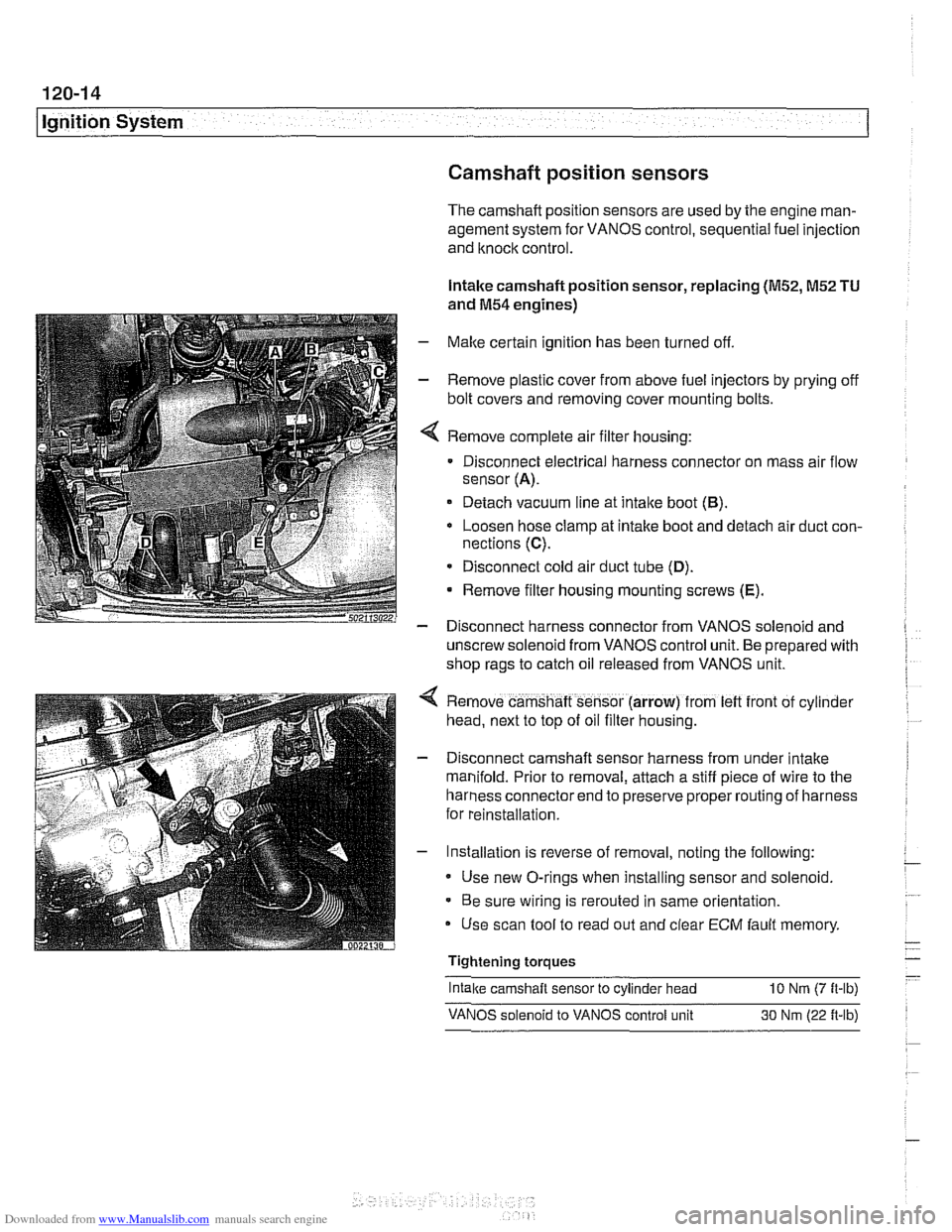
Remove complete air filter housing:
Disconnect electrical harness connector on mass air flow
sensor
(A).
Detach vacuum line at intake boot (B).
Loosen hose clamp at intake boot and detach air duct con-
nections
(C).
* Disconnect cold air duct tube (D).
Remove filter housing mounting screws (E).
- Disconnect harness connector from VANOS solenoid and
unscrew solenoid from VANOS control unit. Be prepared with
shop rags to catch oil released from VANOS unit.
Remove camshaft sensor (arrow) from
left front of cyl~nder
head, next to top of oil filter housing.
Disconnect camshaft sensor harness from under intake
manifold. Prior to removal, attach a stiff piece of wire to the
harness connector end to preserve proper routing of harness
for reinstallation.
Installation is reverse of removal, noting the following:
Use new O-rings when installing sensor and solenoid.
Be sure wiring is rerouted in same orientation.
Use scan tool to read out and clear
ECM fault memory
Tightening torques
-
Intake camshaft sensor to cylinder head 10 Nrn (7 ft-lb)
VANOS solenoid to VANOS control unit 30 Nm (22 ft-lb)
Page 369 of 1002
Downloaded from www.Manualslib.com manuals search engine
Battery, Starter, ~lternatorl
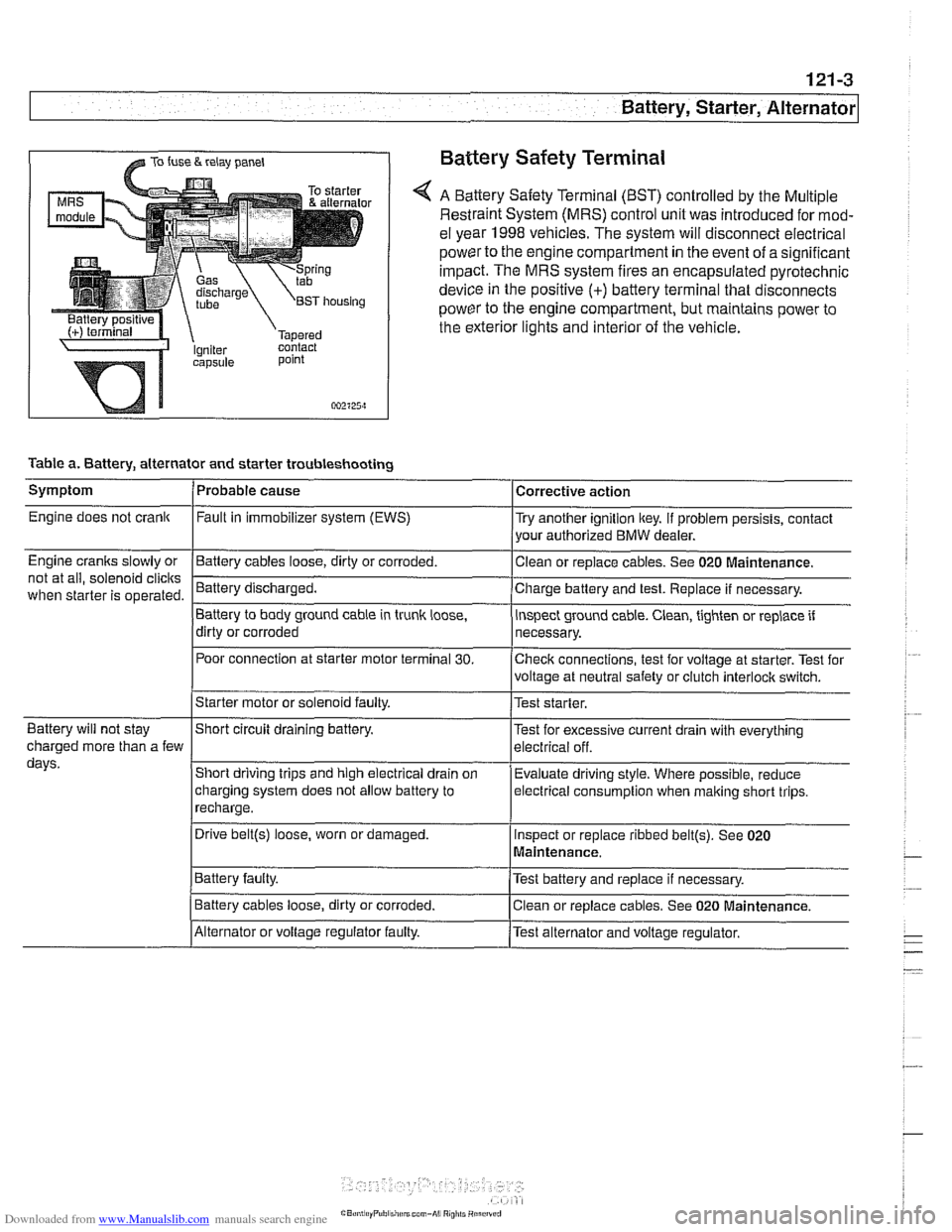
@ TO fuse & relay panel Battery Safety Terminal
A Battery Safety Terminal (BST) controlled by the Multiple
Restraint System (MRS) control unit was introduced for mod-
el year 1998
vehicles. The system will disconnect electrical
power to the engine compartment
in the event of a significant
impact. The MRS system fires an encapsulated pyrotechnic
device
in the positive (+) battery terminal that disconnects
power to the engine compartment, but maintains power to
the exterior lights and interior of the vehicle.
point
002125~1
Table a. Battery, alternator and starter troubleshooting
1-
/Starter motor or solenoid faulty. l~est starter.
Symptom
Engine does not crank
Engine cranks slowly or
not at all, solenoid
clicits
when starter is operated.
I I
Battery will not stay IShort circuit draining battery. l~est for excessive current drain with everything
Probable cause
Fault
in immobilizer system (EWS)
-Clean Battery cables loose, dirty or corroded.
Battery discharged.
Battery to body ground cable in trunk
loose,
dirty or corroded
Poor connection at starter motor terminal
30.
Corrective action
Try another ignition key. If problem persists, contact
your authorized BMW dealer.
or replace cables. See 020
~aintenance.
Charge battery and test. Replace if necessary.
inspect ground cable. Clean, tighten or replace if
necessary.
Checlc connections, test for voltage at starter. Test for
voltage at neutral safety or clutch
interloclc switch.
charged more than a few
days.
I~atter~ faulty. /Test battery and replace if necessary.
Short driving trips and high electrical drain
on
charging system does not allow battery to
recharge.
. I
I Battery cables loose, dirty or corroded. Iclean or replace cables. See 020 Maintenance.
Evaluate driving
style. Where possible, reduce
electrical
consumption when malting short trips.
Drive
belt@) loose, worn or damaged.
IAlternator or voltage regulator faulty. /Test alternator and voltage regulator.
Inspect
or replace ribbed
belt@). See 020
Maintenance.
Page 385 of 1002
Downloaded from www.Manualslib.com manuals search engine
Battery, Starter, Alternator
- Installation is reverse of removal, noting the following:
Replace alternator rubber sealing O-ring.
* Fill and bleed cooling system as described in 170 Radiator
and Cooling System.
Tightening torques
Fan clutch to coolant pump
with
BMW special tool 11 5 040 30 Nm (22 ft-lb)
without
BMW special tool 11 5 040 40 Nm (29 ft-lb)
Terminal 30 (Bc) wire to alternator (ME) 13 Nm (10 ft-lb)
STARTER
Starter troubleshooting
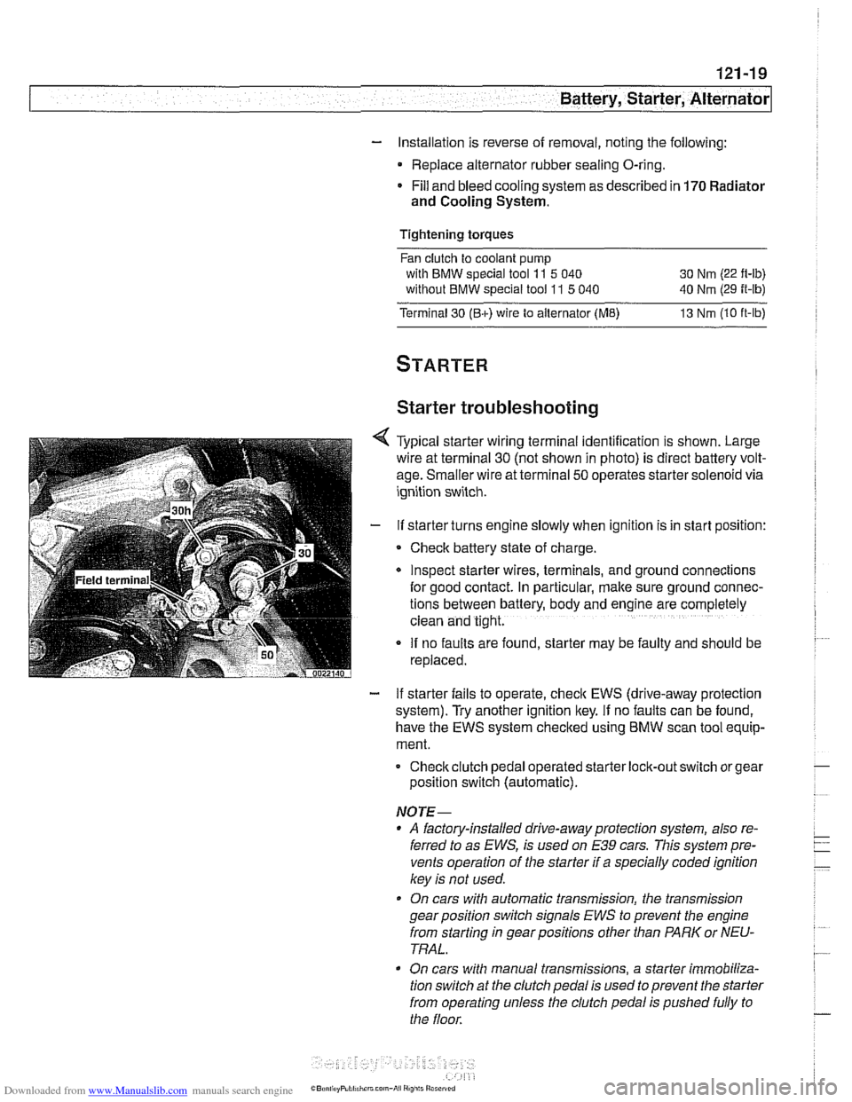
Typical starter wiring terminal identification is shown. Large
wire at terminal
30 (not shown in photo) is direct battery volt-
age. Smaller wire at terminal
50 operates starter solenoid via
ignition switch.
If starter turns engine slowly when ignition is in start position:
Check battery state of charge.
Inspect starter wires, terminals, and ground
connectlons
for good contact. In particular, make sure ground connec-
tions between battery, body and
englne are completely
clean and tight.
If no faults are found, starter may be faulty and should be
replaced.
- If starter fails to operate, check EWS (drive-away protection
system). Try another ignition key.
If no faults can be found,
have the EWS system checked using
BMW scan tool equip-
ment.
Checkclutch pedal operated
starter lock-out switch or gear
position switch (automatic).
NOTE-
* A factory-installed drive-away protection system, also re-
ferred to as
EWS, is used on E39 cars. This system pre-
vents operation of the starter if a specially coded ignition
key is not used.
On cars with automatic transmission, the transmission
gear position switch signals
EWS to prevent the engine
from starting in gear positions other than PARK or NEU-
TRAL.
On cars with manual transmissions, a starter immobiliza-
tion switch
at the clutch pedal is used to prevent the starter
from operating unless the clutch pedal is pushed fully to
the floor.
Page 386 of 1002
Downloaded from www.Manualslib.com manuals search engine
I Battery, Starter, Alternator
- Check for battery voltage at terminal 50 of starter motor with
key in start position. If voltage is not present, check wiring be-
tween ignition switch and starter terminal. Check the EWS
system and other inputs that disrupt terminal
56 to the start-
er. See ELE Electrical
Wiring Diagrams. If voltage is
present and no other visible wiring faults can be found, prob-
lem is most likely in starter motor.
Starter, removing and installing
(6-cylinder engine)
The starter is removed from below. Access to starter bolts is
difficult. Be sure to have the proper tools on hand before pro-
ceeding.
NOTE-
Access to the starter wiring is very limited. Forbetteraccess,
it may be necessary to remove the intake manifold.
- Disconnect negative (-) battery cable.
CAUTIOI\C
Prior to disconnecting the battern read the baltery discon-
nection cautions
in OOlGeneral Cautions and Warnings.
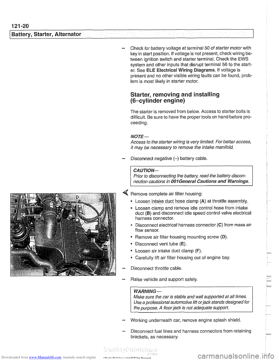
Remove complete air filter hous~ng:
Loosen intake duct hose clamp (A) at throttle assembly.
Loosen clamp and remove idle control hose from intake
duct
(B) and disconnect idle speed control valve electrical
harness connector.
Disconnect electrical harness connector
(C) from mass air
flow sensor.
Remove air filter housing mounting screw (D)
Disconnect vent tube
(E).
Loosen air intake duct clamp (F).
Carefully lift air filter housing out of engine bay.
Disconnect throttle cable.
Raise vehicle and support safely.
WARNING-
Make sure the car is stable and well supported at all times.
Use a professional automotive
lift orjack stands designed for
the purpose. A
floorjaclc is not adequate support
- Working underneath car, remove engine splash shield
- Disconnect fuel lines and harness connectors from retaining
brackets, as necessary.
Page 389 of 1002
Downloaded from www.Manualslib.com manuals search engine
121-23
Battery, Starter, ~lternatorl
Solenoid switch, removing and installing
- Remove starter as described previously.
- Disconnect field winding strap between starter motor and
solenoid switch.
NOTE-
If the field winding strap is damaged or burned, a new or
rebuilt starter motor is needed.
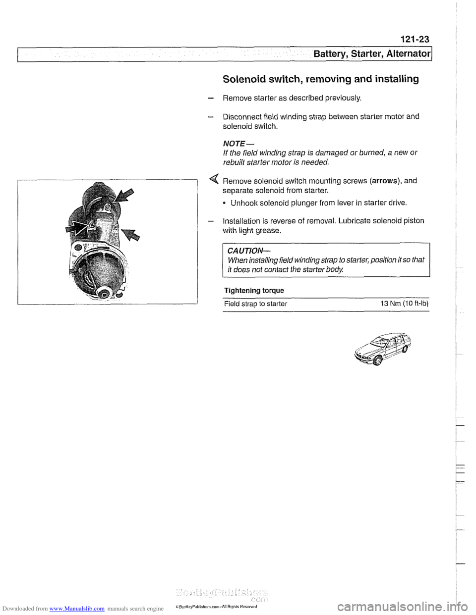
< Remove solenoid switch mounting screws (arrows), and
separate solenoid from starter.
Unhoolc solenoid plunger from lever in starter drive
- Installation is reverse of removal. Lubricate solenoid piston
with light grease.
CAUTION- When installing field winding strap to starter, position
itso that
it does not contact the starter body.
Tightening torque
Field strap to starter
13 Nm (10 ff-lb)
Page 403 of 1002
Downloaded from www.Manualslib.com manuals search engine
130-1 3
Fuel Injection I
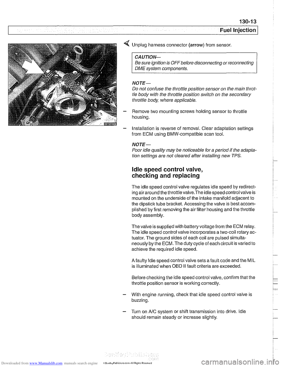
< Unplug harness connector (arrow) from sensor.
CAUTION-
Be sure ignition is OFF before disconnecting or reconnecting
DME system components.
NOTE-
Do not confuse the throttle position sensor on the main Nirot-
tle body with the throttle position switch on the secondary
throttle body, where applicable.
- Remove two mounting screws holding sensor to throttle
housing.
- Installation is reverse of removal. Clear adaptation settings
from ECM using BMW-compatible scan tool.
NOTE-
Poor idle quality may be noticeable for a period if the adapta-
tion settings are not cleared after installing new TPS.
ldle speed control valve,
checking and replacing
The idle speed control valve regulates idle speed by redirect-
inq airaround the throttlevalve.The idlespeed control valve is
mounted on the underside of the intake manifold adjacent to
the dipstick tube bracket. Accessing the valve is best accom-
plished by first removing the air filter housing and the throttle
body assembly.
The valve issupplied with
batteryvoltagefrom the ECM relay.
The idle speed control valve incorporates a two-coil rotary ac-
tuator. The ground sides of each coil are pulsed
sirnulta-
neously by the ECM. The duty cycle of each circuit is varied to
achieve the required idle speed.
Afaulty ldle speed control valve sets afault code and the MIL
is illuminated when
OED II fault criteria are exceeded.
Before checking the idle speed control valve, confirm that the
throttle position sensor is working correctly.
- With engine running, check that idle speed control valve is
buzzing.
- Turn on AIC system or shift transmission into drive. ldle
should remain steady or increase slightly.
Page 409 of 1002
Downloaded from www.Manualslib.com manuals search engine
Fuel Injection I
- As an alternative, harness connector housing can be sepa-
rated so that electrical
checlts can be made from backof con-
nector.
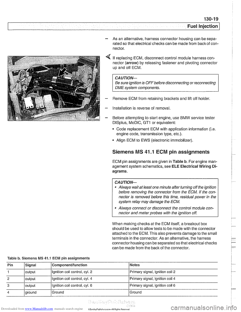
4 If replacing ECM, disconnect control module harness con-
nector (arrow) by releasing fastener and pivoting connector
up and
off ECM.
CAUTION-
Be sure ignition is OFF before disconnecting or reconnecting
DME system components.
- Remove ECM from retaining brackets and lift off holder.
- Installation is reverse of removal.
- Before attempting to start engine, use BMW service tester
DISplus, MoDiC, GTI or equivalent:
- Code replacement ECM with application information (i.e.
engine code, transmission type, etc.).
Align ECM to EWS (electronic immobilizer).
Siemens MS 41.1 ECM pin assignments
ECM pin assignments are given in Table b. For engine man-
agement system schematics, see ELE Electrical Wiring
Di-
agrams.
CAUTION-
a Always wait at least one minute after turning off the ignition
before removing the connector from the
ECM. If the con-
nector is removed before this time, residual power
in the
system relay may damage the
ECM.
Always connect or disconnect the control module con-
nector and meter probes with the ignition
off
When malting checks at the ECM itself, a breakout box
should be used to allow tests to be made with the connector
attached to the ECM. This also prevents damage to the small
terminals in the connector. As an alternative, the harness
connector housing can be separated so that electrical checlts
can be made from the back of the connector.
Table b. Siemens MS
41.1 ECM pin assignments
Pin
1
2
3
4
Signal
output
output
output
qround Componenfffunction
Ignition coil control, cyl. 2
Ignition coil control, cyl. 4
ignition coil control, cyl. 6
Ground Notes
Primary signal,
ignition
coil 2
Primary signal, ignition coil 4
Primary signal, ignition coil 6
Ground