EWS BMW 528i 1998 E39 Service Manual
[x] Cancel search | Manufacturer: BMW, Model Year: 1998, Model line: 528i, Model: BMW 528i 1998 E39Pages: 1002
Page 510 of 1002
Downloaded from www.Manualslib.com manuals search engine
Radiator and Cooling System
Cooling system, bleeding
Trapped air in the cooling system can prevent proper coolant
circulation and overheating. Wheneverthe coolant is drained
and filled, bleed the cooling system to remove trapped air.
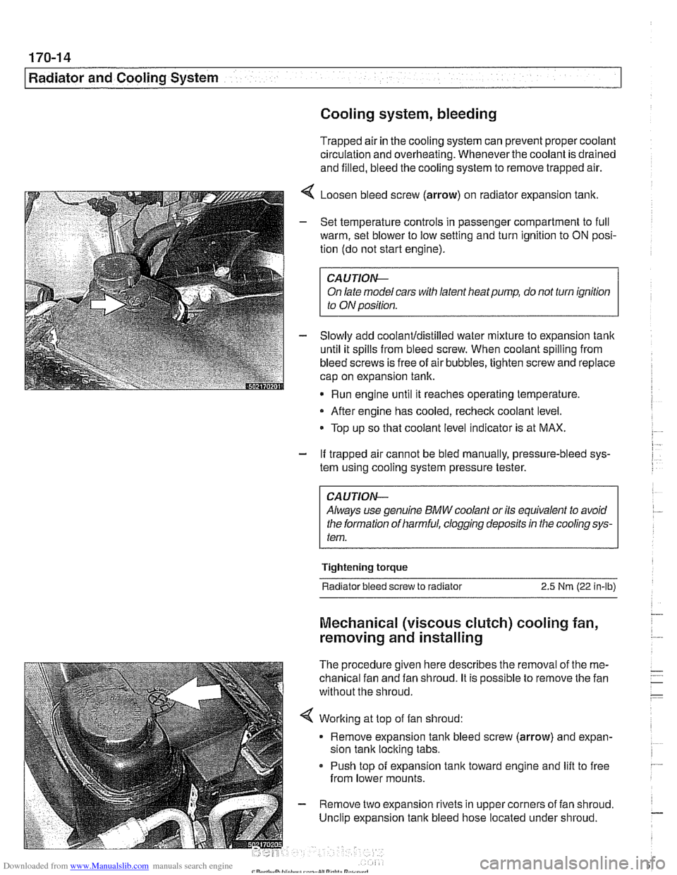
4 Loosen bleed screw (arrow) on radiator expansion tank.
- Set temperature controls in passenger compartment to full
warm, set blower to low setting and turn ignition to
ON posi-
tion (do not start engine).
CAUTIOIG
On late model cars with latent heat pump, do not turn ignition
to ON position.
- Slowly add coolanUdistilled water mixture to expansion tank
until it spills from bleed screw. When coolant spilling from
bleed screws is free of air bubbles, tighten screw and replace
cap on expansion tank.
Run engine until it reaches operating temperature,
- After engine has cooled, recheck coolant level.
Top up so that coolant level indicator is at MAX.
- If trapped air cannot be bled manually, pressure-bleed sys-
tem using cooling system pressure tester.
CA UTlON--
Always use genuine BMW coolant or its equivalent to avoid
the formation of harmful, clogging deposits
in the cooling sys-
tem.
Tightening torque
Radiator bleed screw to radiator 2.5 Nm (22 in-lb)
Mechanical (viscous clutch) cooling fan,
removing and installing
The procedure given here describes the removal of the me-
chanical fan and fan shroud. It is possible to remove the fan
without the shroud.
< Working at top of fan shroud:
Remove expansion tank bleed screw (arrow) and expan-
sion tank locking tabs.
Push top of expansion
tank toward engine and lift to free
from lower mounts.
- Remove two expansion rivets in upper corners of fan shroud.
Unclip expansion tank bleed hose located under shroud.
Page 516 of 1002
Downloaded from www.Manualslib.com manuals search engine
.," --
Radiator and Cooling System --- 1
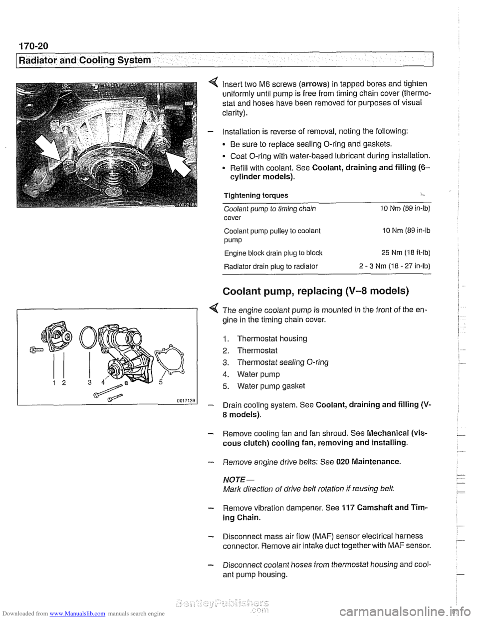
insert two M6 screws (arrows) in tapped bores and tighten
uniformly until pump is free from timing chain cover (thermo-
stat and hoses have been removed for purposes of visual
clarity).
Installation is reverse of removal, noting the following:
Be sure to replace sealing O-ring and gaskets.
Coat O-ring with water-based lubricant during installation.
Refill with coolant. See Coolant, draining and filling
(6-
cylinder models).
Tightening torques
-
Coolant pump to timing chain 10 Nm (89 in-lb)
cover
Coolant pump pulley to coolant
10 Nm (89 in-lb
pump
Engine block drain plug to block 25 Nm (1 8 It-lb)
Radiator drain plug to radiator 2 - 3 Nm (I8 - 27 in-lb)
Coolant pump, replacing (V-8 models)
I 1 < The engine coolant pump is mounted in the front of the en-
gine in ;he timing chain cover.
1. Thermostat housing
2. Thermostat
3. Thermostat sealing O-ring
4. Water pump
5. Water pump gasket
- Drain cooling system. See Coolant, draining and filling (V-
8 models).
- Remove cooling fan and fan shroud. See Mechanical (vis-
cous clutch) cooling fan, removing and installing.
- Remove engine drive belts: See 020 Maintenance.
NOTE-
Mark direction of drive belt rotation if reusing belt,
- Remove vibration dampener. See 117 Camshaft and Tim-
ing Chain.
- Disconnect mass air flow (MAF) sensor electrical harness
connector. Remove air intake duct together with
MAF sensor.
- Disconnect coolant hoses from thermostat housing and cool-
ant pump housing.
Page 530 of 1002
Downloaded from www.Manualslib.com manuals search engine
- Removing left side exhaust manifolds (cylinder bank 5-8):
- Remove heat baffle plate on left side.
Remove oxygen sensor using
BMW special tool 11 7 030
or similar oxygen sensor socket.
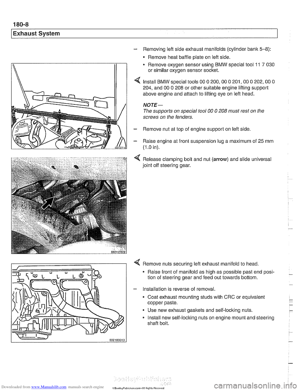
Install
BMW special tools 00 0 200,OO 0 201,OO 0 202,OO 0
204, and 00 0 208 or other suitable engine lifting support
above engine and attach to lifting eye on left head.
NOTE-
The supports on special tool 00 0 208 must rest on the
screws on the fenders.
- Remove nut at top of engine support on left side
- Raise engine at front suspension lug a maximum of 25 mm
(I
.O in).
Release clamping bolt and nut
(arrow) and slide universal
joint off steering gear.
4 Remove nuts securing left exhaust manifold to head,
Raise front of manifold as high as possible past end posi-
tion of steering gear and feed out towards bottom.
- Installation is reverse of removal.
Coat exhaust mounting studs with CRC or equivalent
copper paste.
Use new exhaust gaskets and self-locking nuts.
Install new self-locking nuts on engine mount and steering
shaft bolt.
Page 561 of 1002
Downloaded from www.Manualslib.com manuals search engine
Clutch
Clutch, installing (used SAC components)
When reinstalling a previously used self-adjusting clutch
(SAC), special tools are needed to reset the self-adjusting
ring to its original position.
CAUTIOI\C
Avoidcontaminating clutch friction suifaces with oilorgrease.
Do not touch these
suifaces.
- Place SAC pressure plate on clean worlc suriace.
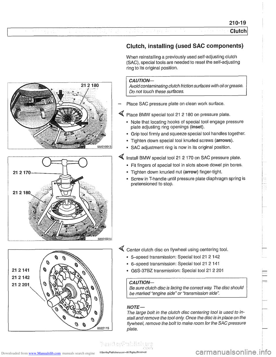
4 Place BMW special tool 21 2 180 on pressure plate
Note that locating hoolts of special tool engage pressure
plate adjusting ring openings
(inset).
Grip tool firmly and squeeze special tool handles together.
Tighten down special tool knurled screws (arrows).
- SAC adjustment ring is now in its original position.
4 Install BMW special tool 21 2 170 on SAC pressure plate.
Fit fingers of special tool in slots above dowel pin bores.
Tighten down knurled nut (arrow) finger-tight.
Screw in T-handle until pressure plate diaphragm spring is
pretensioned to stop.
< Center clutch disc on flywheel using centering tool.
5-speed transmission: Special tool 21 2 142
6-speed transmission: Special tool 21 2 141
G6S-3762 transmission: Special tool 21 2 201
CAUTION--
Be sure clutch disc is lacing the correct way The disc should
be
marked 'kngine side" or 'Transmission side':
NOTE-
The large bolt in the clutch disc centering tool is used to in-
stalland remove the tool only Once the disc is in place on tlie
flywheel, remove the bolt to male room for the SACpressure
plate.
Page 600 of 1002
Downloaded from www.Manualslib.com manuals search engine
250-2
I Gearshift Linkage
This repair group covers transmission gearshift and linkage service for both manual and automatic transmission
equipped vehicles.
To gain access to the complete gearshift mechanism it is
necessary to remove the exhaust system and the driveshaft
as described in
180 Exhaust System and 260 Driveshaft.
NOTE-
In models with automatic transmission, the electronic immo-
bilizer
(EWS) prevents starter operation unless the gear po-
sition is Park or Neutral.
Special tools
BMW suggests the use of one special tool in the removal
of the gear shift lever for manual transmission equipped
I I vehicles.
Manual transmission
gearshift linkage
--
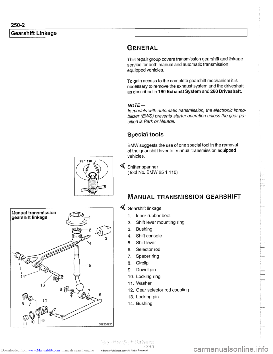
4 Gearshift linkage
1. Inner rubber boot
2. Shift lever mounting ring
3. Bushing
4. Shift console
5. Shift lever
6. Selector rod
7. Spacer ring
8. Circlip
9. Dowel pin
10. Locking ring
11. Washer
12. Gear selector rod coupling
13. Locking pin
14. Bushing
4 Sh~fter spanner
(Tool No. BMW
25 1 11 0)
MANUAL TRANSMISSION GEARSHIFT
Page 659 of 1002
Downloaded from www.Manualslib.com manuals search engine
1 320 Steering and Wheel Alignment
General ........................... .32 0.2
Special tools
........................ .32 0.2
Steering system
..................... .32 0.4
Steering system variations
............. .32 0.5
Steering system warnings and cautions
... .32 0.6
Steering Wheel .................... .32 0.7
Steering wheel. removal and installation
.. .32 0.7
Steering Column ................. .32 0.1 0
Steering column components .......... .32 0.10
Steering column trim, removing
and replacing
...................... .32 0.10
lgnition switch ring antenna (EWS).
removing and installing
............... .32 0.1 1
lgnition lock cylinder.
removing and installing
............... .32 0-1 1
Steering column lock. removing
and installing
....................... .32 0.12
lgnition
interloclc cable. removing and installing
(models with automatic transmission)
... .32 0.13
Interlock cable. adjusting
(models with automatic transmission)
... .32 0.14
Steering column. removing and installing
. .32 0.14
Steering column adjustment motors.
removing and installing
............... .32 0.16
Power Steering Pump ............. .32 0.17
Power steering pump. removing
and installing
....................... .32 0.1 7
Power steering system.
bleeding and filling
.................. .32 0.18
Rack and Pinion Steering
(6-cylinder models)
............... 320-19
Rack and pinion steering components
(6-cylinder models)
.................. 320-1 9
Steering rack. removing and installing
.... 320-19
Steering
rack boot. replacing ........... 320-22
Tie rod (outer). replacing
.............. 320-22
Tie rod (inner). replacing
.............. 320-23
Steering Gearbox (V-8 models) .... 320-24
Steering gearbox system components
. .
(V-8 models) ....................... 320-24
Steering gearbox, removing and installing 320-25
Pitman arm. removing and installing ..... 320-28
Pitman arm. adjusting ................ 320-29
Steering idler arm. removing
and installing
....................... 320-30
Idler arm bushing. replacing ........... 320-31
Center tie rod. replacing
.............. 320-32
Wheel Alignment .................. 320-33
Camber
........................... 320-33
Caster
............................ 320-33
Front toe and toe difference angle
....... 320-34
Reartoe ........................... 320-34
Preparing for alignment
............... 320-35
Alignment specifications tables
......... 320-35
Page 669 of 1002
Downloaded from www.Manualslib.com manuals search engine
Steering and Wheel ~li~nrnentl
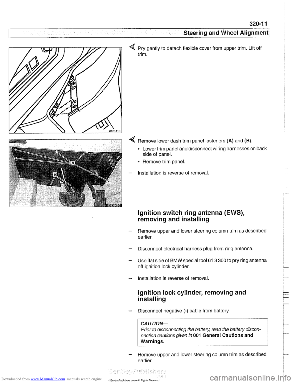
q Pry gently to detach flexible cover from upper trim. Lift off
trim.
< Remove lower dash trim panel fasteners (A) and (B).
Lower trim panel and disconnect wiring harnesses on back
side of panel.
Remove trim panel.
- Installation is reverse of removal.
Ignition switch ring antenna (EWS),
removing and installing
- Remove upper and lower steering column trim as described
earlier.
- Disconnect electrical harness plug from ring antenna.
- Use flat side of BMW special tool 61 3 300 to pry ring antenna
off ignition lock cylinder.
- Installation is reverse of removal.
lgnition lock cylinder, removing and
installing
- Disconnect negative (-) cable from battery.
CAUTION-
Prior to disconnecting the battery, read the battery discon-
nection cautions given
in 001 General Cautions and
Warnings.
- Remove upper and lower steering column trim as described
earlier.
Page 772 of 1002
Downloaded from www.Manualslib.com manuals search engine
Brakes
- Open bleeder screw. Carry out bleeding procedure with
BMW Service Tester until clear, bubble-free fluid flows.
Models with DSC: After BMW Service Tester bleeding rou-
tine has finished, press brake pedal to floor
5 times until
clear, bubble-free fluid runs out. Close right rear bleeder
valve.
Models with ASC: Close right rear bleeder valve.
- Repeat procedure at left rear brakes.
- Repeat BMW Service Tester bleeding at right front brakes.
Models with DSC: After
BMW Service Tester bleeding rou-
tine has finished, press brake pedal to floor
5 times until
clear, bubble-free fluid runs out. Close right front bleeder
valve.
Models with ASC: After BMW Service Tester bleeding rou-
tine has finished, press brake pedal to floor
12 times until
clear, bubble-free fluid runs out. Close right front bleeder
valve.
- Repeat procedure at left front brakes.
- Remove brake bleeding apparatus and disconnect BMW
Service Tester. Top up brake fluid. Check to make sure
brake 1
fluid reservoir cap seal is intact.
Tightening torques Bleeder screws (wrench size)
- 7 rnrn screw
3.5 - 5 Nrn (2.5 - 3.7 ft-lb)
11 rnrn screw 12-16Nrn(9-12ft-lb)
Page 789 of 1002
Downloaded from www.Manualslib.com manuals search engine
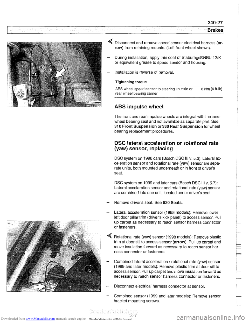
4 Disconnect and remove speed sensor electrical harness (ar-
row) from retaining mounts. (Lefl front wheel shown).
- During installation, apply thin coat of StaburagsBNBU 12/K
or equivalent grease to speed sensor and housing.
- Installation is reverse of removal.
Tightening torque
ABS wheel speed sensor to steering knuckle or 8 Nm (6 It-lb)
rear wheel bearing carrier
ABS impulse wheel
The front and rear impulse wheels are integral with the inner
wheel bearing seal and not available as separate part. See
310 Front Suspension or 330 Rear Suspension for wheel
bearing replacement procedures.
DSC lateral acceleration or rotational rate
(yaw) sensor, replacing
DSC system on 1998 cars (Bosch DSC Ill v. 5.3): Lateral ac-
celeration sensor and rotational rate (yaw) sensor are sepa-
rate units, both mounted underneath or in front of driver's
seat.
DSC system on 1999 and later cars (Bosch DSC
Ill v. 5.7):
Lateral acceleration sensor and rotational rate (yaw) sensor
are combined into one unit, located under driver's seat.
- Remove driver's seat. See 520 Seats.
- Lateral acceleration sensor (1 998 models): Remove lower
lefl door pillar trim (driver's
kick panel) to access sensor. Pull
up carpet as necessary to reach sensor harness connector
or fasteners.
4 Rotational rate (yaw) sensor (1998 models): Remove plastic
trim at door sill to access sensor (arrow). Pull up carpet and
move insulation forward as necessary to reach sensor har-
ness connector or fasteners.
- Combined lateral acceleration / rotational rate (yaw) sensor
(1 999 and later models): Remove plastic trim at door sill to
access sensor. Pull up carpet and move insulation forward as
necessary to reach sensor harness connector or fasteners.
- Disconnect electrical harness connector at sensor.
- Combined sensor (1 999 and later models): Remove sensor
bracket mounting screws.
Page 790 of 1002
Downloaded from www.Manualslib.com manuals search engine
340-28
Brakes
- Remove sensor mounting screws. Lift sensor away from
bracket.
- Installation is reverse of removal.
CAUTION-
Be sure to tighten the DSC acceleration sensor(s) and
mounting bracket, if applicable, to specified torques. The
sensor
is vibration sensitive and subject to cause DSC
malfunctions if installed improperly.
a After replacing the sensor, perform sensor adjustment
using either DIS or
MoDiC under Service Functions
menu.
Tightening
torques
Lateral acceleration I rotational rate sensor 8 Nm (6 R-ib)
to bracket
Sensor bracket to body
8 Nm (6 ft-lb)
DSC steering angle sensor, removing and
installing
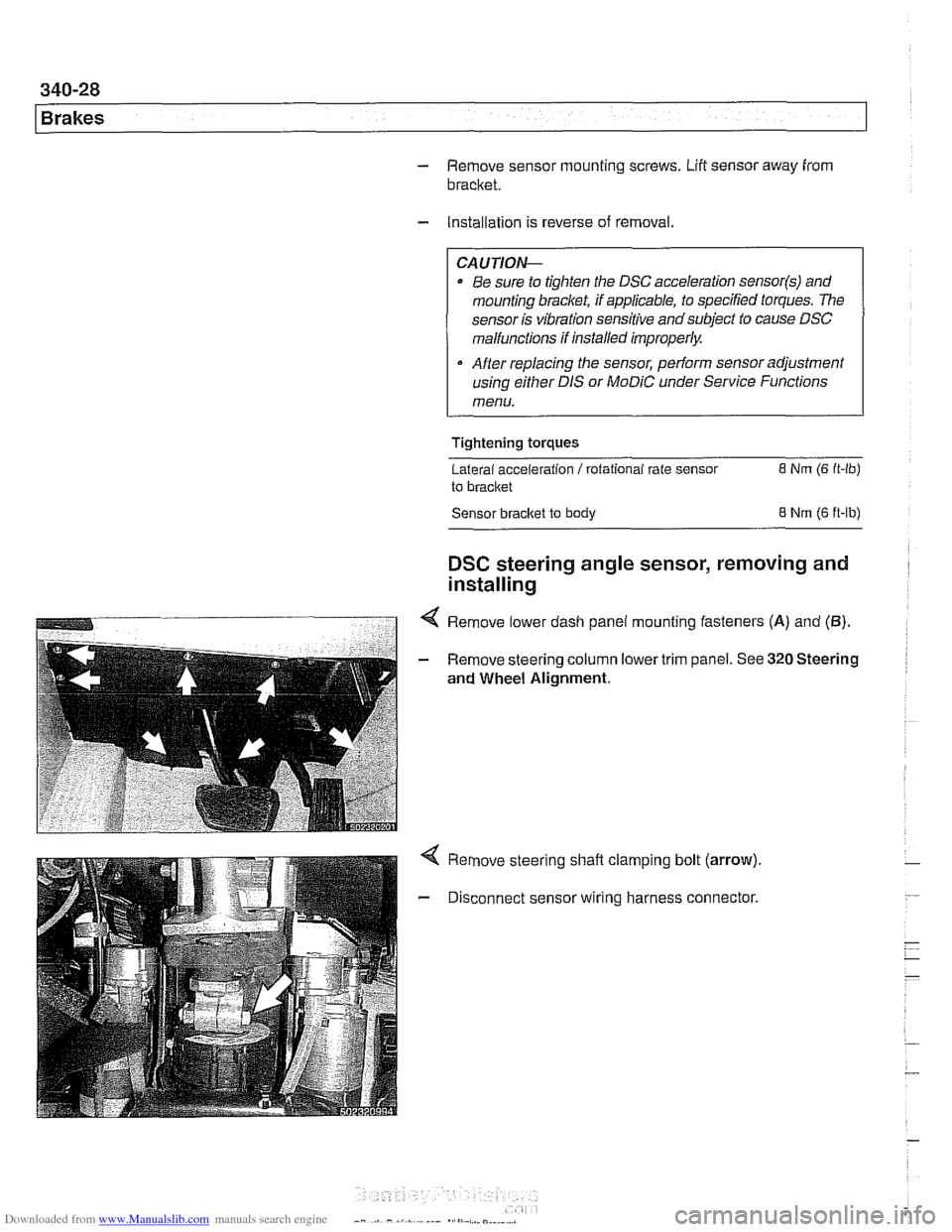
4 Remove lower dash panel mounting fasteners (A) and (5).
- Remove steering column lower trim panel. See 320 Steering
and Wheel Alignment.
Remove steering shaft clamping bolt (arrow).
Disconnect sensor wiring harness connector.