Engine compartment BMW 528i 1998 E39 Owner's Manual
[x] Cancel search | Manufacturer: BMW, Model Year: 1998, Model line: 528i, Model: BMW 528i 1998 E39Pages: 1002
Page 273 of 1002
Downloaded from www.Manualslib.com manuals search engine
Camshaft Timing Chain
VANOS control unit, removing
(M52 TU and M54 engines)
This procedure includes removal of the Double VANOS con-
trol unit.
NOTE-
If the Double VANOS control unit is being replaced, camshaft
timing must be checked. This procedure requires multiple
special tools. Be sure to read the procedures through before
beginning the repair.
- Working inside luggage compartment, disconnect negative
(-) battery cable.
Prior to disconnecting the
batteg read the battery discon-
nection cautions given in
001 General Cautions and
Remove engine cooling fan assembly. See 170 Radiator
and Cooling System.
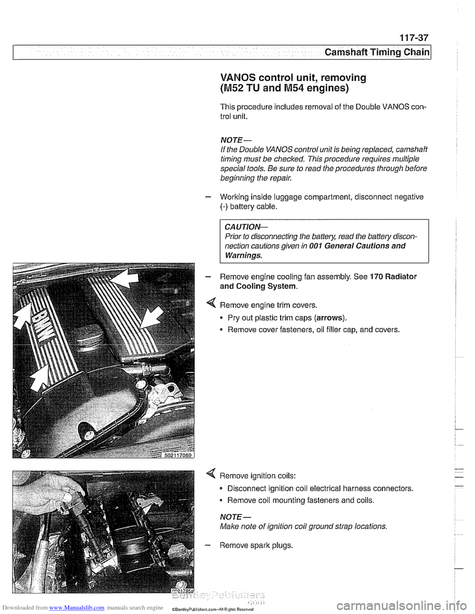
Remove engine trim covers.
Pry out plastic trim caps (arrows).
Remove cover fasteners, oil filler cap, and covers.
Remove ignition coils:
Disconnect ignition coil electrical harness connectors.
Remove coil mounting fasteners and coils.
NOTE-
Make note of ignition coil ground strap locations.
Remove spark plugs,
Page 315 of 1002
Downloaded from www.Manualslib.com manuals search engine
Camshaft Timing chain/
Camshaft timing, checking and adjusting
(M62 engine)
WARNING -
Allow engine to cool before beginning this procedure. 1
- Working inside luggage compartment, disconnect negative
battery cable.
CAUTIOI\C
Prior to disconnecting battery cable, read the battery discon-
nection cautions given
in 001 General Cautions and
Warninss.
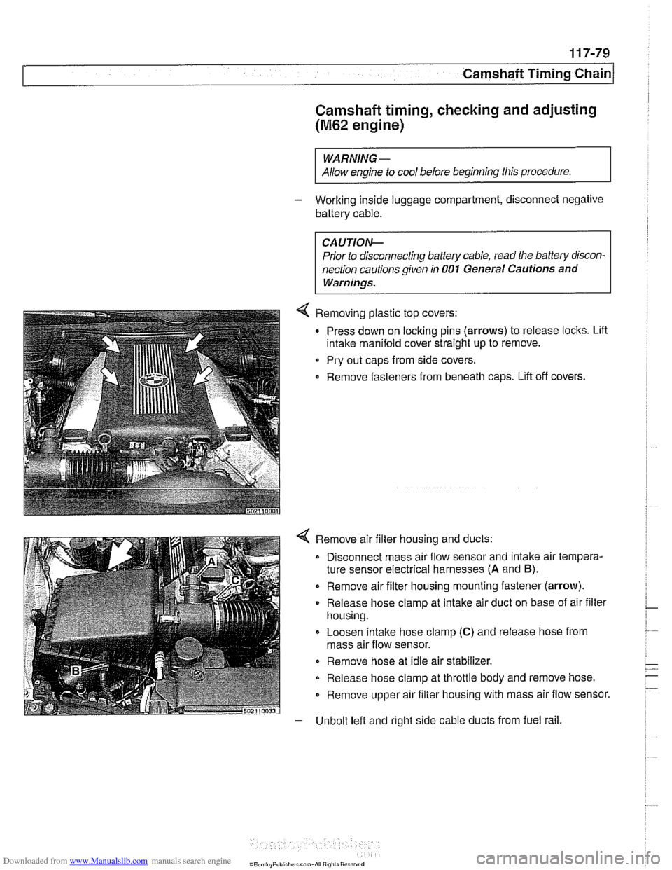
4 Removing plastic top covers:
Press down on locking pins (arrows) to release locks. Lift
intake manifold cover straight up to remove.
Pry out caps from side covers.
Remove fasteners from beneath
caDs. Lift off covers.
4 Remove air filter housing and ducts:
Disconnect mass air flow sensor and intake air tempera-
ture sensor electrical harnesses
(A and B).
Remove air filter housing mounting fastener (arrow).
Release hose clamp at intake air duct on base of air filter
housing.
Loosen intake hose clamp
(C) and release hose from
mass air flow sensor.
Remove hose at idle air stabilizer.
Release hose clamp at throttle body and remove hose.
Remove upper air filter housing with mass air flow sensor.
- Unbolt left and right side cable ducts from fuel rail.
Page 324 of 1002
Downloaded from www.Manualslib.com manuals search engine
-
I Lubrication System - I
Oil pressure, checking
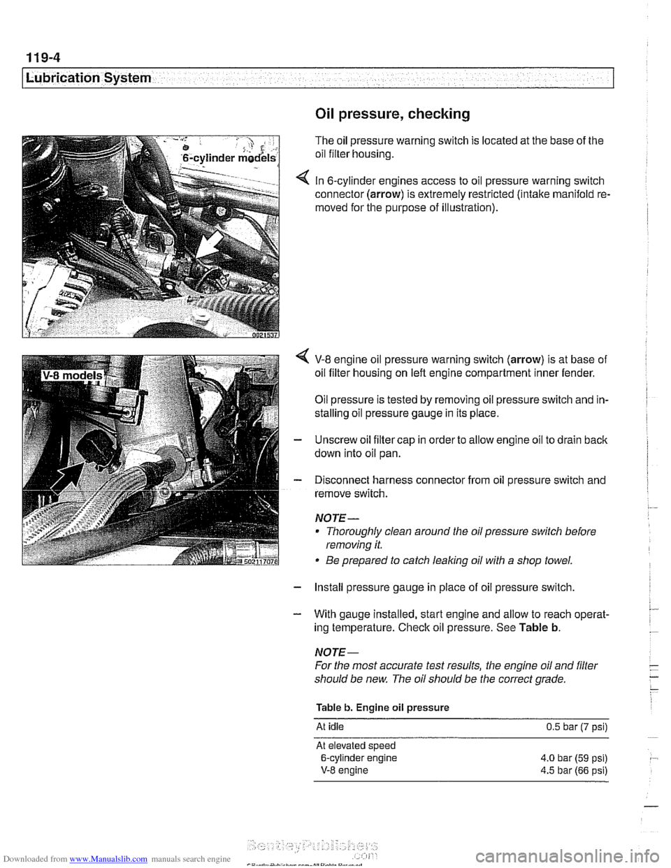
The oil pressure warning switch is located at the base of the
oil filter housing.
In 6-cylinder engines access to oil pressure warning switch
connector (arrow) is extremely restricted (intake manifold re.
moved for the purpose of illustration).
V-8 engine oil pressure warning switch (arrow) is at base of
oil filter housing on left engine compartment inner fender.
Oil pressure is tested by removing oil pressure switch and in-
stalling oil pressure gauge in its place.
Unscrew oil filter cap in order to allow engine oil to drain back
down into oil pan.
Disconnect harness connector from oil pressure switch and
remove switch.
NOJE-
Thoroughly clean around the oil pressure switch before
removing it.
Be prepared to catch leaking oil with a shop towel.
- Install pressure gauge in place of oil pressure switch,
- With gauge installed, start engine and allow to reach operat-
ing temperature. Check oil pressure. See Table b.
NOJE-
For the most accurate test results, the engine oil and filter
should be new. The oil should be the correct grade.
Table b. Engine oil pressure
At idle 0.5 bar (7 psi)
At elevated speed
6-cylinder engine 4.0 bar
(59 psi)
V-8 engine 4.5 bar (66 psi)
Page 358 of 1002
Downloaded from www.Manualslib.com manuals search engine
.-
ignition System
Disabling ignition system
The ignition system operates in a lethal voltage range and
should be disabled any time engine service or repair work is
being done that requires the ignition to be switched on.
The engine management system can be disabled by remov-
ing the DME main relay. The relay is located in the electronics
box (E-box) in the left rear of the engine
compartment, be.
neath the interior microfilter housing.
CAUTION- Relay locations may
vary. Use care when identifying relays.
See
610 Electrical Component Locations.
Checking for spark
CAUTION-
If
a spark test is done incorrecth damage to the Engine Con-
trol Module
(ECM) or the ignition coils may result.
NOTE-
Spark plug replacement is covered in 020 Maintenance.
Check~ng for spark is d~fflcult on englnes wlth d~str~butorless
ignition systems.
Try removing the spark plugs and inspecting for differences between them.
A poor-firing plug may be wet with fuel and/or ~. - ~
black and sooty, but not always. If a coil is not operating, the
engine management system will electrically disable the fuel
injector to that cylinder. The key is to look for differences be-
tween cylinders.
Ignition coil assembly, testing and
replacing
C4 UTION-
Use a digital multimeter for the following tests. I
- Remove plastic engine cover from top of valve cover by pry-
ing off bolt covers and removing cover mounting bolts.
- Raise car slowly while constantly checking position of jack
and car.
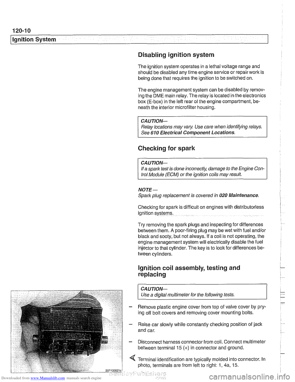
- Disconnect harness connector from coil. Connect multimeter
between terminal 15
(+) in connector and ground.
4 Terminal identification are typically molded into connector. In
photo, terminals are from left to right: 1,
4a, 15.
Page 369 of 1002
Downloaded from www.Manualslib.com manuals search engine
Battery, Starter, ~lternatorl
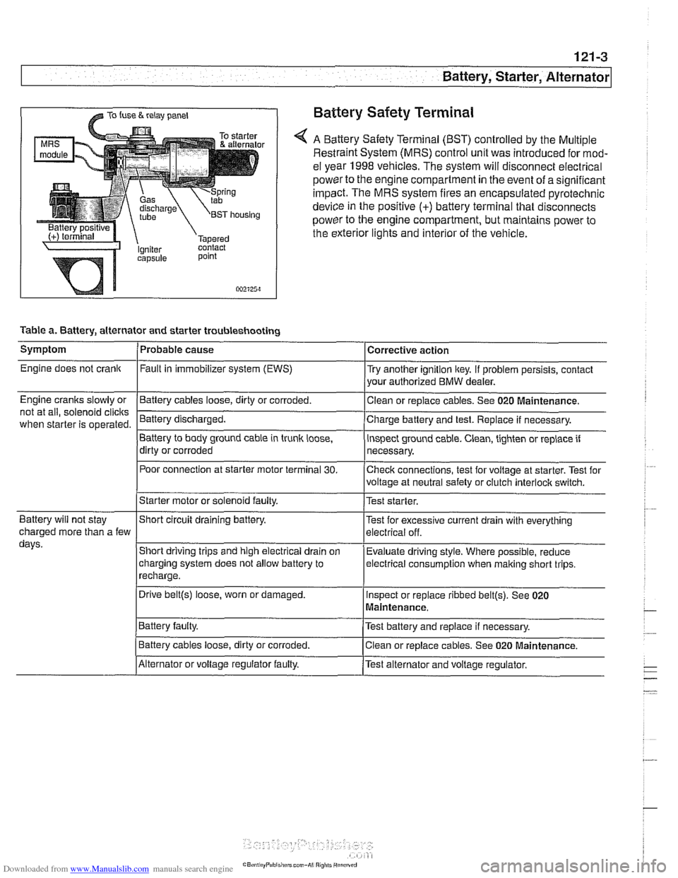
@ TO fuse & relay panel Battery Safety Terminal
A Battery Safety Terminal (BST) controlled by the Multiple
Restraint System (MRS) control unit was introduced for mod-
el year 1998
vehicles. The system will disconnect electrical
power to the engine compartment
in the event of a significant
impact. The MRS system fires an encapsulated pyrotechnic
device
in the positive (+) battery terminal that disconnects
power to the engine compartment, but maintains power to
the exterior lights and interior of the vehicle.
point
002125~1
Table a. Battery, alternator and starter troubleshooting
1-
/Starter motor or solenoid faulty. l~est starter.
Symptom
Engine does not crank
Engine cranks slowly or
not at all, solenoid
clicits
when starter is operated.
I I
Battery will not stay IShort circuit draining battery. l~est for excessive current drain with everything
Probable cause
Fault
in immobilizer system (EWS)
-Clean Battery cables loose, dirty or corroded.
Battery discharged.
Battery to body ground cable in trunk
loose,
dirty or corroded
Poor connection at starter motor terminal
30.
Corrective action
Try another ignition key. If problem persists, contact
your authorized BMW dealer.
or replace cables. See 020
~aintenance.
Charge battery and test. Replace if necessary.
inspect ground cable. Clean, tighten or replace if
necessary.
Checlc connections, test for voltage at starter. Test for
voltage at neutral safety or clutch
interloclc switch.
charged more than a few
days.
I~atter~ faulty. /Test battery and replace if necessary.
Short driving trips and high electrical drain
on
charging system does not allow battery to
recharge.
. I
I Battery cables loose, dirty or corroded. Iclean or replace cables. See 020 Maintenance.
Evaluate driving
style. Where possible, reduce
electrical
consumption when malting short trips.
Drive
belt@) loose, worn or damaged.
IAlternator or voltage regulator faulty. /Test alternator and voltage regulator.
Inspect
or replace ribbed
belt@). See 020
Maintenance.
Page 372 of 1002
Downloaded from www.Manualslib.com manuals search engine
.
Battery, Starter, Alternator
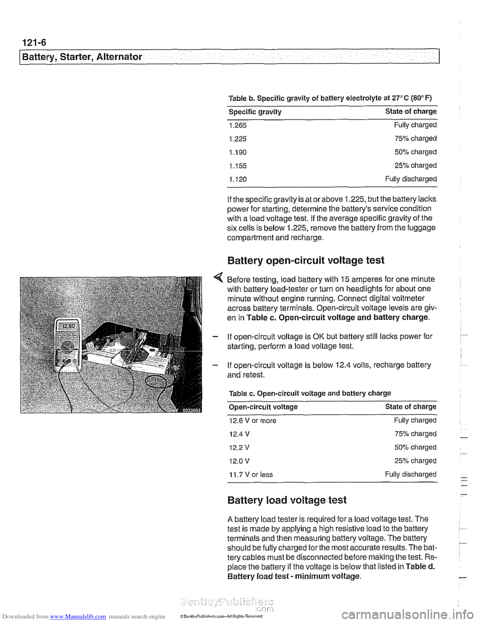
Table b. Specific gravity of battery electrolyte at 27°C (80°F)
Specific gravity State of charge
1.265 Fully charged
1.225 75% charged
1.190 50% charged
1.155 25% charged
1.120 Fully discharged
if the specific gravity is at
orabove 1.225, butthe battery lacks
Dower for
startinq, determine the battew's service condition
with a load volta& test. if the average specific gravity of the
six cells is below 1.225, remove the battery from the luggage
compartment and recharge.
Battery open-circuit voltage test
Before testing, load battery with 15 amperes for one minute
with battery load-tester or turn on headlights for about one
minute without engine running. Connect digital voltmeter
across battery terminals. Open-circuit voltage levels are giv-
en in Table
c. Open-circuit voltage and battery charge.
If open-circuit voltage is
OK but battery still lacks power for
starting, perform a load voltage test.
If open-circuit voltage is
below 12.4 volts, recharge battery
and retest.
Table c. Open-circuit voltage and battery charge
Open-circuit voltage State of charge
12.6 V or more
12.4 V
12.2v
12.0 v
Fully charged
75% charged
50% charged
25% charged
11.7Vorless Fully discharged
Battery load voltage test
A battery load tester is required for a load voltage test. The
test is made by applying a high resistive load to the battery
terminals and then measuring battery voltage. The battery
should be
fully charged forthe most accurate results. The bat-
tery cables must be disconnected before
malting the test. Re-
place the battery if the voltage is below that listed in Table d.
Battery load test
- minimum voltage.
Page 373 of 1002
Downloaded from www.Manualslib.com manuals search engine
Battery, Starter, ~lternatorl
WARNING-
Always wear protective goggles and clothing when perform-
ing a load test.
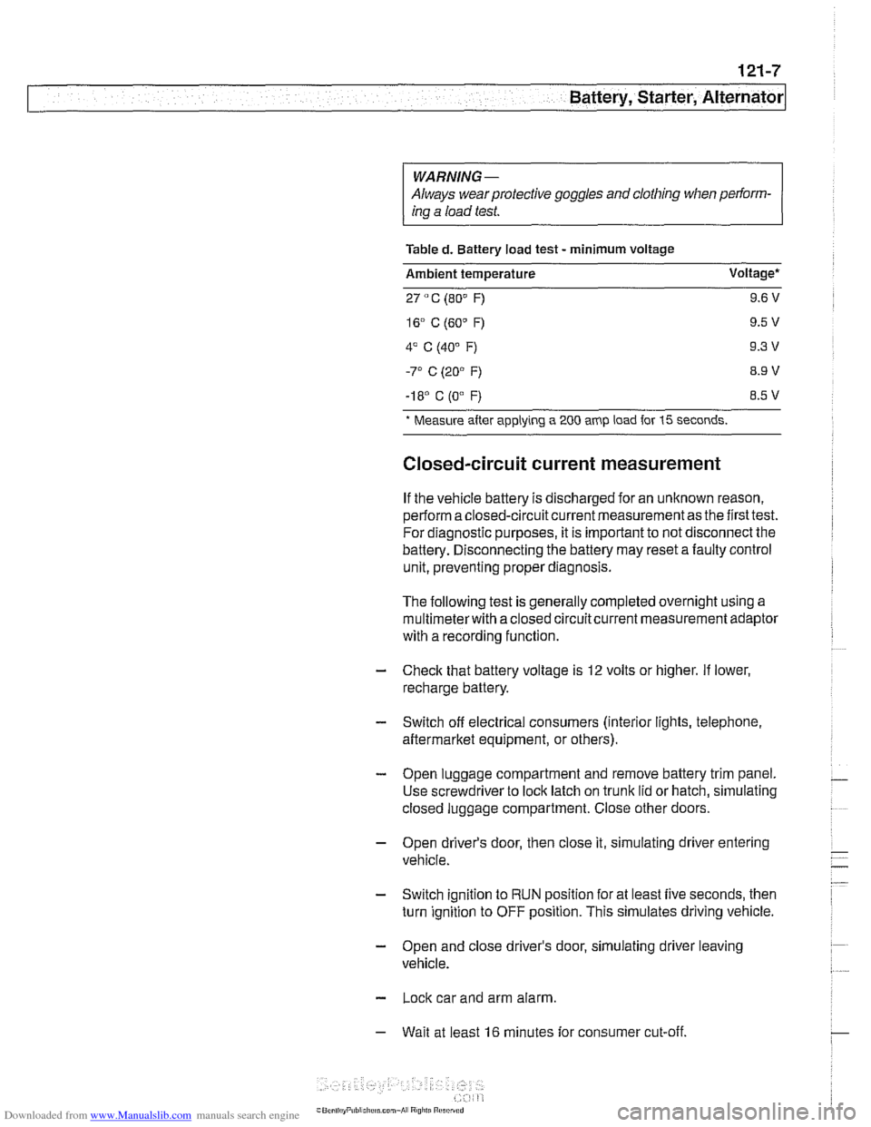
Table
d. Battery load test - minimum voltage
Ambient temperature Voltage*
27
" C (80" F) 9.6 V
-I 8' C (0"
F) 8.5 V
* Measure
after applying a 200 amp load for 15 seconds.
Closed-circuit current measurement
If the vehicle battery is discharged for an unknown reason,
perform a closed-circuit current measurement as the first test.
For diagnostic purposes, it is important to not disconnect the
battery. Disconnecting the battery may reset a faulty control
unit, preventing proper diagnosis.
The following test is generally completed overnight using a
multimeterwith a closed circuitcurrent measurement adaptor
with a recording function
- Check that battery voltage is 12 volts or higher. If lower,
recharge battery.
- Switch off electrical consumers (interior lights, telephone,
aftermarket equipment, or others).
- Open luggage compartment and remove battery trim panel.
Use screwdriver to lock latch on trunk lid or hatch, simulating
closed luggage compartment. Close other doors.
- Open driver's door, then close it, simulating driver entering
vehicle.
- Switch ignition to RUN position for at least five seconds, then
turn ignition to OFF position. This simulates driving vehicle.
- Open and close driver's door, simulating driver leaving
vehicle.
- Lock car and arm alarm.
- Wait at least 16 minutes for consumer cut-off.
Page 375 of 1002
Downloaded from www.Manualslib.com manuals search engine
121-9
Battery, Starter, ~lternatorl
Battery charging
Discharged batteries can be recharged using a batterycharg-
er. Remove the battery from the trunk during charging.
Prolonged charging causes electrolyte evaporation to a level
that can damage the battery. It is best to use a low-current
charger
(6 amperes or less) to prevent battery damage
caused by overheating.
WARNING -
Hydrogen gas given off by the battery during charging is ex-
plosive. Do not smoke.
Keep open flames away from the top
ofthe batte~ and prevent electrical sparks by turning off the
battery charger before connecting or disconnecting it.
Battery electrolyte (sulfuric acid) can damage the car. If
electrolyte is spilled, clean the area with a solution
ofbak-
ing soda and water.
Always allow a frozen battery to thaw before attempting
to recharge it.
Always disconnect both battery cables and remove bat-
tery from vehicle during battery charging. Do not ex-
ceed
16.5 charging voltage at the battery
Battery safety terminal, replacing
If the battery safety terminal has been triggered, investigate
and correct the cause prior to replacement.
- Working in right side of luggage compartment, remove bat-
tery trim panel.
- Disconnect negative (-) battery terminal and cover with
insulator.
- Disconnect positive (+) cable from battery.
- Release positive (+) cable from cable brackets on luggage
compartment wall. Lay new repair cable parallel to positive
cable.
- Mark off length of new cable on old cable. Allow 10 cm
(2.5 in) of slack.
- Saw through old cable.
Do not use bolt cutters or similar tools to cut through cable.
A cable end that has been squashed
flat will not fit into the
Page 384 of 1002
Downloaded from www.Manualslib.com manuals search engine
121-18
I Battery, Starter, Alternator
Alternator, removing and installing
(M62 TU engine, water cooled)
V-8 models produced after 9/98 are equipped with a water
cooled alternator.
CAUTION-
Allow engine to cool before removing alternator as coolant
will
escape from the alternator water jacket.
- Disconnect negative (-) battery cable
CAUTION- Prior to disconnecting the
battew read the battery discon-
nection cautions given in
001 General Warnings and Cau-
tions.
- Remove radiator cooling fan and fan shroud. See 170 Radi-
ator and Cooling System.
- Drain engine cooling system. See 170 Radiator and Cool-
ing System.
- Remove alternator drive belt. See 020 Maintenance.
- Disconnect battery lead (terminal 30 or B+) and two-pin har-
ness connector from front of alternator.
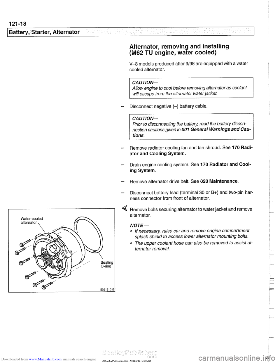
I < Remove bolts securing alternator to water jacket and remove
aling ring
alternator.
NOTE- If necessary, raise car and remove engine compartment
splash shield to access lower alternator mounting bolts.
The upper coolant hose can also
be removed to assist al-
ternator removal.
Page 397 of 1002
Downloaded from www.Manualslib.com manuals search engine
Fuel Injection 1
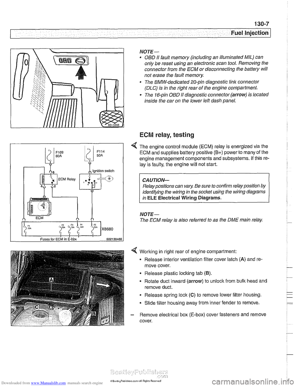
Working in right rear of engine compartment:
Release interior ventilation filter cover latch
(A) and re-
move cover.
Release plastic locking tab
(6).
Rotate duct inward (arrow) to unlock from bulk head and
remove duct.
Release spring
lock (C) to remove lower iilter housing.
Slide filter housing away from inner fender to remove.
- Remove electrical box (E-box) cover fasteners and remove
cover.
NOTE-
OBD I1 fault memory (including an illuminated MIL) can
only be reset using an electronic scan tool. Removing the
connector from the ECM or disconnecting the battery will
not erase the fault
memory.
The BMW-dedicated 20-pin diagnostic linlc connector
(DLC) is in the right rear of the engine compartment.
The 16-pin OBD
I1 diagnostic connector (arrow) is located
inside the car on the lower left dash panel.
ECM relay, testing
Fuses lor ECM In E-bbx 502130488
4 The engine control module (ECM) relay is energized via the
ECM and supplies battery positive
(B+) power to many of the
engine management components and subsystems.
If this re-
lay is faulty, the engine will not start.
Relay positions can vary. Be sure to confirm relay position by
identifying the wiring in the socket using the wiring diagrams
in
ELE Electrical Wiring Diagrams.
NOTE-
The ECM relay is also referred to as the DME main relay.