Engine compartment BMW 528i 1998 E39 Owner's Guide
[x] Cancel search | Manufacturer: BMW, Model Year: 1998, Model line: 528i, Model: BMW 528i 1998 E39Pages: 1002
Page 413 of 1002
Downloaded from www.Manualslib.com manuals search engine
- -.
Fuel Injection
SIEMENS MIS 42.0 AND 43.0
When system faults are detected, a diagnostic trouble code
(DTC) is stored in the engine control module (ECM). The MIL
also illuminates
if an emissions-related fault is detected.
When faults arise, or
if the malfunction indicator lamp (MIL) is
illuminated, begin troubleshooting by connecting BMW ser-
vice tester
DISplus, MoDiC, GTI or equivalent scan tool. The
capabilities of OBD
II software has the potential to save hours
of diagnostic time and to help avoid incorrect component re-
placement and possible damage to system components.
CAUTION-
* The tests in this section may set fault codes (DTCs) in tlie
ECM and illuminate the MIL. After all testing is completed,
access and clear DTC fault
memory using an OBD I/ or
BMW compatible scan tool. See
OBD On-Board Diag-
nostics.
Only use a
dgital multimeter for electrical tests.
Relay positions can vary. Be sure to confirm
relayposi-
tion by identifying the wiring in the socket using the wir-
ing diagrams found in
ELE Electrical Wiring
Diagrams.
NOTE-
- OBD I1 fault memory. (including an illuminated MIL! can
only be reset using the special scan tool. Removing the
connector from the ECM or disconnecting the battery will
not erase the fault memory.
The BMW-dedicated 20-pin diagnostic
linlc connector
(DLC) is in the right rear of the engine compartment The
20-pin DLC is discontinued on models after
6/2000.
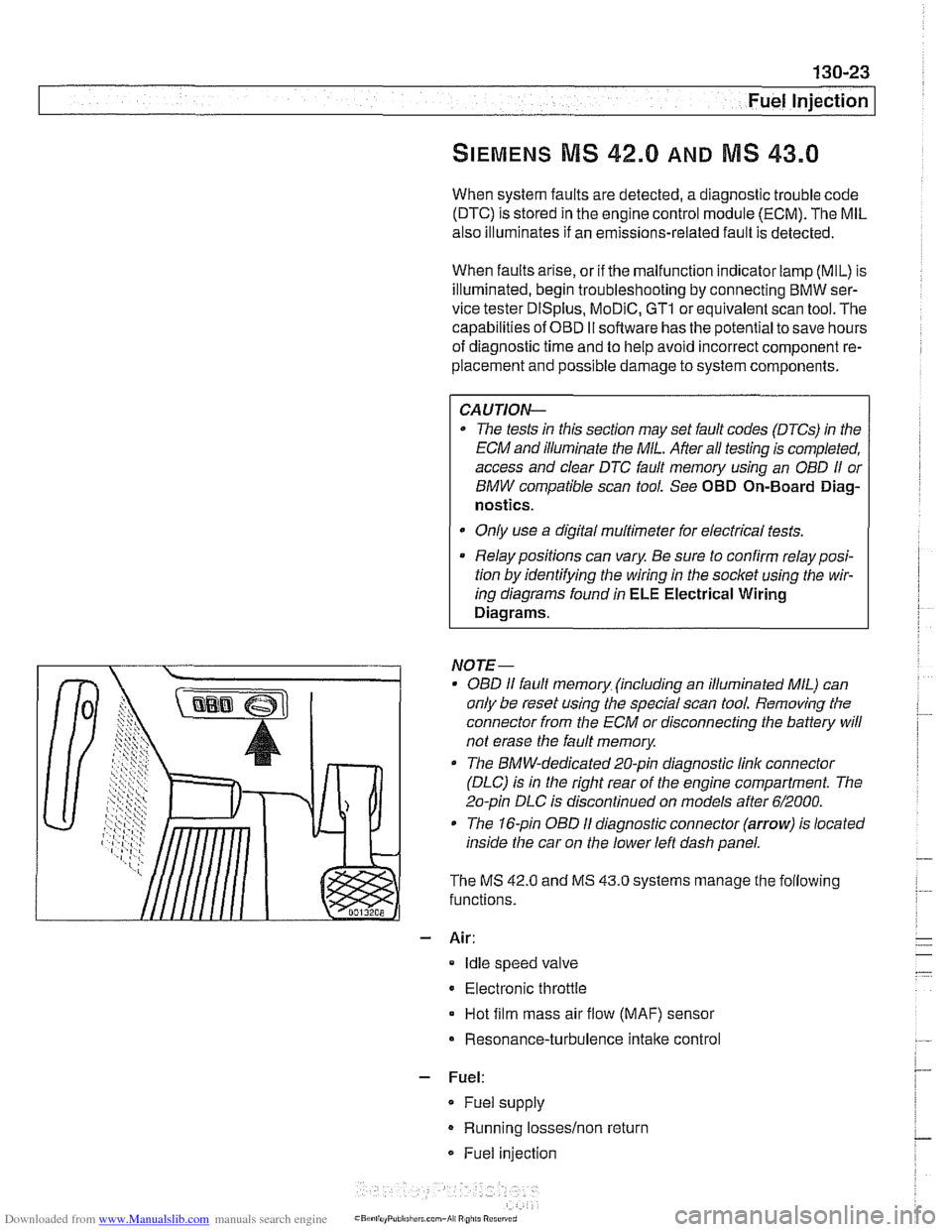
The 1 &pin OBD I1 diagnostic connector (arrow) is located
inside the car on the lower left dash panel.
The MS
42.0 and MS 43.0 systems manage the following
functions.
- Air:
Idle speed valve
Electronic throttle
Hot film mass air flow (MAF) sensor
Resonance-turbulence intake control
- Fuel:
* Fuel supply
Running losseslnon return
Fuel injection
Page 417 of 1002
Downloaded from www.Manualslib.com manuals search engine
-
Fuel Injection
ECM relay, testing
The engine control module (ECM) relay is energized via the
ECM and supplies battery positive
(Bc) power to many of the
engine management components and subsystems. If this re-
lay is faulty, the engine will not start.
NOTE-
The ECM relay is also referred to as the DME main relay
ECM relay powers:
ECM
Ignition coils
* Fuel injection
Evaporative leak detection pump
Idle air actuator
- Camshaft sensors Evaporative emissions valve
Hot film mass air flow sensor
Fuel pump relay
Oxygen sensor heaters
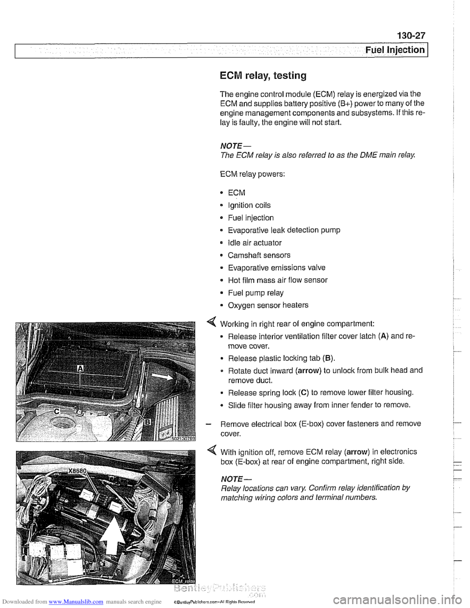
4 Working in right rear of engine compartment:
Release interior ventilation filter cover latch
(A) and re-
move cover.
Release plastic locking tab
(B).
Rotate duct inward (arrow) to unlock from bulk head and
remove duct.
Release spring lock
(C) to remove lower filter housing.
Slide filter housing away from inner fender to remove.
- Remove electrical box (E-box) cover fasteners and remove
cover.
With ignition off, remove ECM relay (arrow) in electronics
box (E-box) at rear of engine compartment, right side.
NOTE-
Relay locations can vary Confirm relay identification by
matching wiring colors and terminal numbers.
Page 423 of 1002
Downloaded from www.Manualslib.com manuals search engine
Fuel lniection I
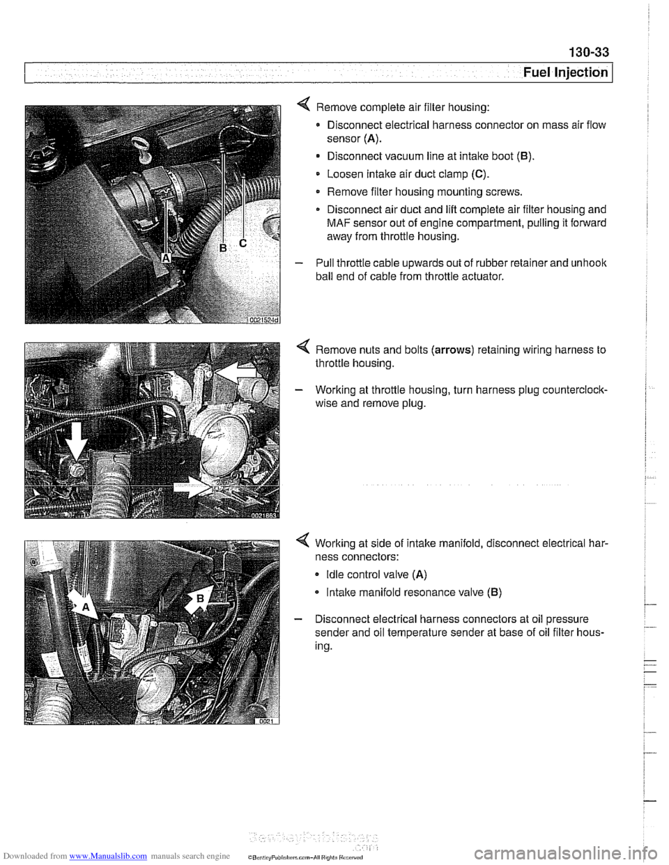
4 Remove complete air filter housing:
Disconnect electrical harness connector on mass air flow
sensor
(A).
Disconnect vacuum line at intake boot (B).
Loosen Intake air duct clamp (C).
Remove filter housing mounting screws
Disconnect air duct and
lift complete air filter housing and
MAF sensor out of engine compartment, pulling it forward
away from throttle housing.
- Pull throttle cable upwards out of rubber retainer and unhoolc
ball end of cable from throttle actuator.
4 Remove nuts and bolts (arrows) retaining wiring harness to
throttle housing.
- Working at throttle housing, turn harness plug counterclock-
wise and remove plug.
4 Working at side of intake manifold, disconnect electrical har-
ness connectors:
Idle control valve (A)
lntalce manifold resonance valve (B)
- Disconnect electrical harness connectors at oil pressure
sender and oil temperature sender at base of oil filter hous-
ing.
CO,l,> ti,, "F"bl,rl,irrm.,-AI ",",>ti
Page 425 of 1002
Downloaded from www.Manualslib.com manuals search engine
Fuel Injection
MS 43.0 throttle valve assembly, replacing
The electronic throttle valve assembly forthe MS43.0 system
is referred to as
EDK (electronic throttle valve). There is no
mechanical (cable) link between the accelerator pedal and
the throttle plate.
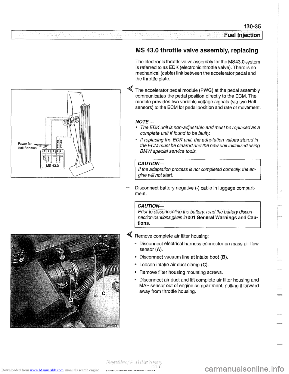
< The accelerator pedal module (PWG) at the pedal assembly
communicates the pedal position directly to the ECM. The
module provides two variable voltage signals (via two Hail
sensors) to the ECM for pedal position and rate of movement.
NOTE-
The EDK unit is non-adjustable and must be replaced as a
complete unit if found to be faulty
If replacing the
EDK unit, the adaptation values stored in
the
ECM must be cleared and the new unit initialized using
BMW special service tools.
CAUTIOIG
If the adaptation process is not completed correctk the en-
qine will not start
- Disconnect battery negative (-) cable in luggage compart-
ment.
CAUTION-
Prior to disconnecting the battery, read the battery discon-
nection cautions given in
001 General Warnings and Cau-
tions.
< Remove complete air filter housing:
- Disconnect electrical harness connector on mass air flow
sensor
(A).
Disconnect vacuum line at intake boot (6).
Loosen intaite air duct clamp (C).
Remove filter housing mounting screws.
Disconnect air duct and lift complete air filter housing and
MAF sensor out of engine compartment, pulling it forward
away from throttle housing.
Page 436 of 1002
Downloaded from www.Manualslib.com manuals search engine
130-46
Fuel Injection
When system faults are detected, a diagnostic trouble code
(DTC) is stored in the engine control module (ECM). The MIL
also illuminates if an emissions-related fault is detected.
When faults arise, or
if the malfunction indicator lamp (MIL) is
illuminated, begin troubleshooting by connecting BMW ser-
vice tester
DISplus. MoDiC, GTI or equivalent scan tool. The
capabilities of
OED II software has the potential to save hours
of diagnostic time and to help avoid incorrect component re-
placement and possible damage to system components.
CA UTIOiU-
The tests in this section may set fault codes (DTCs) in the
ECM and illuminate the MIL. After ail testing is completed,
access and clear DTC fault
memory using an OED I/ or
BMW compatible scan tool. See OBD On-Board Diag-
nostics.
Only use a digital
multimeter for electrical tests.
Relay positions can vary. Be sure to confirm relay
posi-
. tion by identifying the wiring in the socket using the wir-
ing diagrams-found in ~~~~lectrical Wiring
Diagrams.
NOTE-
OED I1 fault memory (including an illuminated MIL) can
only be reset
using~the special scan tool. Removing the
connector from the ECM or disconnecting the battery will
not erase the fault
memory.
The BMW-dedicated 20-pin diagnostic link connector
(DLC) is in the right rear of the engine compartment.
The 16-pin OBD
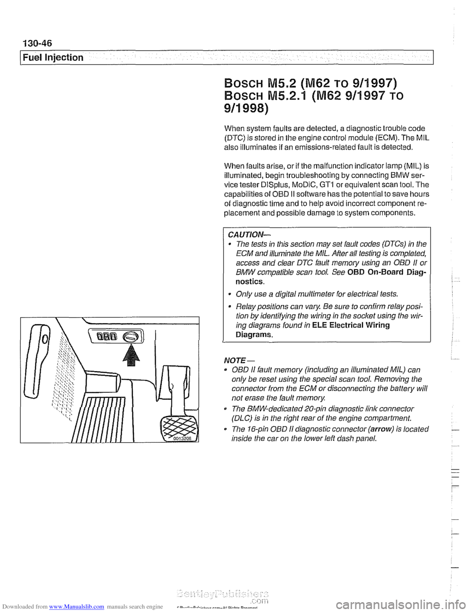
I1 diagnostic connector (arrow) is located
inside the car on
the lower left dash panel.
Page 439 of 1002
Downloaded from www.Manualslib.com manuals search engine
- Fuel Injection
ECM relay, testing
The engine control module (ECM) relay is energized via the
ECM and supplies battery positive
(B+) power to many of the
engine
management components and subsystems. If this re-
lay is faulty, the engine will not start.
CAUTIOI\C
Relay positions can vary. Be sure to confirm relay position by
identifying the wiring
in the socket using the wiring diagrams
in ELE Electrical Wiring Diagrams.
NOTE-
The ECM relay is also referred to as the DME main relay.
ECM relay powers:
* ECM
Ignition coils
Fuel injection
Evaporative leak detection pump
(5.2.1 only)
Idle air actuator
Camshaft sensors Evaporative emissions valve
Hot film mass air flow sensor
Fuel pump relay
Oxygen sensor heaters
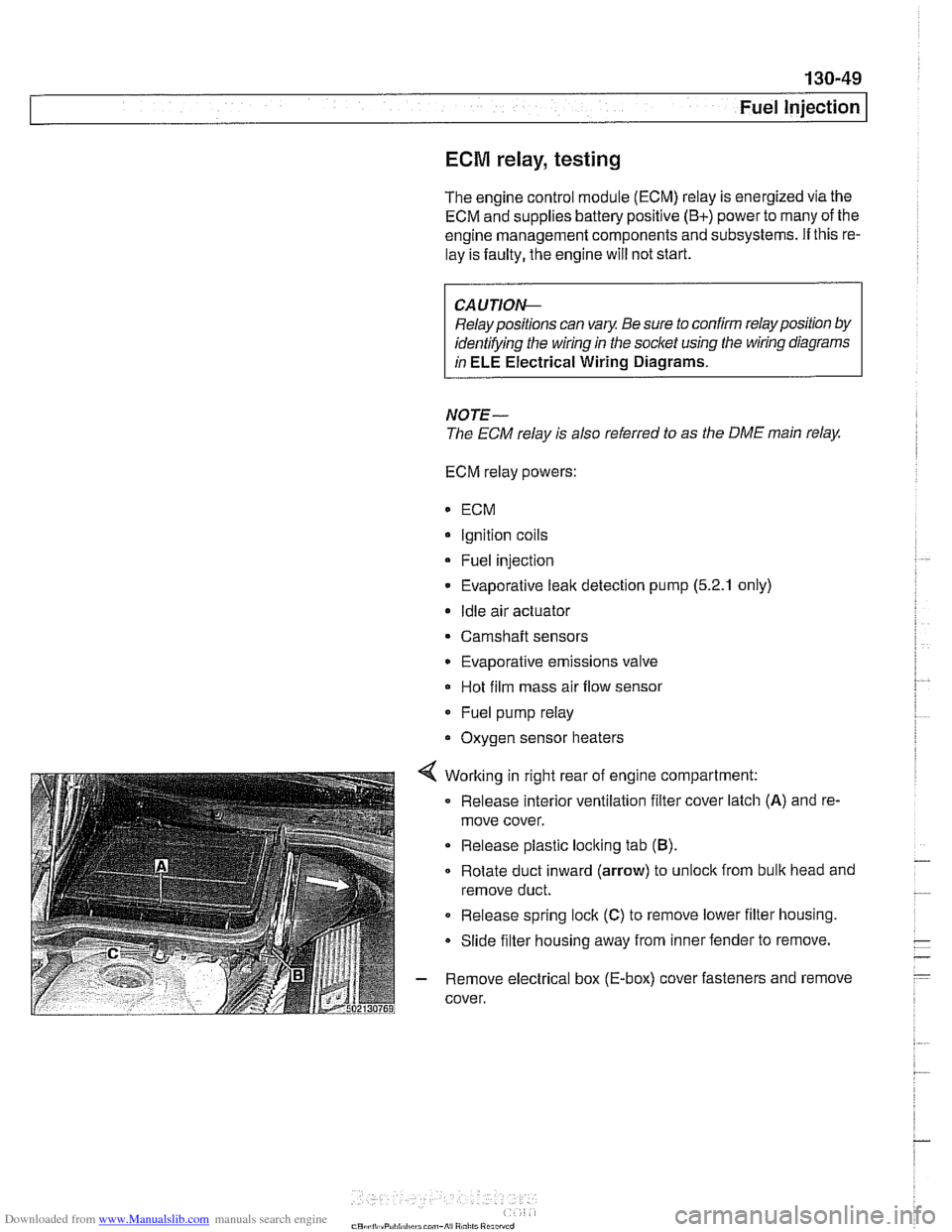
4 Working in right rear of engine compartment:
Release interior ventilation filter cover latch
(A) and re-
move cover.
Release plastic locking tab
(B).
Rotate duct inward (arrow) to unloclc from bulk head and
remove duct.
0 Release spring lock (C) to remove lower filter housing.
Slide filter housing away from inner fender to remove.
- Remove electrical box (E-box) cover fasteners and remove
cover.
Page 440 of 1002
Downloaded from www.Manualslib.com manuals search engine
130-50
Fuel Injection
Bosch M5.2
ECM relay
1 HoL al ail iirnel XOL a1 ail limes
i--[-----i F109 (BOA) electronics I L.$.....: .I:
ECM relay . . . . . . . . . ,
8,s
:,
6 1 .. ... ~~.~~. . ...... .-, Engine control ii~~-~.~~..~ ........ ~~~~~~.~~~~:. module relay -;I
Of?
,c,;,,,
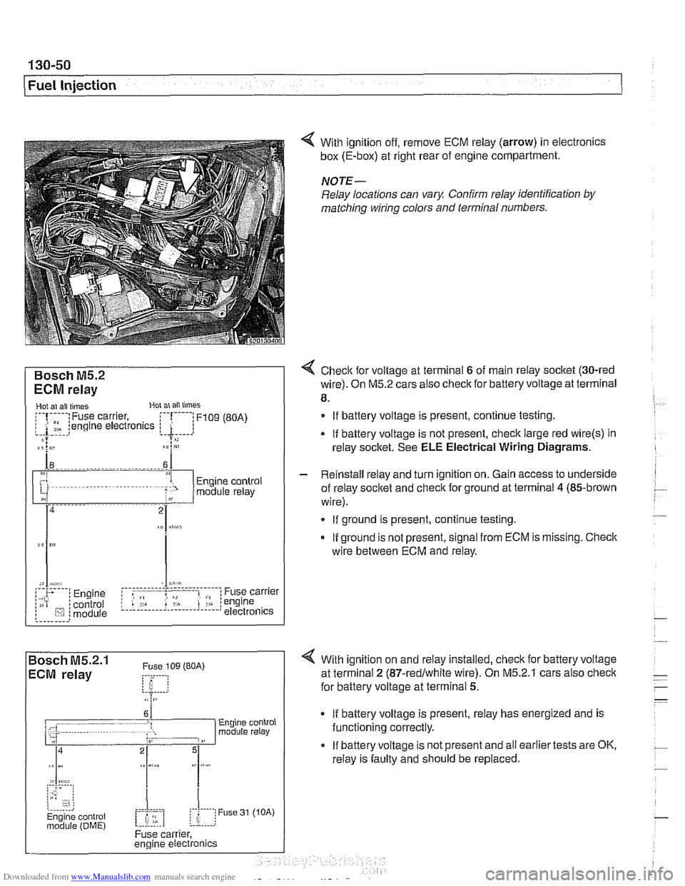
< With ignition off, remove ECM relay (arrow) in electronics
box (E-box) at right rear of engine compartment.
NOTE-
Relay locations can vary. Conh relay identification by
matcliing wiring colors and terminal numbers.
4 Check for voltage at terminal 6 of main relay socket (30-red
wire). On M5.2 cars also check for battery voltage at terminal
8.
. . . . . . . . . ,
If battery voltage is present, continue testing
.
If battery voltage is not present, check large red wire(s) in
relay socltet. See
ELE Electrical Wiring Diagrams.
%P,,tt
- Reinstall relay and turn ignition on. Gain access to underside
of relay socket and
checlc for ground at terminal 4 (85-brown
wire).
. . . . . . . . . . . . - - - - - - - - - . - - - . . l ,,-. ; Engine i f .: , ; Fuse carrier .,A . :engine /;is? /control L.!.!! .... 1.: ...... !.::..! I lij :module electronics If
ground is present, continue testing
If ground is not present, signal from ECM is missing. Checic
wire between ECM and relay.
4 With ignition on and relay installed, check for battery voltage
at terminal
2 (87-redlwhite wire). On M5.2.1 cars also checlc
for battery voltage at terminal 5.
If battery voltage is present, relay has energized and is
functioning correctly.
If battery voltage is not present and all earlier tests are OK,
relay is faulty and should be replaced.
Page 448 of 1002
Downloaded from www.Manualslib.com manuals search engine
Fuel Injection Evaporative fuel system pressure leak
diagnosis, overview
(M5.2.1 only)
1998 540i models are equipped with an evaporative fuel sys-
tem pressure leak diagnosis system. The main component of
this system is the leak diagnosis pump (LDP). The function of
the LDP is to pressurize the fuel tank and the evaporative
emission system for the purpose of detecting
leaks. This sys-
tem is capable of detecting a leak as small as 0.5 mm.
The LDP, located in the left rear wheel housing, is a unitized
component that contains the following:
Vacuum chamber. Pneumatic pump chamber.
DME activated vacuum solenoid
Reed switch (provides switched voltage
feedback signal to
ECM).
The vacuum supply line is in the wiring harness from the en-
gine compartment and runs down the driver's side of the vehi-
cle.
The canister vent valve is integrated into the LDP, which is
electrically controlled by the ECM. The canister vent valve is
opened to provide fresh air entry into the fuel system only dur-
ing purge operation.
- Purge operation characteristics:
Off idle through full throttle: purge valve opened by pulse
width modulated (PWM) control of the ECM. PWM duty cy-
cle varies by engine operating conditions
(e.g. warm idle,
purge valve opened slightly; cold
idleldecel with engine
temp
< 67" C, purge valve always closed).
Page 456 of 1002
Downloaded from www.Manualslib.com manuals search engine
Fuel Injection
When system faults are detected, a diagnostic trouble code
(DTC) is stored in the engine control module (ECM). The MIL
also illuminates
if an emissions-related fault is detected.
When faults arise, or
if the malfunction indicator lamp (MIL) is
illuminated, begin troubleshooting by connecting BMW ser-
vice tester
DISplus, MoDiC, GTl or equivalent scan tool. The
capabilities of OBD
II software has the potential to save hours
of diagnostic time and to help avoid incorrect component re-
placement and possible damage to system components.
CA UTIOI\C
The tests in this section may set fault codes (DTCs) in the
ECM and illuminate the MIL. After all testing is completed,
access and clear DTC fault memory using an OBD
I1 or
BMW compatible scan tool. See OBD On-Board Diag-
nostics.
. Only use a digital multimeter for electrical tests.
Relay positions can vary. Be sure to confirm relay posi-
tion by identifying the wiring in the
socket using the wir-
ing diagrams found in ELE Electrical Wiring
Diaqrams.
NOTE-
= OBD I1 fault memory (including an illuminated MIL) can
only be reset using the special scan tool. Removing the
connector from the ECM or disconnecting the battery will
not erase the fault memory.
0 The BMW-dedicated 20-pin diagnostic link connector
(DLC) is in the right rear of the engine compartment. The
20-pin DLC was eliminated on models after
6/2000.
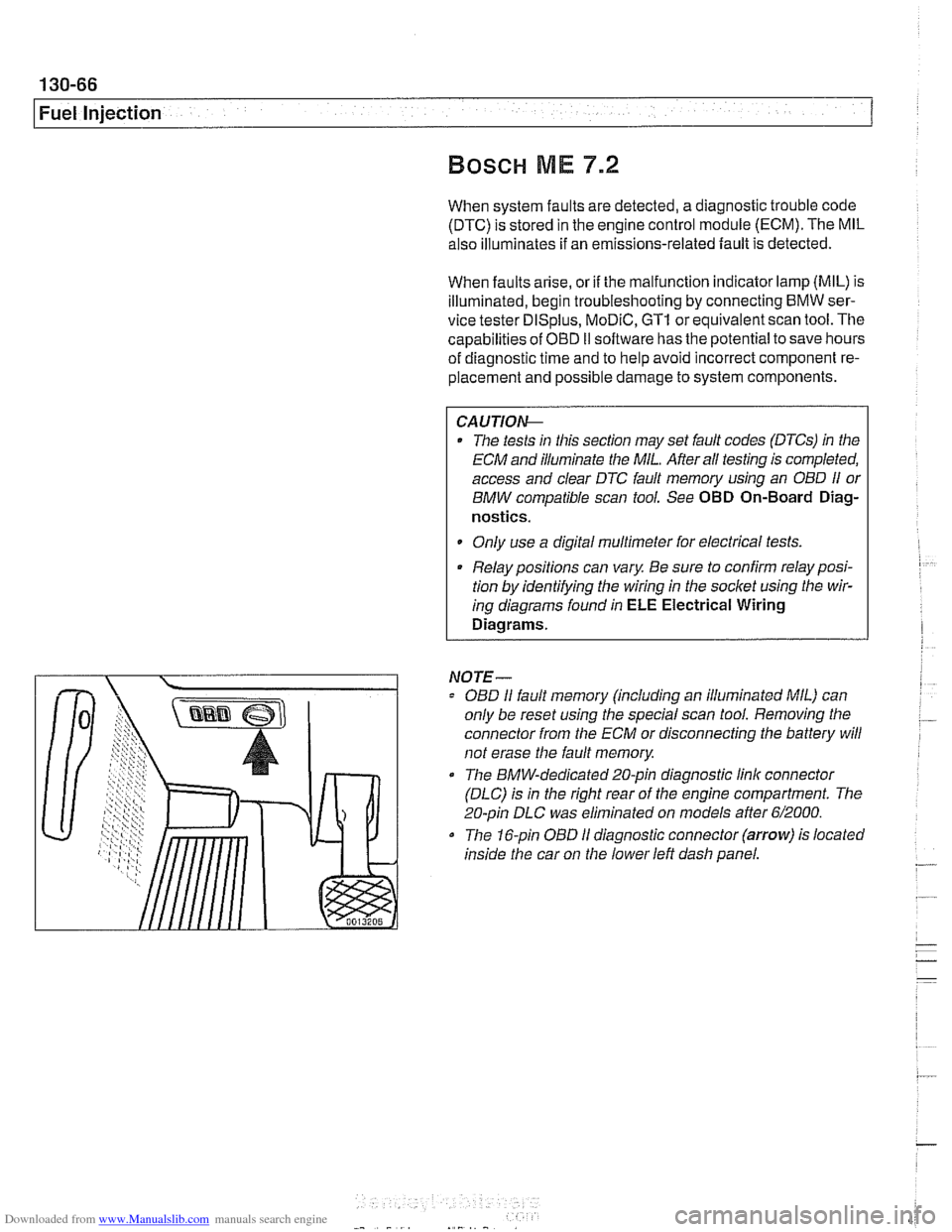
The 16-pin OBD I1 diagnostic connector (arrow) is located
inside the car on the lower left dash panel.
Page 460 of 1002
Downloaded from www.Manualslib.com manuals search engine
130-70
Fuel Injection
ECM relay
--
CAUTION-
Relay positions can vary Be sure to confirm relay position by
identifying the wiring in the
socl(et using the wiring diagrams
in ELE Electrical Wiring Diagrams.
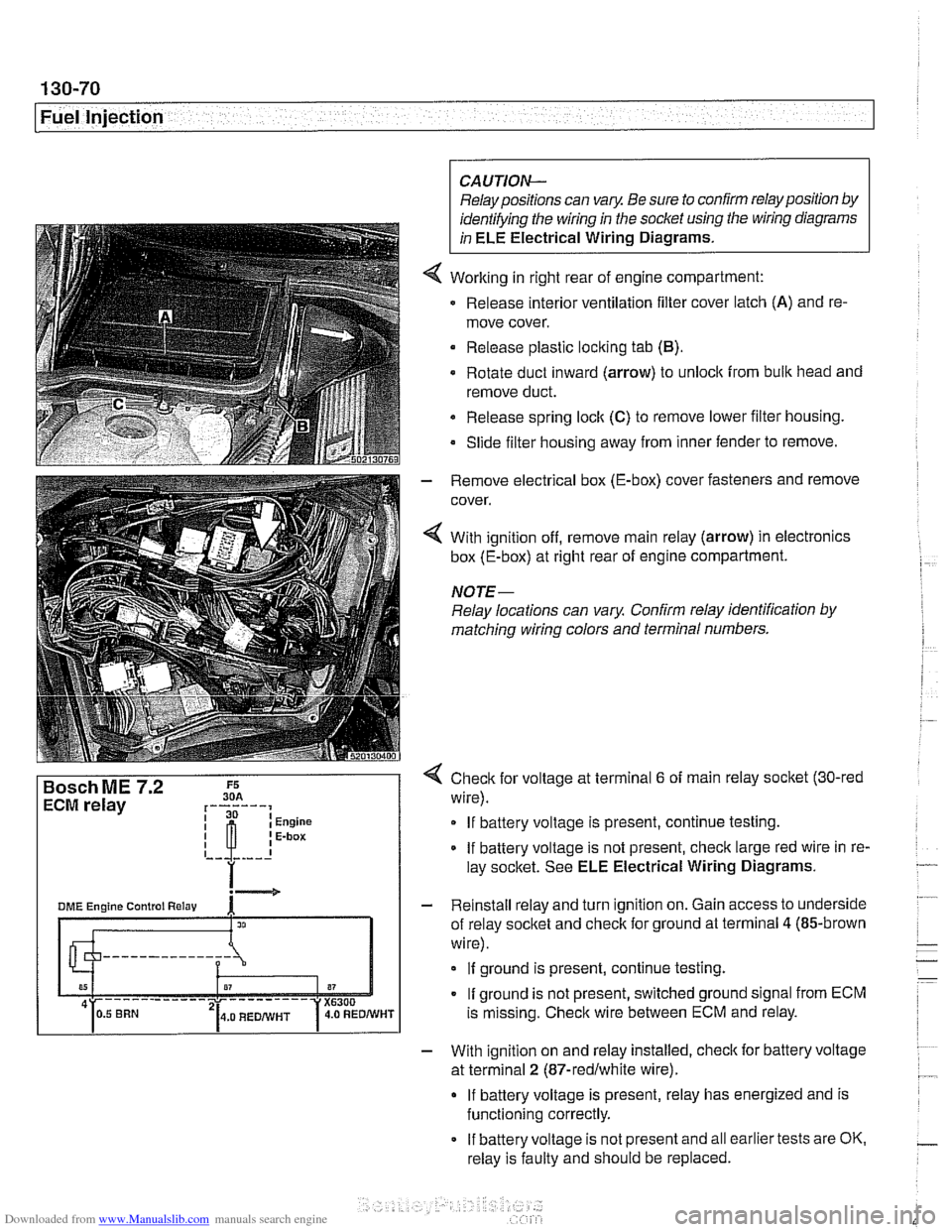
Working in right rear of engine compartment:
Release interior ventilation filter cover latch
(A) and re-
move cover.
Release plastic locking tab
(B).
Rotate duct inward (arrow) to unlock from bulk head and
remove duct.
Release spring
loclt (C) to remove lower filter housing.
Slide filter housing away from inner fender to remove.
- Remove electrical box (E-box) cover fasteners and remove
cover.
4 With ignition off, remove main relay (arrow) in electronics
box (E-box) at right rear of engine compartment.
NOTE-
Relay locations can vary Confirm relay identification by
matching wiring colors and terminal numbers.
4 Check for voltage at terminal 6 of main relay socket (30-red
wire).
If battery voltage is present, continue testing.
If battery voltage is not present, check large red wire in re-
lay socltet. See ELE Electrical Wiring Diagrams.
- Reinstall relay and turn ignition on. Gain access to underside
of relay socket and check for ground at terminal
4 (85-brown
wire).
If ground is present, continue testing.
If ground is not present, switched ground signal from ECM
is missing. Check wire between ECM and relay.
- With ignition on and relay installed, check for battery voltage
at terminal
2 (87-redlwhite wire).
If battery voltage is present, relay has energized and is
functioning correctly.
If battery voltage is not present and all earlier tests are OK.
relay is faulty and should be replaced.