Section 6 BMW 528i 1998 E39 Workshop Manual
[x] Cancel search | Manufacturer: BMW, Model Year: 1998, Model line: 528i, Model: BMW 528i 1998 E39Pages: 1002
Page 12 of 1002
Downloaded from www.Manualslib.com manuals search engine
01 0-2
General
This section is intended to help the do-it-yourselfer get start-
ed. Tips on workshop practices, basic tools, and a quick refer-
ence guide to emergencies can be found here.
WARNING-
Do not use this manual unless you are familiar with basic
automotive repair procedures and safe workshop
practices.
0 This manual illustrates the worl
and up-to-date information from the vehicle manufac-
turer or for proper training as an automotive technician.
Note that it is not possible to anticipate all of the ways
or conditions under which vehicles may be serviced or
to provide cautions as to all of the possible hazards that
may result.
MOW TO USE THIS MANUAL
WARNING -
Your common sense and goodjudgement are crucial to safe
and successful service
work. Read procedures through be-
fore starting them. Think about whether the condition of your
cac your level of mechanical skill, or pour level of reading
comprehension might result in or contribute in some way to
an occurrence that might cause you injury, damage your car;
or result in an unsafe repair. If you have doubts for these or
other reasons about your ability to perform safe repair work
on your car; have the work done at an authorized
BMW deal-
er or other qualified shop.
The manual is divided into ten sections:
0 GENERAL, MAINTENANCE
0 I ENGINE
2 TRANSMISSION
3 SUSPENSION, STEERING AND BRAKES
4 BODY
5 BODY EQUIPMENT
6 ELECTRICAL SYSTEM
7 EQUIPMENT AND ACCESSORIES
- ELE ELECTRICAL WIRING DIAGRAMS
OBD ON-BOARD DIAGNOSTICS
Page 13 of 1002

Downloaded from www.Manualslib.com manuals search engine
General
0 GENERAL, MAINTENANCE covers general vehicle infor-
mation
(010 General) as well as the recommended mainte-
nance schedules and service procedures to perform BMW
scheduled maintenance
work (020 Maintenance).
The next seven sections
(1 through 7) are repair based and
organized by three digit repair groups. Most major sections
begin with a GENERAL repair group,
e.g. 100 Engine-Gen-
eral. These "00 (double zero) groups contain descriptive the-
ory of operation and system troubleshooting information. The
remainder of the repair groups within a section contain the
service and repair information. The last two sections contain
detailed electrical wiring schematics and OBD
II scan tool and
diagnostic information.
Warnings, cautions and notes
Throughout this manual are many passages with the head-
ings WARNING, CAUTION, or NOTE. These very important
headings have different meanings.
WARNING-
The text under this heading warns of unsafe practices that
are very
likely to cause injury, either by direct threat to the per-
son(~) performing the work
orby increasedrisl( of accident or
mechanical failure while
drivinq.
CAUTION-
A CAUTION calls attention to importantprecautions to be ob-
senfed during the repair work that will help prevent acciden-
tally damaging the car or its parts.
NOTE-
A NOTE contains helpful information, tips that will help in do-
ing a betterjob and completing it more easily.
Please read every WARNING, CAUTION, AND NOTE in
001
General Warnings and Cautions and as they appear in re-
pair procedures. They are very important. Read them before
you begin any maintenance or repair job.
Page 46 of 1002
Downloaded from www.Manualslib.com manuals search engine
020-1 4
Maintenance
- When oil flow has diminished to an occasional drip, reinstall
drain plug with a new metal sealing washer and torque plug.
Tightening torque Engine oil drain plug to oil pan
25 Nrn (1.8 ft-lb)
6-cylinder oil filter assembly
r------ 1
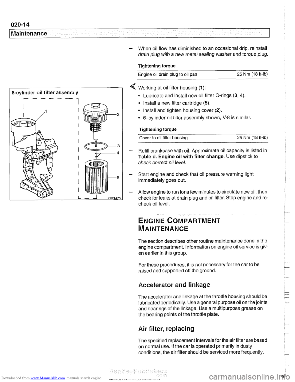
< Working at oil filter housing (1):
Lubricate and install new oil filter O-rings (3, 4).
Install a new filter cartridge (5).
lnstall and tighten housing cover (2).
6-cylinder oil filter assembly shown, V-8 is similar.
Tightening torque Cover to oil filter housing
25 Nm (1.8 it-lb)
- Refill crankcase with oil. Approximate oil capacity is listed in
Tabled. Engine oil with filter change. Use dipstick to
check correct oil level.
- Start engine and check that oil pressure warning light
immediately goes out.
- Allow engine to run fora few minutes to circulate new oil, then
check for leaks at drain plug and oil filter. Stop engine and re-
check oil level
The section describes other routine maintenance done in the
engine compartment. Information on engine oil service is
giv-
enkar~ier inthis group.
For these procedures, it is not necessary for the car to be
raised and supported off the ground.
Accelerator and linkage
The accelerator and linkage at the throttle housing should be
lubricated periodically. Use ageneral purposeoil on the joints
and bearings of the linkage. Use a multipurpose grease on
the bearing points of the throttle plate.
Air filter, replacing
The specified replacement intervals forthe air filter are based
on normal use. If the car is operated primarily in dusty
conditions, the air filter should be serviced more frequently.
Page 48 of 1002
Downloaded from www.Manualslib.com manuals search engine
020-1 6
Maintenance
loose, hose is damaged, or connection is dirty or corroded.
Dried coolant has achalky appearance. Hoses should be firm
and springy. Replace any hose that is cracked, has become
soft and limp, or has been contaminated by oil.
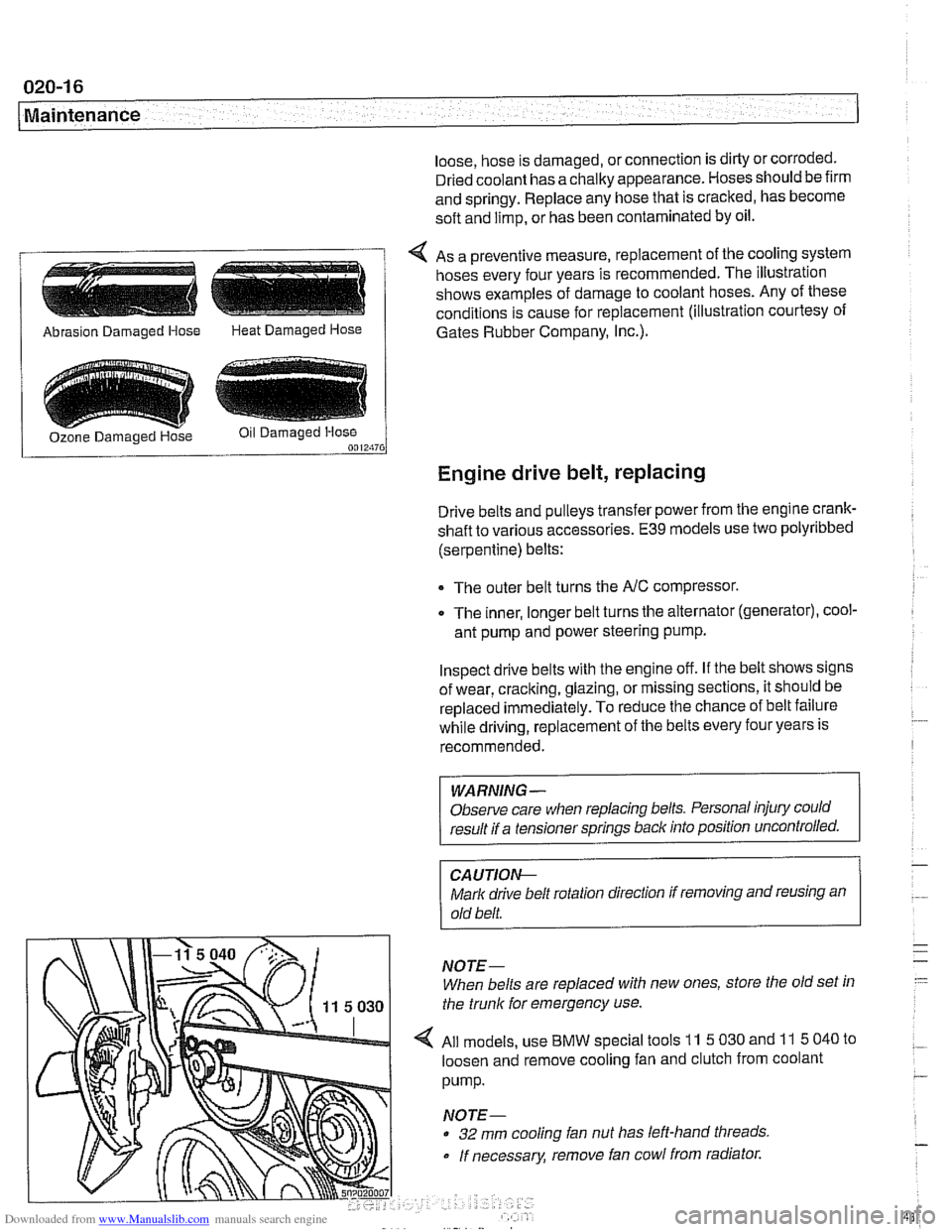
4 As a preventive measure, replacement of the cooling system
hoses every four years is recommended. The illustration
shows examples of damage to coolant hoses. Any of these
conditions is cause for replacement (illustration courtesy of
/ Abrasion Damaged Hose Heat Damaged Hose 1 Gates Rubber Company, I~c.).
Engine drive belt, replacing
Drive belts and pulleys transfer power from the engine crank-
shaft to various accessories.
E39 models use two polyribbed
(serpentine) belts:
The outer belt turns the
NC compressor.
0 The inner, longer belt turns the alternator (generator), cool-
ant pump and power steering pump.
Inspect drive belts with the engine off. If the belt shows signs
of wear, cracking, glazing, or missing sections, it should be
replaced
immediately. To reduce the chance of belt failure
while driving, replacement of the belts every four years is
recommended.
WARNING -
Observe care when replacing belts. Personal injury could
result if a tensioner springs back into position uncontrolled.
CA UTIOI\C
Mark drive belt rotation direction if removing and reusing an
old belt.
NOTE-
When belts are replaced with new ones, store the old set in
the trunk for emergency use.
All models, use
BMW special tools 11 5 030 and 11 5 040 to
loosen and remove cooling fan and clutch from coolant
pump.
NOTE-
32 mm cooling fan nut has left-hand threads
If necessary, remove fan cowl from radiator.
Page 68 of 1002
Downloaded from www.Manualslib.com manuals search engine
Engine-General
This section covers system descriptions and general informa-
tion on engines and engine management systems. Also cov-
ered is basic engine troubleshooting.
For specific repair procedures, refer to the appropriate repair
group:
110 Engine Removal and Installation
0 113 Cylinder Head Removal and Installation
116 Cylinder Head and Valvetrain
0 117 Camshaft Timing Chain
119 Lubrication System
120 Ignition System
130 Fuel Injection
0 170 Radiator and Cooling System
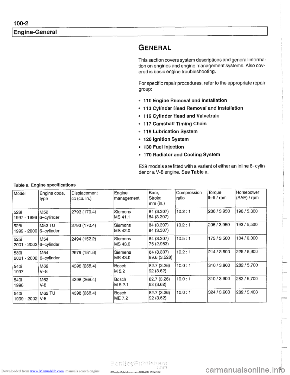
E39 models are fitted with a variant of either an inline 6-cylin-
der or a
V-8 engine. See Table a.
Table a. Engine specifications
Page 161 of 1002
Downloaded from www.Manualslib.com manuals search engine
1 13-67
Cylinder Head Removal and lnstaKI --
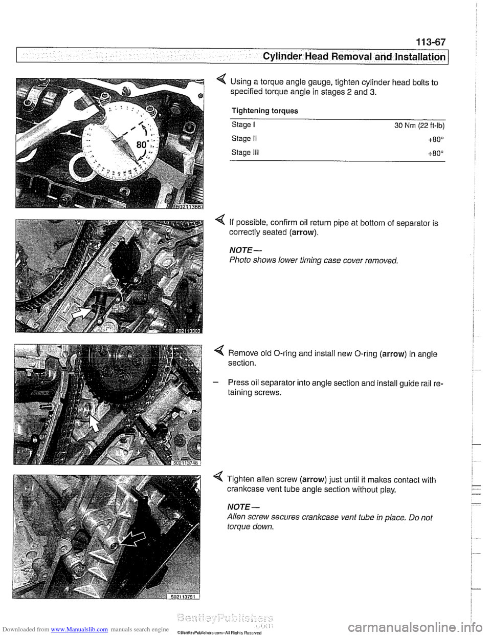
< Using a torque angle gauge, tighten cylinder head bolts to
specified torque angle in stages
2 and 3.
Tightening torques
Stage I 30 Nrn (22 ft-lb)
Stage II +80°
Stage Ill +80°
4 If possible, confirm oil return pipe at bottom of separator is
correctly seated
(arrow).
NOTE-
Photo shows lower timing case cover removed.
< Remove old O-ring and install new O-ring (arrow) in angle
section.
- Press oil separator into angle section and install guide rail re-
taining screws.
4 Tighten allen screw (arrow) just until it makes contact with
crankcase vent tube angle section without play.
NOTE-
Allen screw secures crankcase vent tube in place. Do not
torque down.
Page 181 of 1002
Downloaded from www.Manualslib.com manuals search engine
11 6-5
I Cylinder Head and valvetrain1
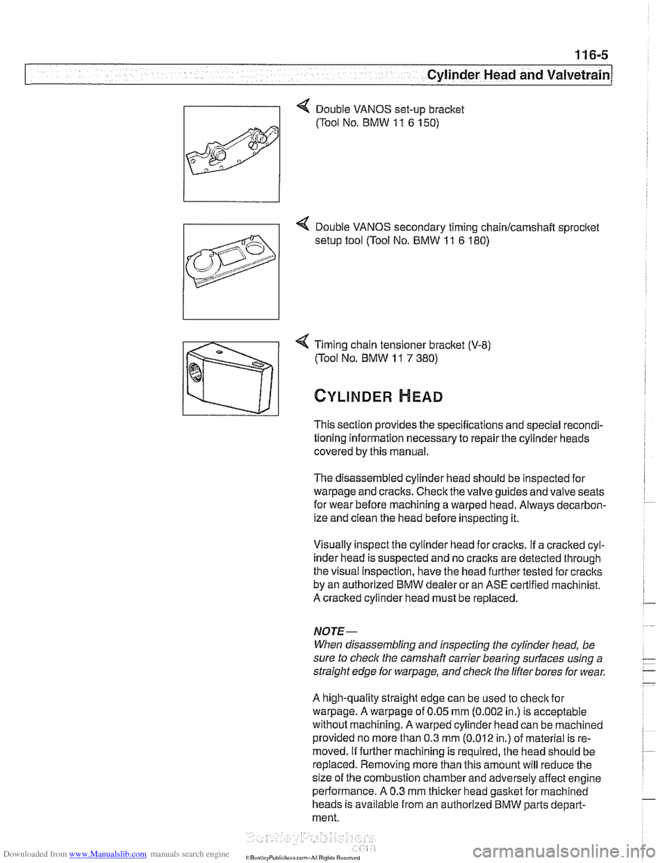
4 Timing chain tensioner bracket (V-8)
(Tool No. BMW
11 7 380)
CYLINDER HEAD
This section provides the specifications and special recondi-
tioning information necessary to repair the cylinder heads
covered by this manual.
The disassembled cylinder head should be inspected for
warpage and cracks. Check the valve guides and valve seats
for wear before machining a warped head. Always decarbon-
ize and clean the head before inspecting it.
Visually inspect the cylinder head for craclts.
If a cracked cyl-
inder head is suspected and no
craclts are detected through
the visual Inspection, have the head further tested for cracks
by an authorized BMW dealer or an ASE certified machinist.
A cracked cylinder head must be replaced.
NOJE-
When disassembling and inspecting the cylinder head, be
sure to
checlc the camshaft carrier bearing surfaces using a
straight edge for
warpage, and check the lifter bores for wear.
A high-quality straight edge can be used to
checlc for
warpage. A warpage of 0.05 mm (0.002 in.) is acceptable
without machining. A warped cylinder head can be machined
provided no more than 0.3
mm (0.012 in.) of material is re-
moved.
If further machining is required, the head should be
replaced. Removing more than this amount will reduce the
size of the combustion chamber and adversely affect engine
performance. A 0.3 mm
thicker head gasket for machined
heads is available from an authorized BMW parts depart-
ment.
Page 183 of 1002
Downloaded from www.Manualslib.com manuals search engine
Cylinder Head and valvetrain1
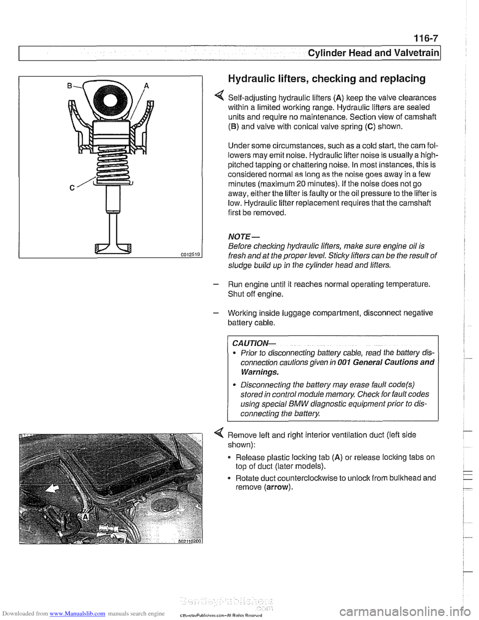
Hydraulic lifters, checking and replacing
Self-adjusting hydraulic lifters (A) keep the valve clearances
within a limited working range. Hydraulic lifters are sealed
units and require no maintenance. Section view of camshaft
(6) and valve with conical valve spring (C) shown.
Under some circumstances, such as a cold start, the cam fol-
lowers may emit noise. Hydraulic lifter noise is usually a
high-
pitched tapping or chattering noise. In most instances, this is
considered normal as long as the noise goes away in a few
minutes (maximum
20 minutes). If the noise does not go
away, either the lifter is faulty or the oil pressure to the lifter is
low. Hydraulic lifter replacement requires that the camshaft
first be removed.
NOTE-
Before checking hydraulic lifters, male sure engine oil is
fresh and at the proper level.
Sticky lifters can be the result of
sludge build up in the cylinder head and lifters.
- Run engine until it reaches normal operating temperature.
Shut off engine.
- Working inside luggage compartment, disconnect negative
battery cable.
CAUTION-
Prior to disconnecting battery cable, read the baltery dls-
connection cautions given In 001 General Cautions and
Warnings.
Disconnecting the battery may erase fault
code(s)
stored in control module memory Check for fault codes
4 Remove left and right interior ventilation duct (left side
shown):
Release plastic locking tab
(A) or release loclting tabs on
top of duct (later models).
Rotate duct counterclockwise to
unloclt from bulithead and
remove (arrow).
Page 232 of 1002
Downloaded from www.Manualslib.com manuals search engine
1 16-56
Cylinder Head and Valvetrain
This section covers valve removal and reconditioning, includ-
ing valve guides, seats, springs, and valve stem oil seals.
Valves, leak test
To test the valves for leakage, the cylinder head must be dis-
assembled with camshafts and camshaft carriers removed.
With valve assemblies and spark plugs installed, place the
cylinder head on a workbench with the combustion chamber
facing upward. Fill each combustion chamber with a thin non-
flammable liquid. After fifteen minutes,
check the level of the
fluid. If the fluid level in any cylinder drops, that cylinder is not
sealing properly.
Valves, removing and installing
- Remove cylinder head as described in 113 Cylinder Head
Removal and Installation.
CAUTIOI\C
(M52 TU/M54 engines only) Do not let the hydraulic lifters
fall out as the camshaft carrier is removed. Special suction
cups are available from
BMW to hold the hydraulic lifters in
place during carrier removal.
* Hydraulic cam lifters should be stored m an uprfght po-
sition. If necessary, use a magnetic tool to
aidin remov-
al of the lifters.
- Remove valves using a valve spring compressor.
CAUTIOI\C
Label each valve assembly as it is removed so it can be in-
stalled in its original position.
-
- Remove and discard valve stem oil seals from valve guides.
See Valve stem oil seals later in this section.
- Valve installation is reverse of removal. Remove carbon de- - -
posits from the valves using a wire brush or wire wheel. -
-
Valve specifications are listed in Table c. Valve specifica-
tions.
Page 319 of 1002
Downloaded from www.Manualslib.com manuals search engine
Camshaft Timing chain/
- Tighten accessible sprocket retaining bolts in the following
order:
Leit exhaust camshaft
Right exhaust
camshait
Leit intake camshaft
Right
intalte camshait
Tightening torque
Sprocket bolts to camshaft flange
15 Nm (1 1 ft-lb)
- Remove BMW special tool 11 2 300 from tool bore at bell-
housing and remove
camshaft loclting tools from cylinder
heads.
Using crankshaft center bolt, turn engine over clockwise at
least one
comolete rotation so that remainino camshaft
sprocltet
retaking bolts are accessible. -
- Tighten remaining camshait sprocket retaining bolts
Tightening torque Sprocket bolts to camshaft
flange 15 Nm (I 1 It-lb)
- Remove BMW special tool 11 3 390 from primary timing
chain tensioner bore and reinstall primary chain tensioner
- Remainder of installation is reverse or removal, noting the fol-
lowing:
Remove gasket residue from cylinder head sealing sur-
face.
Apply a thin bead of Three Bond 1209
O sealing com-
pound to joints at cylinder head cover and timing case cov-
er and at half-moon sections at rear of cylinder heads.
Replace cylinder head cover
gaskets if necessary.