bolt BMW 528i 1999 E39 Workshop Manual
[x] Cancel search | Manufacturer: BMW, Model Year: 1999, Model line: 528i, Model: BMW 528i 1999 E39Pages: 1002
Page 736 of 1002
Downloaded from www.Manualslib.com manuals search engine
330-40
Rear Suspension
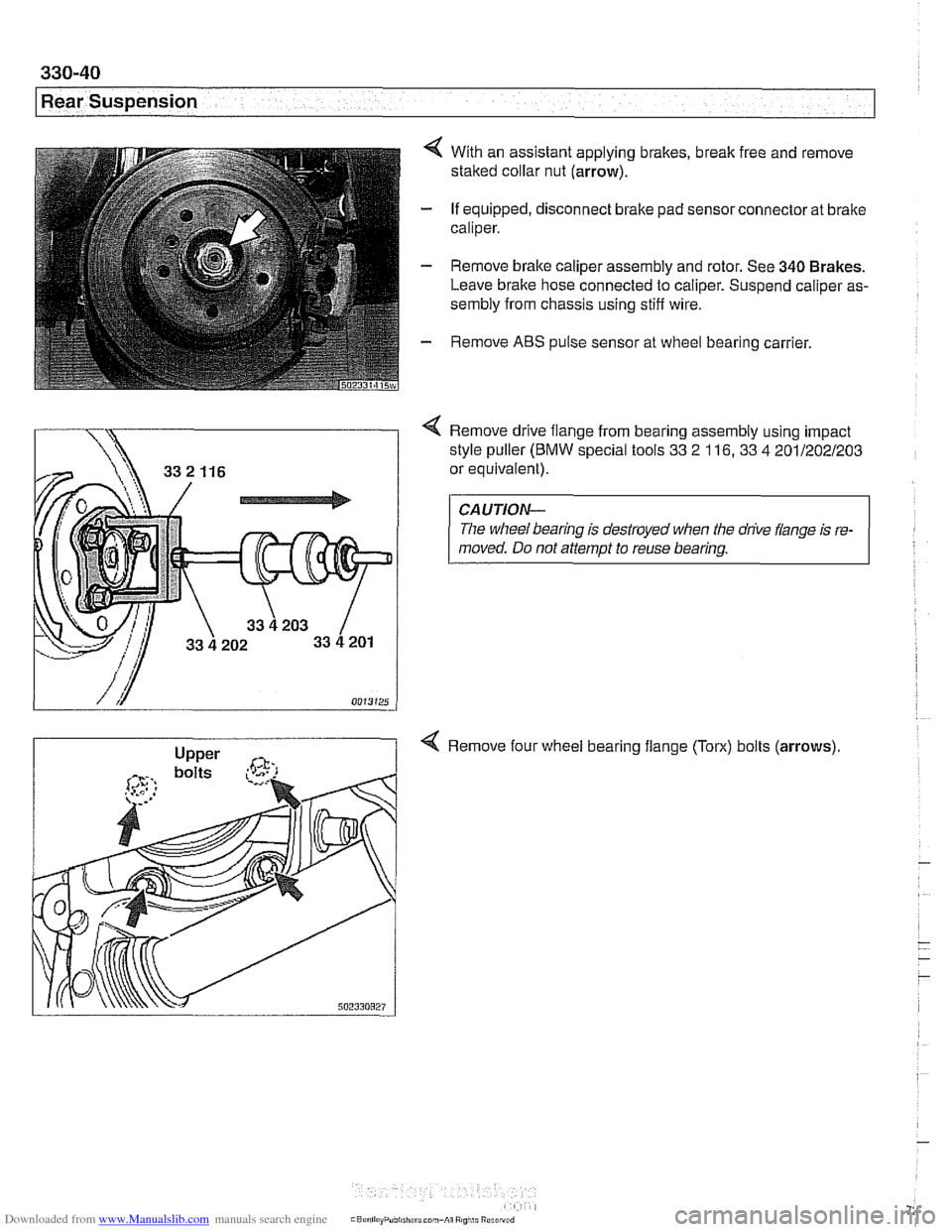
4 With an assistant applying brakes, break free and remove
staked collar nut (arrow).
- If equipped, disconnect brake pad sensor connector at brake
caliper.
- Remove brake caliper assembly and rotor. See 340 Brakes.
Leave brake hose connected to caliper. Suspend caliper as-
sembly from chassis using stiff wire.
- Remove ABS pulse sensor at wheel bearing carrier.
Remove drive flange from bearing assembly using impact
style puller
(BMW special tools 33 2 116, 33 4 201/202/203
or equivalent).
CAUTION-
The wheel bearing is destroyed when the drive flange is re-
moved. Do not attempt to reuse bearing.
4 Remove four wheel bearing flange (Torx) bolts (arrows)
Page 737 of 1002
Downloaded from www.Manualslib.com manuals search engine
--. ..
Rear Suspension
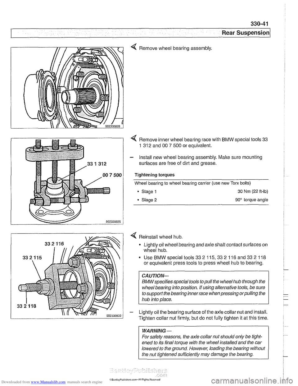
4 Remove wheel bearing assembly.
4 Remove inner wheel bearing race with BMW special tools 33
1 312
and 00 7 500 or equivalent.
- Install new wheel bearing assembly. Malte sure mounting
surfaces are free of dirt and grease.
Tightening torques
Wheel bearing to wheel bearing carrier (use new
Tom bolts)
Stage
1 30 Nm (22 ft-lb)
Stage 2 90" torque angle
4 Reinstall wheel hub.
Lightly oil wheel bearing and axle shaft contact surfaces on
wheel hub.
Use BMW special tools
33 2 115,33 2 116 and 33 2 118
or equivalent press tools to press wheel hub to bearing.
CAUTION-
BMWspecifies speclaltools to pull the wheel hub through the
wheel bearing into position. If using alternative tools, be sure
to support the bearing inner race when pressing orpulling the
hub into place.
- Lightly oil the bearing surface of the axle collar nut and install.
Tighten collar nut firmly, but do not fully tighten it at this time.
WARNING-
For safety reasons, the axle collar nut should only be tight-
ened to its final torque with the wheel installed and the car
lowered to the ground. However, loading the bearing without
the nut tightened sufficiently may damage
the bearing.
Page 740 of 1002
Downloaded from www.Manualslib.com manuals search engine
---
Rear Suspension
ELECTRONIC HEIGHT CONTROL
(EHC) COMPONENT REPLACEMENT
Sport Premium rear suspension is an option on Sport Wagon
models and standard on
1999 and later V-8 Sport Wagons.
This suspension incorporates electronic height control
(EHC)
using air springs.
With vehicle lifted off the ground,
if the rear air springs can be
compressed by hand, either the spring is defective or the sys-
tem is depressurized.
Locate
EHC faults using BMW scan tools DIS or MoDiC. EHC
description and some troubleshooting is covered in 300 Sus-
pension, Steering and Brakes-General.
Air spring replacement is covered earlier in this chapter. See
Air spring, removing and installing.
CAUTION-
Maintain high levels of cleanliness around air line connec-
tions when disassembling and assembling air suspension
components. Even
small dirt particles can cause leakage in
the pressurized system.
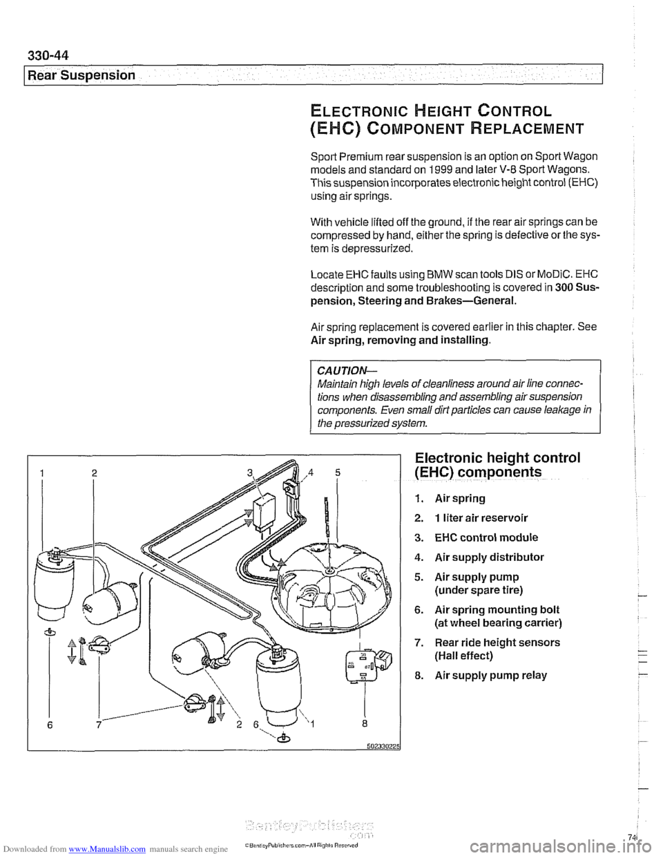
Electronic height control
(EHC) components
1. Air spring
2. 1 liter air reservoir
3. EHC control module
4. Air supply distributor
5. Airsupply pump
(under spare tire)
6. Air spring mounting bolt
(at wheel bearing carrier)
7. Rear ride height sensors
(Hall effect)
8. Air supply pump relay
Page 749 of 1002
Downloaded from www.Manualslib.com manuals search engine
Final Drive
Final drive, removing and installing
- Raise rear of car.
WARNING-
Make sure that the car is firmly supported on jack stands de-
signed for the purpose. Place the jaclc stands beneath struc-
tural chassis
~oints. Do not i lace iaclc stands under
( suspension barfs.
Remove exhaust system. See 180 Exhaust System.
Disconnect drive shaft from final drive. See
260 Driveshaft.
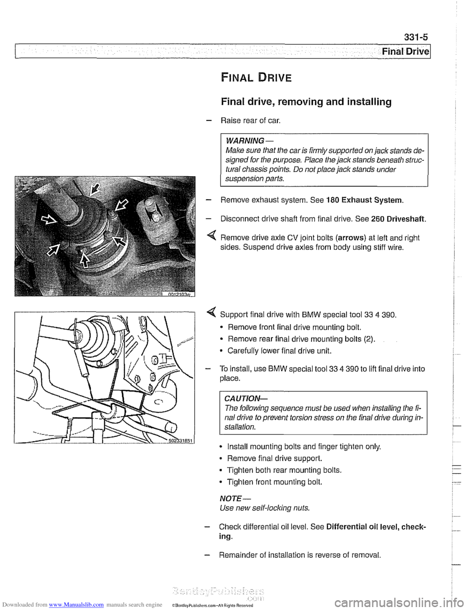
Remove drive axle CV joint bolts (arrows) at left and right
sides. Suspend drive axles from body using stiff wire.
4 Support final drive with BMW special tool 33 4 390.
* Remove front final drive mounting bolt.
Remove rear final drive mounting bolts
(2).
Carefully lower final drive unit.
- To install, use BMW special tool 33 4 390 to lift final drive into
place.
CA UTIOP&
The following sequence must be used when installing the fi-
nal drive to prevent torsion stress on the final drive during in-
Install mounting bolts and finger tighten only.
Remove final drive support.
Tighten both rear mounting bolts.
Tighten front mounting bolt.
NOTE-
Use new self-locking nuts.
- Check differential oil level. See Differential oil level, check-
ing.
- Remainder of installation is reverse of removal.
Page 750 of 1002
Downloaded from www.Manualslib.com manuals search engine
Final Drive
Tightening torques
F~nal drive to rear axle carrier 105 Nm (77 it-lb)
Driveshaft CV joint to final drive flange
- MlO (Torx bolt) 70
Nm (51 ft-lb)
- M8 (compression nut) 32 Nm (24
ft-lb)
Drive axle to final drive
ilange
Torx bolts (M10) 83 Nm (61 ft-lb)
Torx bolt with
rlbbed teeth (M10) 64 Nm (47 ft-lb)
Torx bolt
wlth ribbed teeth (MI0 sliver) 80 Nm (59 ft-lb)
Torx
bolt with ribbed teeth (M10 black) 100 Nm (74 ft-lb)
* Torx bolt with ribbed teeth (M12) 135 Nm (100 ft-lb)
Differential oil level, checking
The E39 differential is filled with lifetime oil that ordinarily
does not need to be changed. BMW recommends using only
a specially formulated synthetic gear oil
(SAF-XO) that is
available through an authorized BMW dealer parts depart-
ment. For additional information on this lubricant and any oth-
er lubricants that may be compatible, contact an authorized
BMW dealer service department.
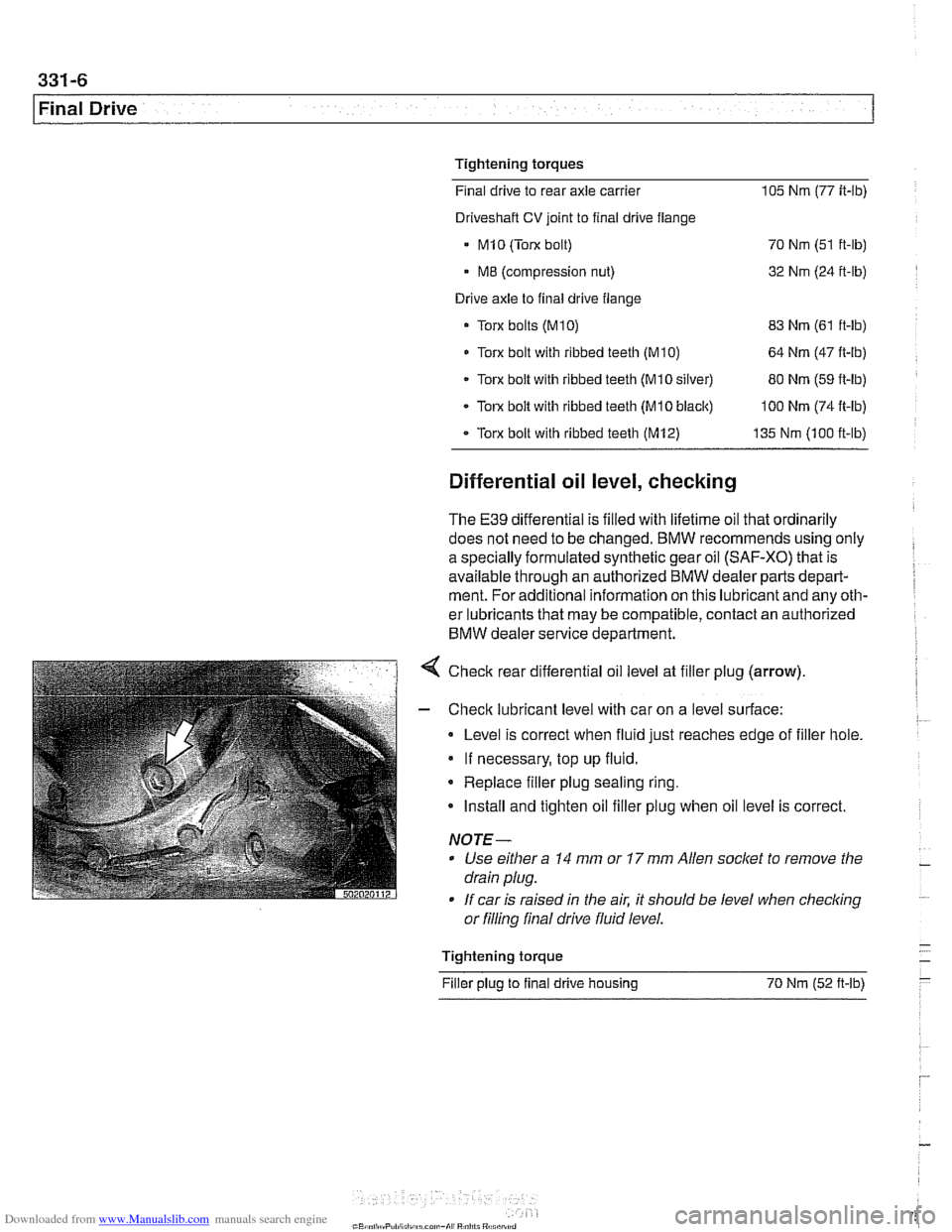
< Check rear differential oil level at filler plug (arrow).
- Check lubricant level with car on a level surface:
Level is correct when fluid just reaches edge of filler hole.
If necessary, top up fluid.
* Replace filler plug sealing ring.
Install and tighten oil filler plug when oil level is correct.
NOTE-
Use either a 14 mm or 17 mm Allen socket to remove the
drain plug.
If car is raised in the air. it should be level when
checkino " or filling final drive fluid level.
- Tightening torque -
Filler plug to final drive housing 70 Nm (52
ft-lb) -
Page 753 of 1002
Downloaded from www.Manualslib.com manuals search engine
331-9
Final Drive
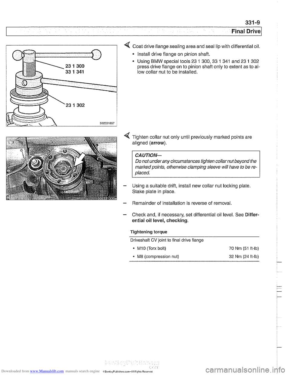
Coat drive flange sealing area and seal lip with differential oil.
* Install drive flange on pinion shaft.
Using
BMW special tools 23 1 300,33 1 341 and 23 1 302
press drive flange on to pinion shaft only to extent as to al-
low collar nut to be installed.
4 Tighten collar nut only until previously marked points are
aligned (arrow).
CAUTION-
Do not underany circumstances tighten collarnut beyond the
markedpoints,
othe~lise clamping sleeve will have to be re-
placed.
- Using a suitable drift, install new collar nut locking plate
Stalte plate in place.
- Remainder of installation is reverse of removal.
- Check and, if necessary, set differential oil level. See Differ-
ential oil level, checking.
Tightening torque Driveshaft
CV joint to final drive flange
MI0 (Torx bolt) 70 Nrn (51 ft-lb)
ME (compression nut) 32 Nrn (24 ft-lb)
Page 754 of 1002
Downloaded from www.Manualslib.com manuals search engine
. .
Final Drive Final drive output shaft seals, replacing
- Remove exhaust system (if necessary). See 180 Exhaust
System.
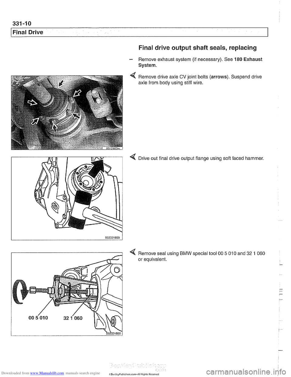
Remove drive axle
CV joint bolts
axle from body using stiff wire. (arrows).
Suspend drive
4 Drive out final drive output flange using soft faced hammer.
4 Remove seal using BMW special tool 00 5 010 and 32 1 060
or equivalent.
Page 755 of 1002
Downloaded from www.Manualslib.com manuals search engine
331-1 1
Final rive(
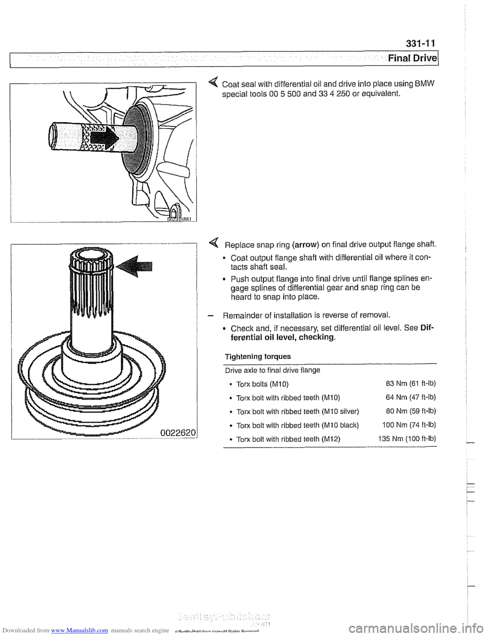
< Coat seal with differential oil and drive into place using BMW
special tools 00 5 500 and 33 4 250 or equivalent.
Replace snap ring (arrow) on final drive output flange shaft.
Coat output flange
shaft with differential oil where it con-
tacts shaft seal.
. Push output flange into final drive until flange splines en-
gage splines of differential gear and snap ring can be
heard to snap into place.
- Remainder of installation is reverse of removal.
Check and, if necessary, set differential oil level. See Dif-
ferential oil level, checking.
Tightening torques Drive axle to final drive flange
Torx bolts
(M10) 83 Nm (61 ft-lb)
Torx bolt with ribbed teeth (M10) 64 Nm (47 it-lb)
Torx bolt with ribbed teeth (Mi0 silver) 80 Nm (59 ft-lb)
Torx bolt with ribbed teeth (MI0 black) 100 Nm (74 ft-lb)
- Torx bolt with ribbed teeth (M12) 135 Nm (100 ft-lb)
Page 758 of 1002
Downloaded from www.Manualslib.com manuals search engine
Final Drive
Drive axles use constant-velocity (CV) joints on both ends.
For replacement parts, only CV joint boots or complete axles
are offered by BMW. The procedure for drive axle removal
varies for sedan and sport wagon. Follow the appropriate pro-
cedure below.
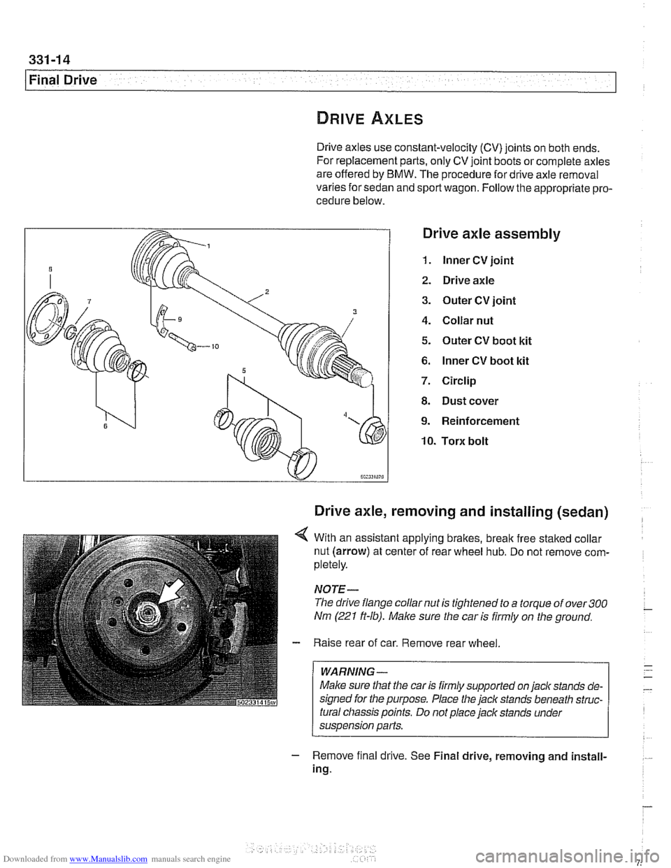
Drive axle assembly
1. lnner CV joint
2. Drive axle
3. Outer CV joint
4. Collar nut
5. Outer CV boot kit
6. lnner CV boot kit
7. Circlip
8. Dust cover
9. Reinforcement
10. Torx bolt
Drive axle, removing and installing (sedan)
4 With an assistant applying brakes, break free staked collar
nut (arrow) at center of rear wheel hub. Do not remove com-
pletely.
NOTE-
The drive flange collar nut is tightened to a torque of over 300
Nm (221 ft-lb). Male sure the car is firmly on the ground.
- Raise rear of car. Remove rear wheel
WARNING -
Make sure that the car is firmly supported on jack stands de-
signed for the purpose. Place the
jack stands beneath struc-
tural chassis points. Do not place jack stands under
suspension parts.
- Remove f~nal drrve. See Final drive, removing and install-
ing.
Page 759 of 1002
Downloaded from www.Manualslib.com manuals search engine
Final ~rivel
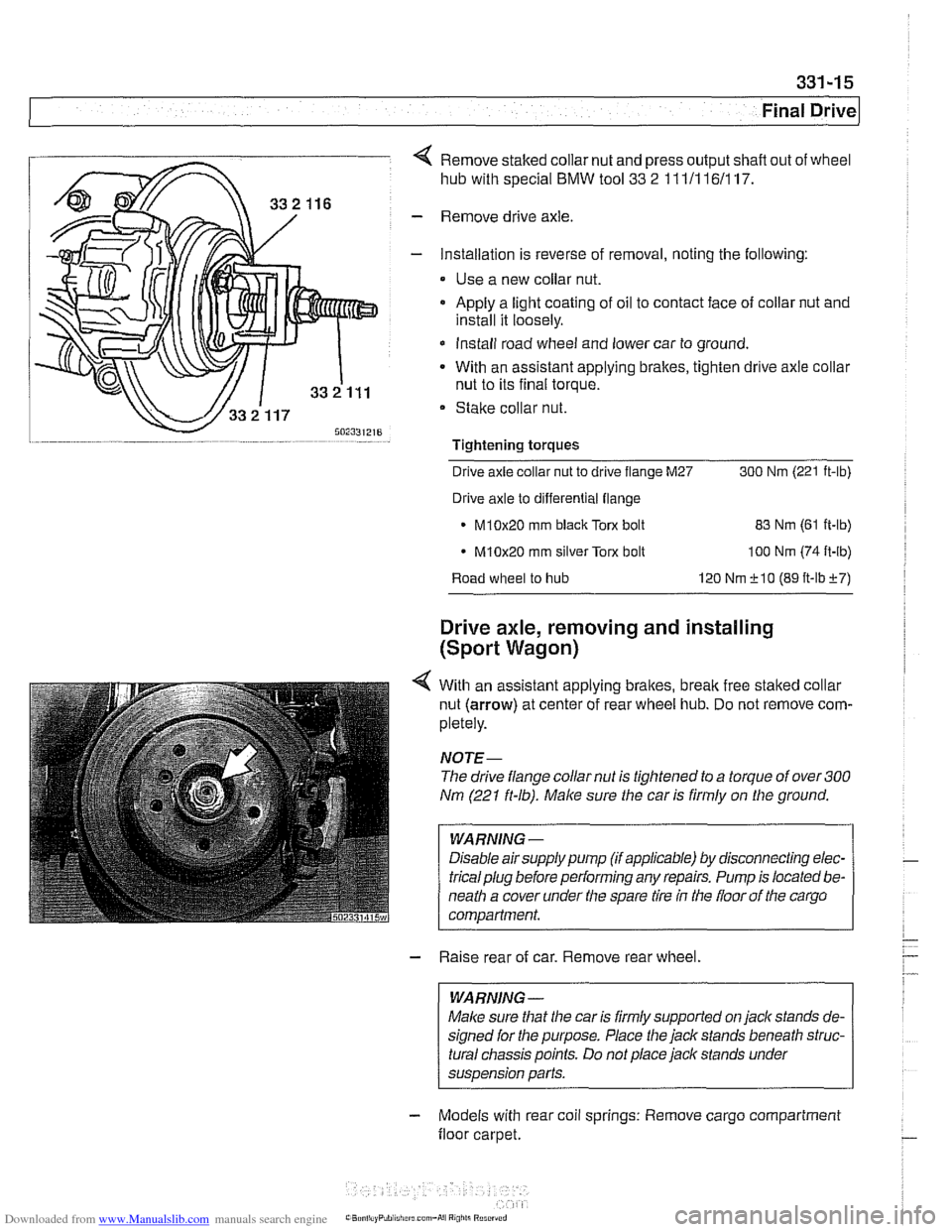
4 Remove staked collar nut and press output shafl out of wheel
hub with special
BMW tool 33 2 111/116/117.
- Remove drive axle.
- Installation is reverse of removal, noting the following:
Use a new collar nut.
a Apply a light coating of oil to contact face of collar nut and
install it loosely.
* Install road wheel and lower car to ground.
- With an assistant applying brakes, tighten drive axle collar
nut to its final torque.
Stake collar nut.
Tightening torques
-
Drive axle collar nut to drive flange M27 300 Nrn (221 ft-lb)
Drive axle to differential flange
* M10x20 rnm black Torx bolt
83 Nrn (61 ft-lb)
M10x20 rnrn silver Torx bolt
100 Nrn (74 ft-lb)
Road wheel to hub 120 Nrn f 10 (89 ft-lbf7)
Drive axle, removing and installing
(Sport Wagon)
4 With an assistant applying brakes, brealc free staked collar
nut (arrow) at center of rear wheel hub. Do not remove com-
pletely.
NOJE-
The drive flange collar nut is tightened to a torque of over 300
Nm (221 ft-lb). Make sure the car is firmly on the ground.
WARNING -
Disable airsupply pump (if applicable) by disconnecting elec-
tricalplug before performing any repairs. Pump is located be-
neath a cover under the spare tire
in the floor of the cargo
compartment.
- Raise rear of car. Remove rear wheel.
WARNING -
Malce sure that the car is firmly supported on jack stands de-
signed for the purpose. Place the jack stands beneath struc-
tural chassis points. Do not place jack stands under
suspension parts.
- Models with rear coil springs: Remove cargo compartment
floor carpet.