bolt BMW 528i 1999 E39 Workshop Manual
[x] Cancel search | Manufacturer: BMW, Model Year: 1999, Model line: 528i, Model: BMW 528i 1999 E39Pages: 1002
Page 675 of 1002
Downloaded from www.Manualslib.com manuals search engine
Steering and Wheel Alignment
Power assist is provided by a belt-driven pump at the lower
left front of the engine. The power steering fluid reservoir is lo-
cated at the left side of the engine compartment.
Power steering pump, removing and
installing
When working with power steering components, absolute
cleanliness is needed to ensure proper operation of the hy-
- Empty power steering fluid reservoir using clean syringe. Do
not reuse fluid.
- Raise front of car. Remove splash shield from under engine.
WARNING-
Make sure the car is firmly supported on jack stands de-
signed for the purpose. Place jack stands beneath structural
chassis points. Do not place jack stands under suspension
Darts.
Remove drive belt from power steering pump. See
020 Main-
tenance.
Remove alternator cooling duct
Remove fluid hoses from pump. Plug openings in pump and
hose ends.
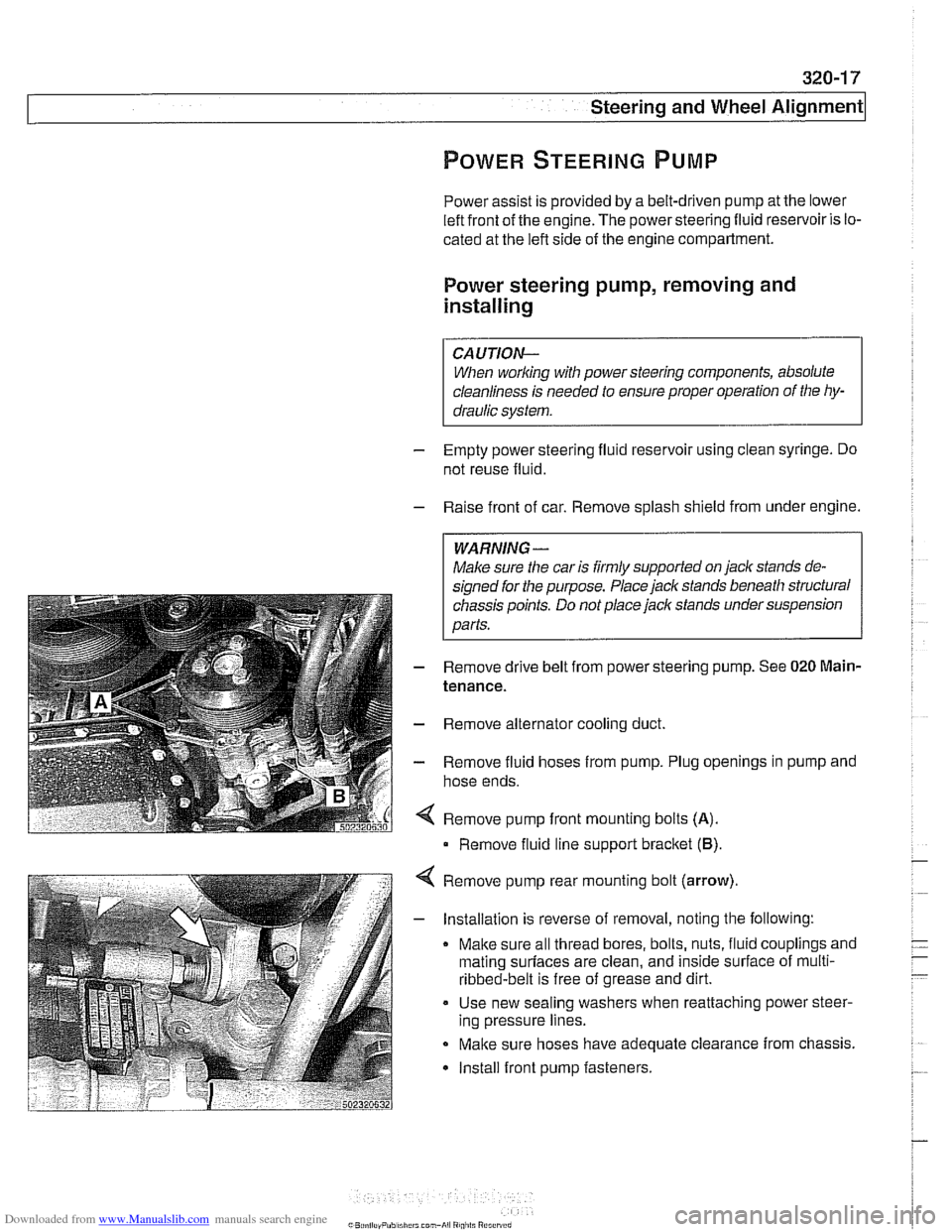
Remove pump front mounting bolts
(A).
Remove fluid line support bracket (B)
Remove pump rear mounting bolt (arrow)
- Installation is reverse of removal, noting the following:
Make sure all thread bores, bolts, nuts, fluid couplings and
mating
surfaces are clean, and inside surface of multi-
ribbed-belt is free of grease and dirt.
Use new sealing washers when reattaching power steer-
ing pressure lines.
Make sure hoses have adequate clearance from chassis.
Install front pump fasteners.
Page 676 of 1002
Downloaded from www.Manualslib.com manuals search engine
-
-steering and wheel -. Alignment I
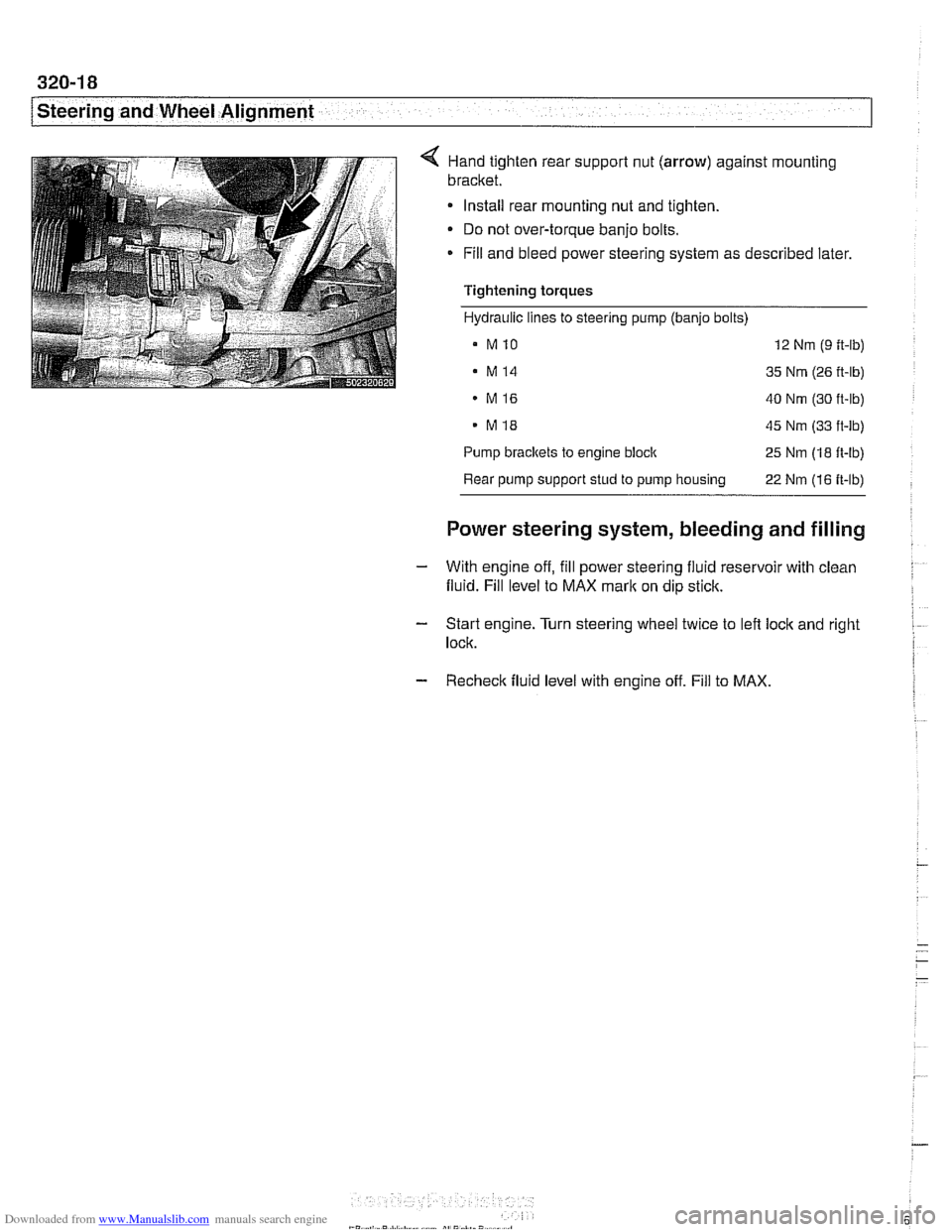
< Hand tighten rear suppoll nut (arrow) against mounting
bracket.
Install rear mounting nut and tighten.
Do not over-torque banjo bolts.
* Fill and bleed power steering system as described later.
Tightening torques
Hydraulic lines to steering pump (banjo bolts)
a MlO 12 Nm (9 ft-lb)
. M14 35 Nm (26 ft-lb)
MI6 40 Nm (30 ft-lb)
. MI8 45 Nm (33 ft-lb)
Pump
brackets to engine block 25 Nm (18 ft-lb)
Rear pump support stud to pump housing
22 Nm (16 ft-lb)
Power steering system, bleeding and filling
- With engine off, fill power steering fluid reservoir with clean
fluid. Fill level to MAX
mark on dip stick.
- Start engine. Turn steering wheel twice to left lock and right I
lock.
- Recheck fluid level with engine off. Fill to MAX.
Page 677 of 1002
Downloaded from www.Manualslib.com manuals search engine
i Steering and Wheel Alignment
RACK AND PINION STEERING
(6-CYLINDER MODELS)
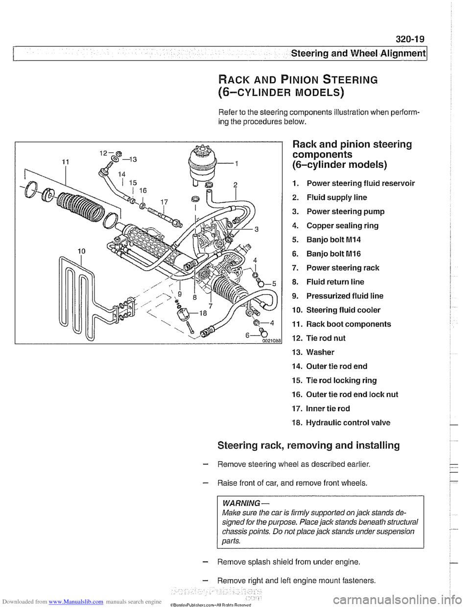
Refer to the steering components illustration when perform-
ing the procedures below.
Rack and pinion steering
components
(6-cylinder models)
1. Power steering fluid reservoir
2. Fluid supply line
3. Power steering pump
4. Copper sealing ring
5. Banjo bolt MI4
6. Banjo bolt MI6
7. Power steering rack
8. Fluid return line
9. Pressurized fluid line
10. Steering fluid cooler
11. Rack boot components
12. Tie rod nut
13. Washer
14. Outer tie rod end
15. Tie rod locking ring
16. Outer tie rod end loclc nut
17. Inner tie rod
18. Hydraulic control valve
Steering rack, removing and installing
- Remove steering wheel as described earlier.
- Raise front of car, and remove front wheels.
WARNING -
Male sure the car is firmly supported on jack stands de-
signed for the purpose. Place jack stands beneath structural
chassis points. Do
not place jack stands under suspension
parts.
- Remove splash shield from under engine.
- Remove right and lefl engine mount fasteners
-" ., - , . ,
Page 678 of 1002
Downloaded from www.Manualslib.com manuals search engine
/steering and Wheel Alignment
Raise engine approximately 40 mm (1.6 in). See 110 Engine
Removal and installation.
Remove right and left engine mounts and remove mount
brackets from subframe.
Empty power steering fluid reservoir using a clean syringe.
Do not reuse power steering fluid.
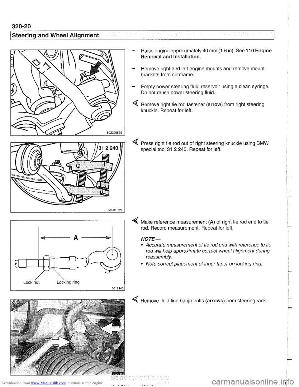
Remove right tie rod fastener (arrow) from right steering
Itnuckle. Repeat for left.
4 Press right tie rod out of right steering knucltle using BMW
special tool 31
2 240. Repeat for left.
/ ~ock nut Loclting ring
0012143
4 Malte reference measurement (A) of right tie rod end to tie
rod. Record measurement. Repeat for left.
NOJE-
0 Accurate measurement of tie rod end with reference to tie
rod will help approximate correct wheel alignment during
reassembly.
Note correct placement of inner taper on
locling ring
Remove fluid line
banjo bolts (arrows)
from steering rack.
Page 679 of 1002
Downloaded from www.Manualslib.com manuals search engine
Steering and Wheel ~lignmentl
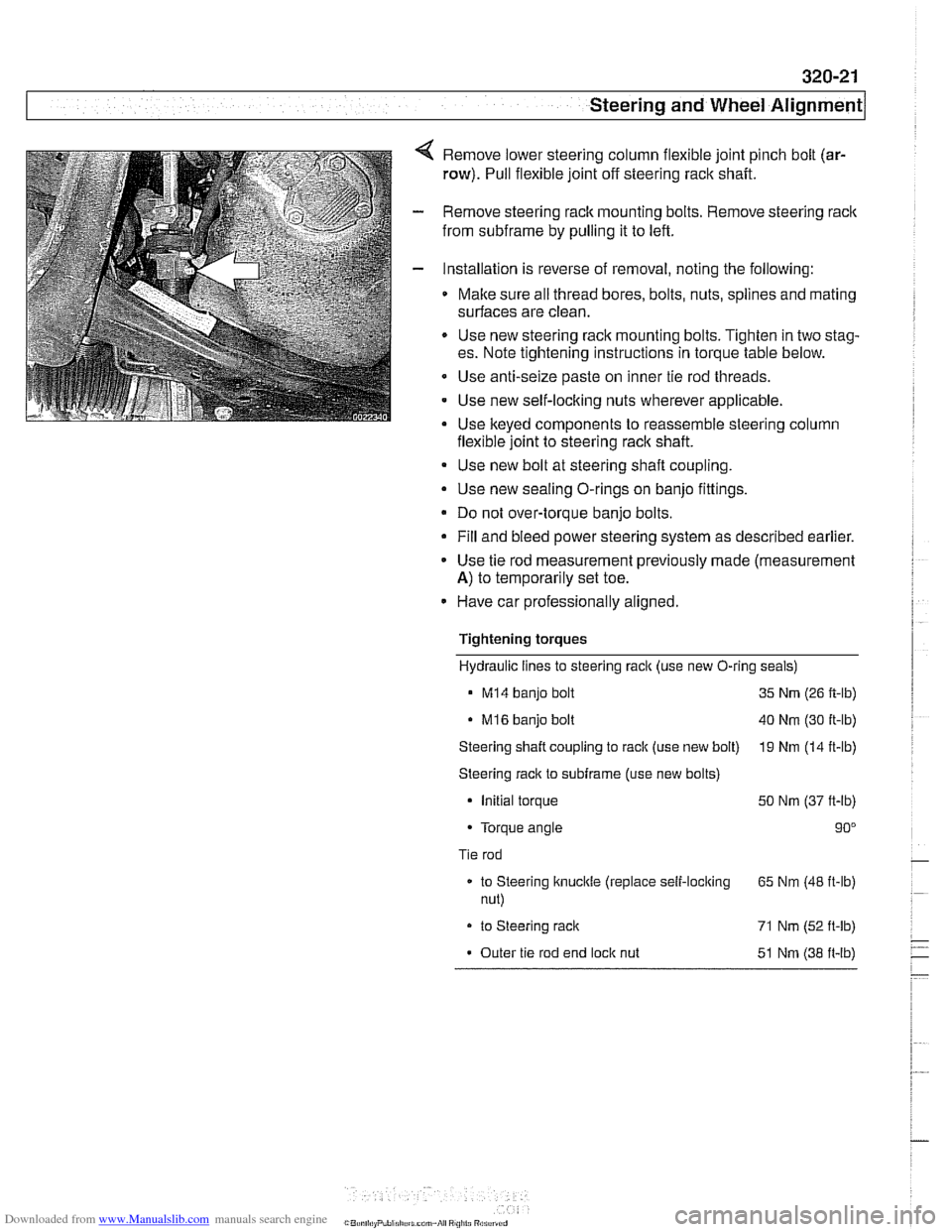
Remove lower steering column flexible joint pinch bolt (ar-
row). Pull flexible joint off steering rack shaft.
Remove steering rack mounting bolts. Remove steering
raclc
from subframe by pulling it to left.
Installation is reverse of removal, noting the following:
Make sure all thread bores, bolts, nuts, splines and mating
surfaces are clean.
Use new steering rack mounting bolts. Tighten in two stag-
es. Note tightening instructions in torque table below.
Use anti-seize paste on inner tie rod threads.
Use new self-loclting nuts wherever applicable.
Use keved
comDonents to reassemble steerino column
flexible\oint to ;teering raclt shaft. u
Use new bolt at steering shaft coupling.
Use new sealing O-rings on banjo fittings.
Do not over-torque banjo bolts.
Fill and bleed power steering system as described earlier.
Use tie rod measurement previously made (measurement
A) to temporarily set toe.
Have car professionally aligned.
Tightening torques Hydraulic lines to steering rack (use new O-ring
seals)
M14 banjo bolt 35 Nrn (26 ft-lb)
. M16 banjo bolt 40 Nm (30 ft-lb)
Steering shaft coupling
to rack (use new bolt) 19 Nm (14 it-lb)
Steering rack to subframe (use new bolts)
- initial torque 50 Nm (37 ft-lb)
Torque angle 90"
Tie rod
to Steering knuckle (replace self-locking
65 Nm (48 ft-lb)
nut)
- to Steering rack 71 Nm (52 ft-ib)
Outer tie rod end lock nut
51 Nm (38 ft-lb)
Page 682 of 1002
Downloaded from www.Manualslib.com manuals search engine
Steering and Wheel Alignment
Tightening torques
Tie rod
to Steering knuckle (replace self-locking nut) 65 Nm (48 it-lb)
to Steering rack 71 Nrn (52 ft-lb)
Outer tie rod end lock nut 51 Nrn (38 ft-lb)
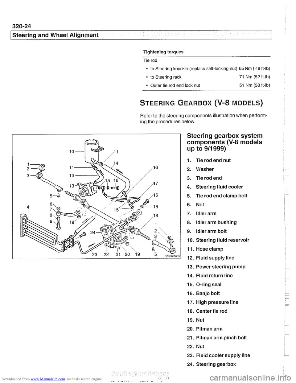
Refer to the steering components illustration when perform-
ing the procedures below.
Steering gearbox system
components
(V-8 models
up to
911 999)
1. Tie rod end nut
2. Washer
3. Tie rod end
4. Steering fluid cooler
5. Tie rod end clamp bolt
6. Nut
7. ldler arm
8. ldler arm bushing
9. ldler arm bolt
10. Steering fluid reservoir
11. Hose clamp
12. Fluid supply line
13. Power steering pump
14. Fluid return line
15. O-ring seal
16. Banjo bolt
17. High pressure line
18. Center tie rod
19. Nut
20. Pitman arm
21.
Pitman arm pinch bolt
22. Nut
23. Fluid cooler supply line
24. Steering gearbox
Page 684 of 1002
Downloaded from www.Manualslib.com manuals search engine
Steering and Wheel Alignment
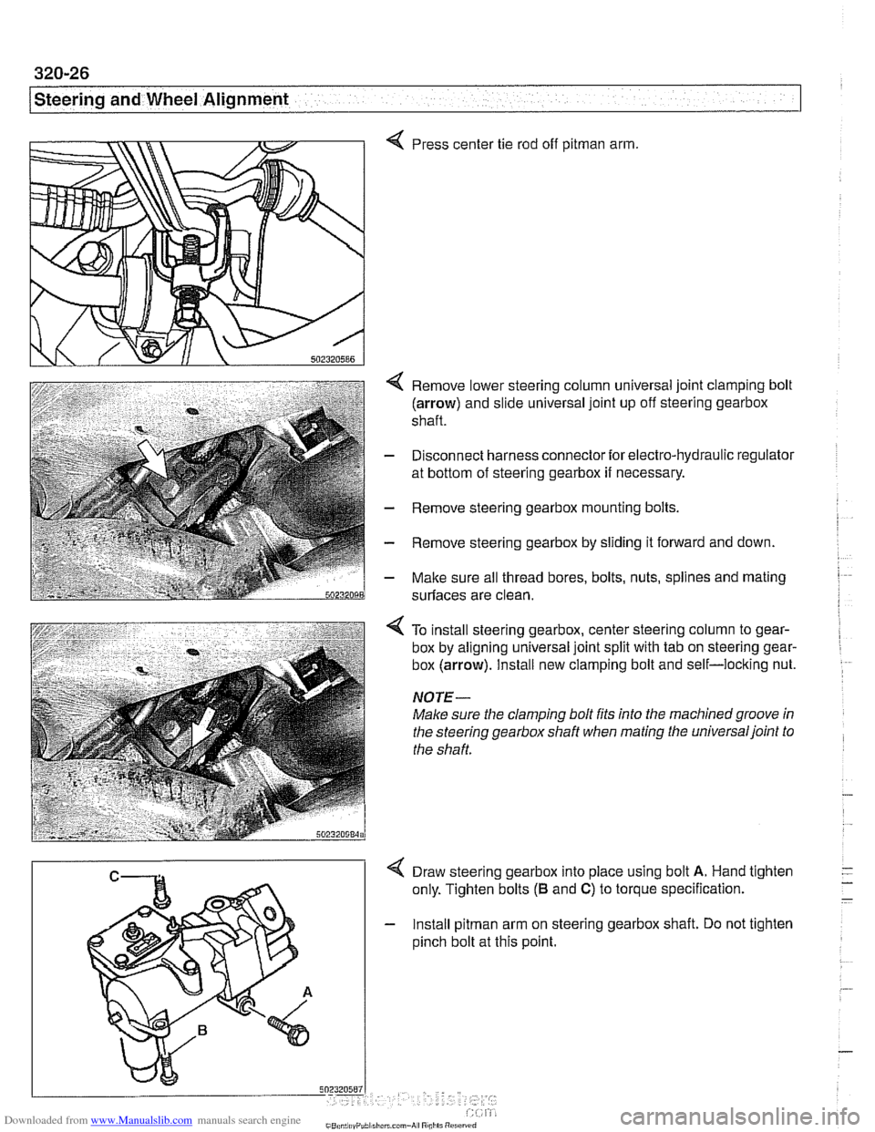
Press center tie rod off pitman arm.
Remove lower steering column universal joint clamping bolt
(arrow) and slide universal joint up off steering gearbox
shaft.
Disconnect harness connector for electro-hydraulic regulator
at bottom of steering gearbox
if necessary.
Remove steering gearbox mounting bolts
Remove steering gearbox by sliding it forward and down.
Malte sure all thread bores, bolts, nuts, splines and mating
surfaces are clean.
4 To install steering gearbox, center steering column to gear-
box by aligning universal joint split with tab on steering gear-
box
(arrow). Install new clamping bolt and self-locking nut.
NOTE-
Make sure the clamping bolt fits into the machinedgroove in
the steering gearbox shaft when mating the universaljoint to
the shaft.
4 Draw steering gearbox into place using bolt A. Hand tighten
only. Tighten bolts
(B and C) to torque specification.
- Install pitman arm on steering gearbox shaft. Do not tighten
pinch bolt at this point.
Page 685 of 1002
Downloaded from www.Manualslib.com manuals search engine
L.. Steering and Wheel ~li~nrnentl ~
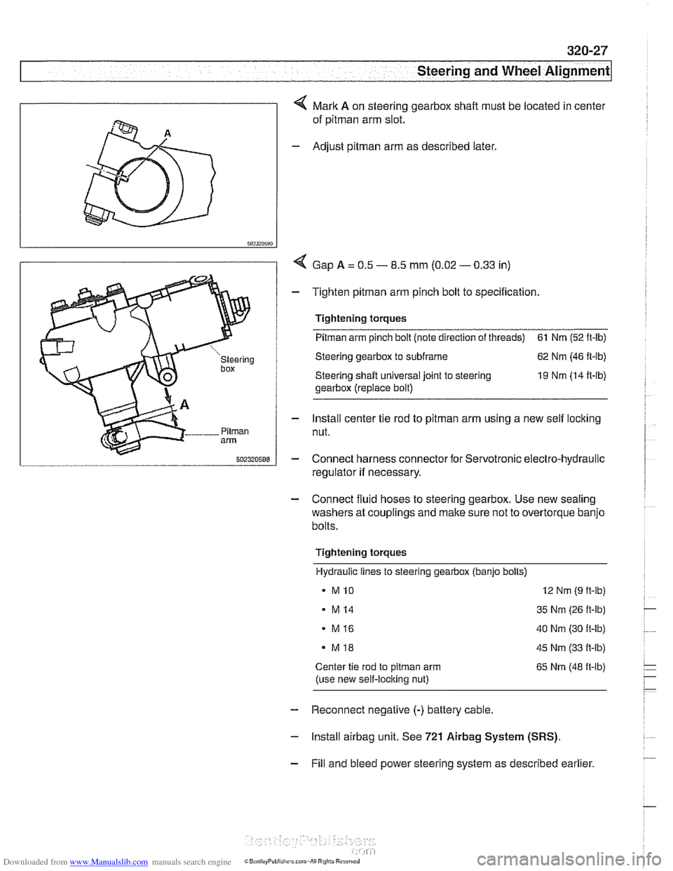
4 Mark A on steering gearbox shaft must be located in center
of
pitman arm slot.
- Adjust pitman arm as described later.
I 5"?~~5~"
I / < Gap A = 0.5 - 8.5 mm (0.02 - 0.33 in)
- Tighten pitman arm pinch bolt to specification.
' 1 Tightening torques
I u "steering Steering gearbox to subframe 62 Nm (46 ft-lb)
box Steering shaft universal joint to steering 19 Nm (14 It-lb)
gearbox (replace bolt)
- Install center tie rod to pitman arm using a new self locking
Pilrnan nut. arm
5nz3zn588 - Connect harness connector for Servotronic electro-hydraulic
regulator
if necessary.
- Connect fluid hoses to steering gearbox. Use new sealing
washers at couplings and make sure not to overtorque banjo
bolts.
Tightening torques Hydraulic lines to steering gearbox (banjo bolts)
MI0 12 Nm (9 ft-lb)
- M14 35 Nm (26 ft-lb)
. M16 40 Nm (30 ft-lb)
MI8 45 Nm (33 it-lb)
Center tie rod to pitrnan arm 65 Nm (48 it-lb)
(use new self-loclting nut)
- Reconnect negative (-) battery cable.
- lnstall airbag unit. See 721 Airbag System (SRS).
- Fill and bleed power steering system as described earlier.
Page 686 of 1002
Downloaded from www.Manualslib.com manuals search engine
320-28
[steering and Wheel Alignment
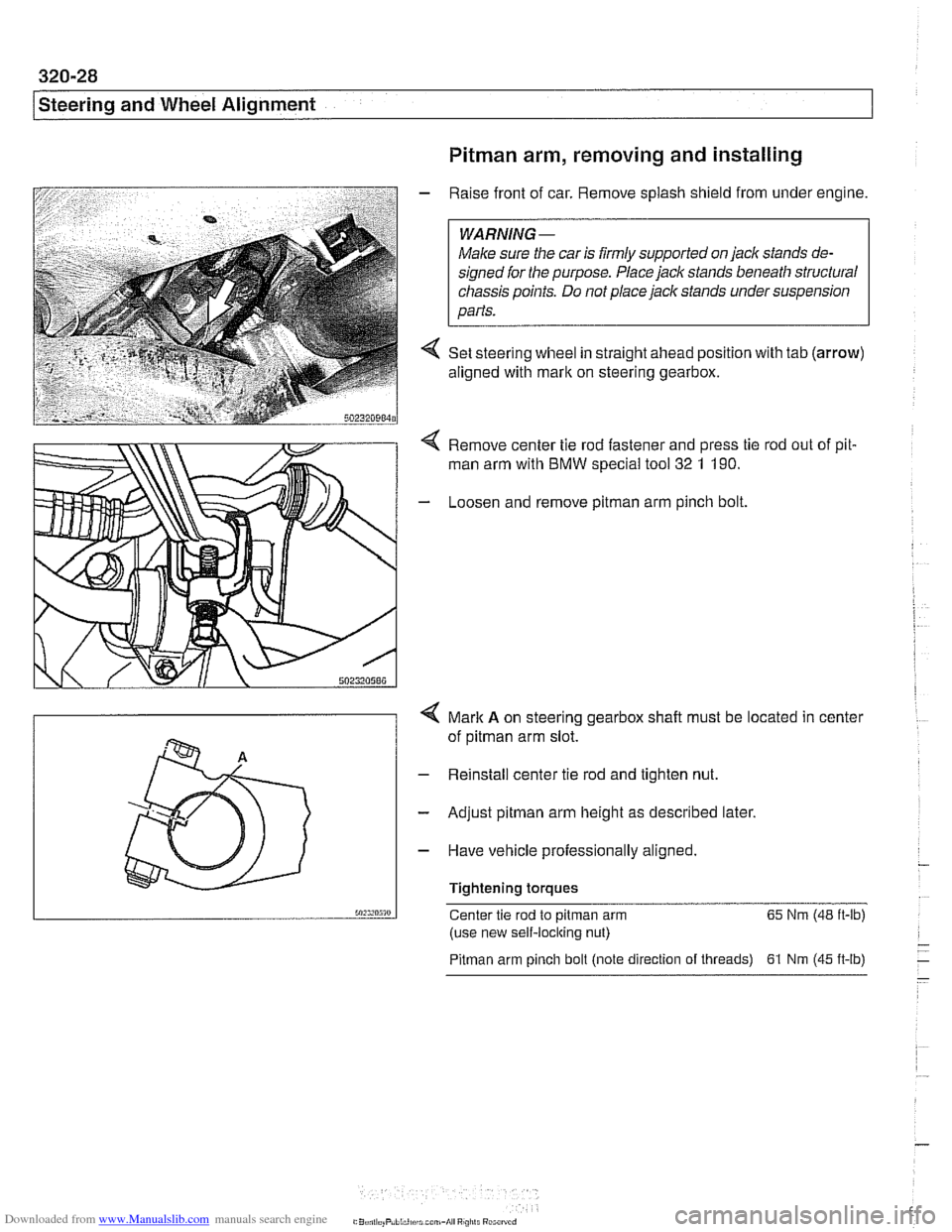
Pitman arm, removing and installing
- Raise front of car. Remove splash shield from under engine.
Male sure the car is
firmly supported on jack stands de-
signed for the purpose. Place jack stands beneath structural
chassis points. Do not place
jaclc stands under suspension
parts.
4 Set steering wheel in straight ahead position with tab (arrow)
aligned with mark on steering gearbox.
Remove center tie rod fastener and press tie rod out of pit.
man arm with BMW special
too1 32 1 190.
- Loosen and remove pitman arm pinch bolt
4 Mark A on steering gearbox shalt must be located in center
of
pitman arm slot.
- Reinstall center tie rod and tighten nut.
- Adjust pitman arm height as described later.
- Have vehicle professionally aligned.
Tightening torques
50:s,n5m Center tie rod to pitman arm 65
Nm (48 ft-lb)
(use new self-locking nut)
Pitman arm pinch bolt (note direction of threads) 61 Nrn (45 ft-lb)
Page 687 of 1002
Downloaded from www.Manualslib.com manuals search engine
Steering and Wheel Alignment
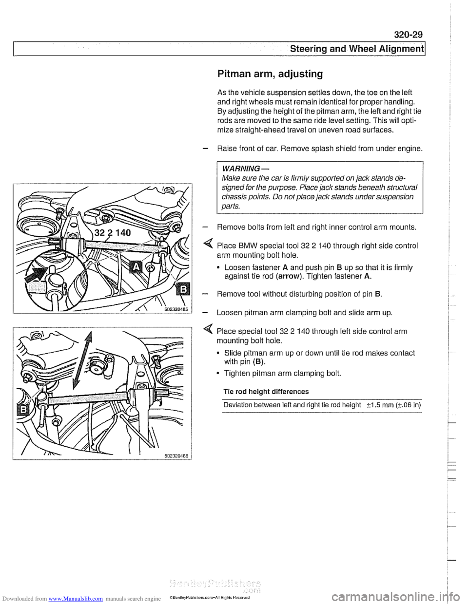
Pitman arm, adjusting
As the vehicle suspension settles down, the toe on the left
and right wheels must remain identical for proper handling.
By adjusting the height of the
pitman arm, the left and right tie
rods are moved to the same ride level setting. This will opti-
mize straight-ahead travel on uneven road surfaces.
- Raise front of car. Remove splash shield from under engine.
WARNING-
Male sure the car is iirmly supported on jack stands de-
signed ior the purpose. Place jack stands beneath structural
chassis points. Do not place
jaclc stands under suspension
parts.
- Remove bolts from left and right inner control arm mounts.
Place
BMW special tool 32 2 140 through right side control
arm mounting bolt hole.
Loosen fastener
A and push pin El up so that it is firmly
against tie rod
(arrow). Tighten fastener A.
- Remove tool without disturbing position of pin El.
- Loosen pitman arm clamping bolt and slide arm up.
4 Place special tool 32 2 140 through left side control arm
mounting bolt hole.
Slide
pitman arm up or down until tie rod makes contact
with pin
(El).
Tighten pitman arm clamping bolt.
Tie rod height differences
Deviation between
left and right tie rod height -?-I .5 rnrn (LO6 in)