bolt BMW 528i 1999 E39 Owner's Guide
[x] Cancel search | Manufacturer: BMW, Model Year: 1999, Model line: 528i, Model: BMW 528i 1999 E39Pages: 1002
Page 121 of 1002
Downloaded from www.Manualslib.com manuals search engine
11 3-27
Cylinder Head Removal and Installation
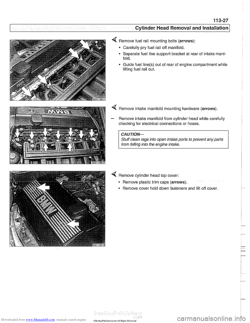
< Remove fuel rail mounting bolts (arrows):
- Carefully pry fuel rail off manifold.
Separate fuel line support bracket at rear of intake mani-
fold.
Guide fuel
line(s) out of rear of engine compartment while
lifting fuel rail out.
4 Remove intake manifold mountino hardware (arrows).
I from falling into the engine intake. I
4 Remove cylinder head top cover:
- Remove plastic trim caps (arrows).
Remove cover hold down fasteners and
lilt off cover.
Page 122 of 1002
Downloaded from www.Manualslib.com manuals search engine
I Cylinder Head Removal and Installation
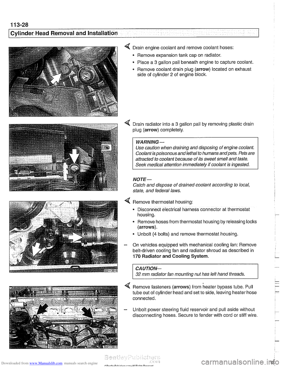
4 Drain engine coolant and remove coolant hoses:
Remove expansion tank cap on radiator.
Place a
3 gallon pail beneath engine to capture coolant
Remove coolant drain plug (arrow) located on exhaust
side of cylinder
2 of engine block.
4 Drain radiator into a 3 gallon pail by removing plastic drain
plug (arrow) completely.
Use caution when draining and disposing of engine coolant.
Coolant is poisonous andlethal to humans andpets. Pets are
attracted to coolant because of its sweet smell and taste.
Seek medical
attention immediately if coolant is ingested.
NOTE-
Catch and dispose of drained coolant according to local,
state, and federal laws.
4 Remove thermostat housing:
. Disconnect electrical harness connector at thermostat
housing.
. Remove hoses from thermostat hous~ng by releasing loclts
(arrows).
Unbolt
(4 bolts) and remove thermostat hous~ng.
- On vehicles equipped with mechanical cooling fan: Remove
belt-driven cooling fan and radiator shroud as described in
170 Radiator and Cooling System.
CAUTIOI\C
32 mm radiator fan mounting nut has left hand threads. r
4 Remove fasteners (arrows) from heater bypass tube. Pull
tube out of cylinder head and set to side, leaving heater hose
connected.
- Unbolt power steering fluid reservoir and pull aside without
disconnecting hoses. Secure to fender with cord or stiff wire.
Page 123 of 1002
Downloaded from www.Manualslib.com manuals search engine
Cylinder Head Removal and Installation
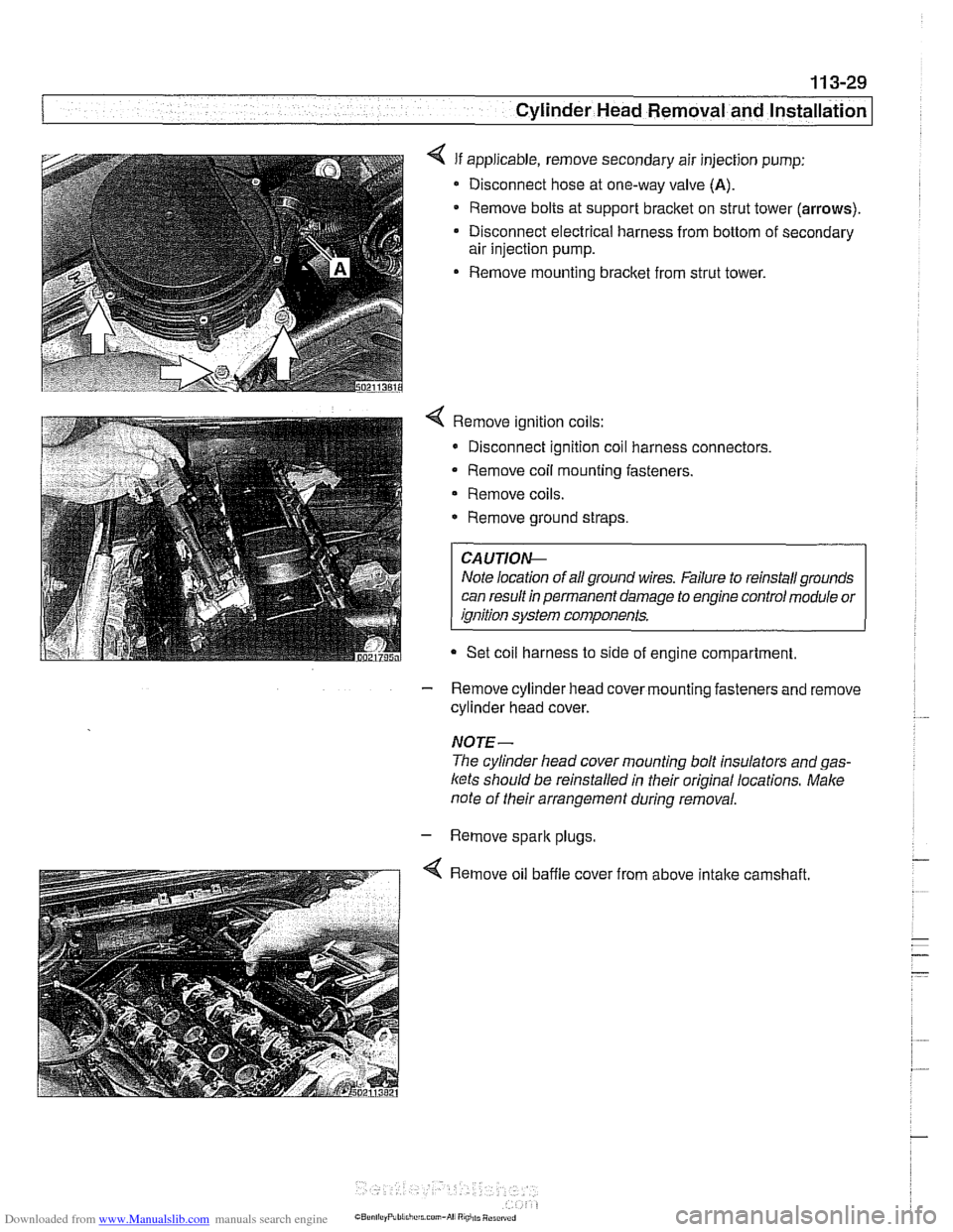
4 If applicable, remove secondary air injection pump:
Disconnect hose at one-way valve
(A).
Remove bolts at support bracket on strut tower (arrows).
Disconnect electrical harness from bottom of secondary
air injection pump.
Remove mounting bracket from strut tower.
4 Remove ignition coils:
* Disconnect ignition coil harness connectors.
Remove coil mounting fasteners.
Remove coils.
* Remove ground straps.
CA UTIOI\C
Note location of all ground wires. Failure to reinstall grounds
can result in permanent damage to engine control module or
ignition system components.
Set coil harness to side of engine compartment
- Remove cylinder head cover mounting fasteners and remove
cylinder head cover.
NOTE-
The cylinder head cover mounting bolt insulators and gas-
ltets should be reinstalled in their original locations. Male
note of their arrangement during removal.
- Remove spark plugs
4 Remove oil baffle cover from above intake camshaft.
Page 124 of 1002
Downloaded from www.Manualslib.com manuals search engine
Cylinder Head Removal and installation - - .- - - - -
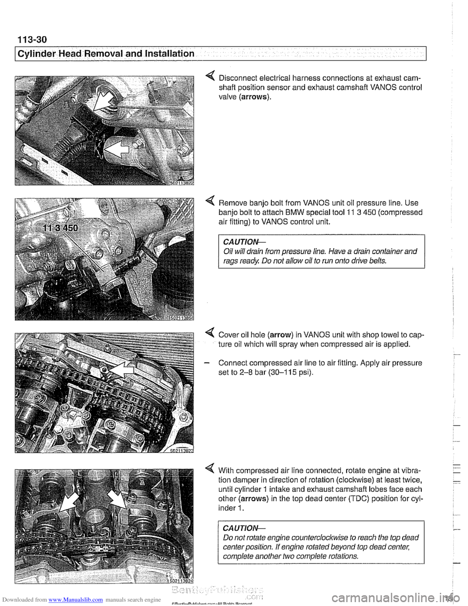
4 Disconnect electrical harness connections at exhaust cam-
shaft position sensor and exhaust camshaft VANOS control
valve (arrows).
4 Remove banjo bolt from VANOS unit oil pressure line. Use
banjo bolt to attach
BMW special tool 11 3 450 (compressed
air fitting) to VANOS control unit.
CAUTIOI\C
Oil will drain from pressure line. Have a drain container and
rags ready Do not allow oil to run onto drive belts.
4 Cover oil hole (arrow) in VANOS unit with shop towel to cap-
ture oil which will spray when compressed air is applied.
- Connect compressed air line to air fitting. Apply air pressure
set to
2-8 bar (30-1 15 psi).
4 With compressed air line connected, rotate engine at vibra-
tion damper in direction of rotation (clockwise) at least twice,
until cylinder 1 intake and exhaust camshaft lobes face each
other (arrows) in the top dead center (TDC) position for cyl-
inder
1.
CAUTION--
Do not rotate engine counterclocltwise to reach the top dead
center position. If engine rotated beyond top dead center;
complete another two complete rotations.
Page 129 of 1002
![BMW 528i 1999 E39 Owners Guide Downloaded from www.Manualslib.com manuals search engine
11 3-35
- cylinder Head Removal and Installation] -
< Lift off exhaust and intake sprocltets together with secondary
chain, thrust spac](/img/1/2822/w960_2822-128.png "BMW 528i 1999 E39 Owners Guide Downloaded from www.Manualslib.com manuals search engine
11 3-35
- cylinder Head Removal and Installation] -
< Lift off exhaust and intake sprocltets together with secondary
chain, thrust spac")
Downloaded from www.Manualslib.com manuals search engine
11 3-35
- cylinder Head Removal and Installation] -
< Lift off exhaust and intake sprocltets together with secondary
chain, thrust spacer
(A), and splined shafl (B).
CAUTION-
Splined shafts share the same part number for both intake
and exhaust camshafts. Used splined shafts must be
rein-
stalled in their original positions.
Remove exhaust camshaft splined sleeve
(A) and shaft (B).
Remove secondary chain tensloner mounting bolts (arrows)
and remove tensioner with retaining pin in place.
Page 131 of 1002
Downloaded from www.Manualslib.com manuals search engine
Cylinder Head Removal and Installation I
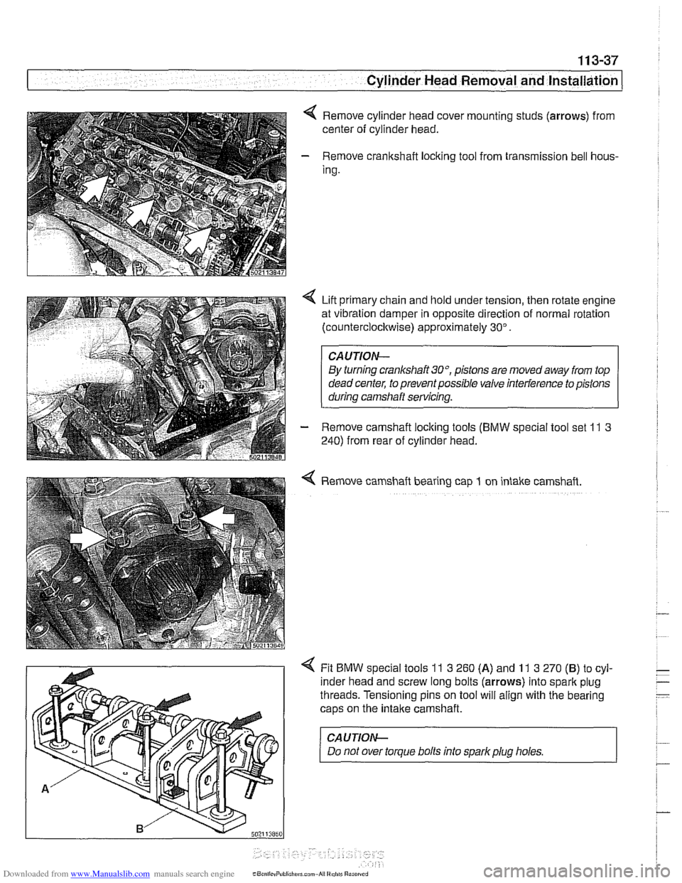
Remove cylinder head cover mounting studs (arrows) from
center of cylinder head.
- Remove crankshaft loclting tool from transmission bell hous-
Ing.
Lift primary chain and hold under tension, then rotate engine
at vibration damper in opposite direction of normal rotation
(counterclocltwise) approximately 30".
CAUTION-
By turning crankshait3O0, pistons are movedaway from top
dead center, to prevent possible valve interference to pistons
during camshaft servicing.
- Remove camshaft loclting tools (BMW special tool set 11 3
240) from rear of cylinder head.
4 Remove camshaft bearing cap 1 on intake camshaft.
4 Fit BMW special tools 11 3 260 (A) and 11 3 270 (B) to cyl-
inder head and screw long bolts (arrows) into spark plug
threads. Tensioning pins on tool will align with the bearing
caps on the
intake camshaft.
CAUJION-
Do not over torque bolts into sparkplug holes.
Page 132 of 1002
Downloaded from www.Manualslib.com manuals search engine
11 3-38
I Cylinder Head Removal and Installation
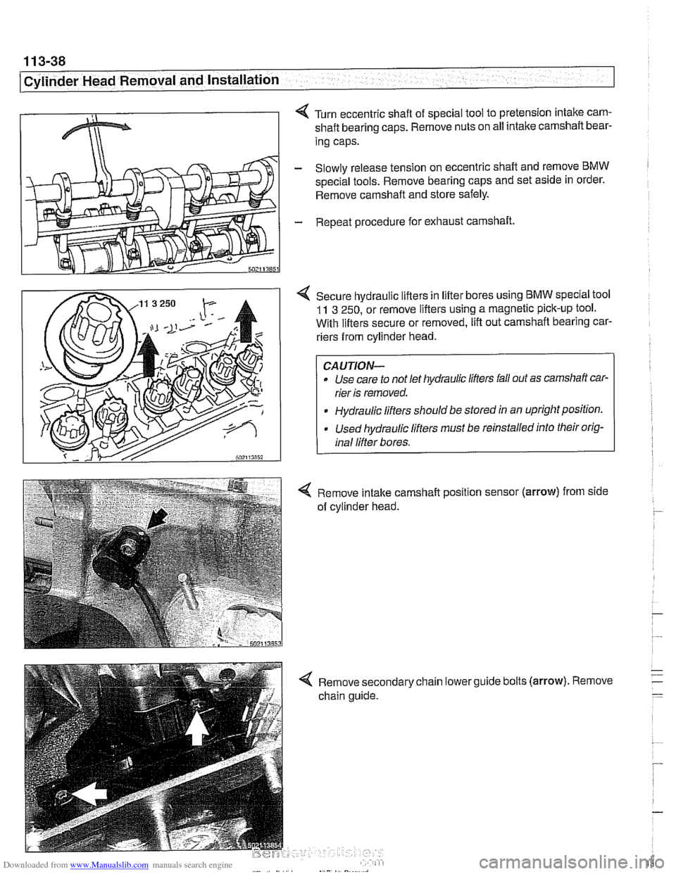
< Turn eccentric shaft of special tool to pretension intake cam-
shaft bearing caps. Remove nuts on all intake camshaft bear-
ing caps.
- Slowly release tension on eccentric shaft and remove BMW
spec~al tools. Remove bearing caps and set as~de in order.
Remove camshaft and store safely.
- Repeat procedure for exhaust camshaft.
4 Secure hydraulic lifters in lifter bores using BMW speclal tool
11 3 250, or remove lifters using a magnetic pick-up tool.
With lifters secure or removed, lift out camshaft bearing car-
riers from cylinder head.
Use care to not let hydraulic lifters fall out as camshaft car-
rier is removed.
Hydraulic lifters should be stored
ln an uprightpositlon.
Used hydraulic lifters must be reinstalled into their orig-
inal lifter bores.
4 Remove intake camshaft position sensor (arrow) from side
of cylinder head.
4 Remove secondary chain lowerguide bolts (arrow). Remove
chain guide.
Page 133 of 1002
Downloaded from www.Manualslib.com manuals search engine
. - -- -
Cylinder Head Removal and Installation --
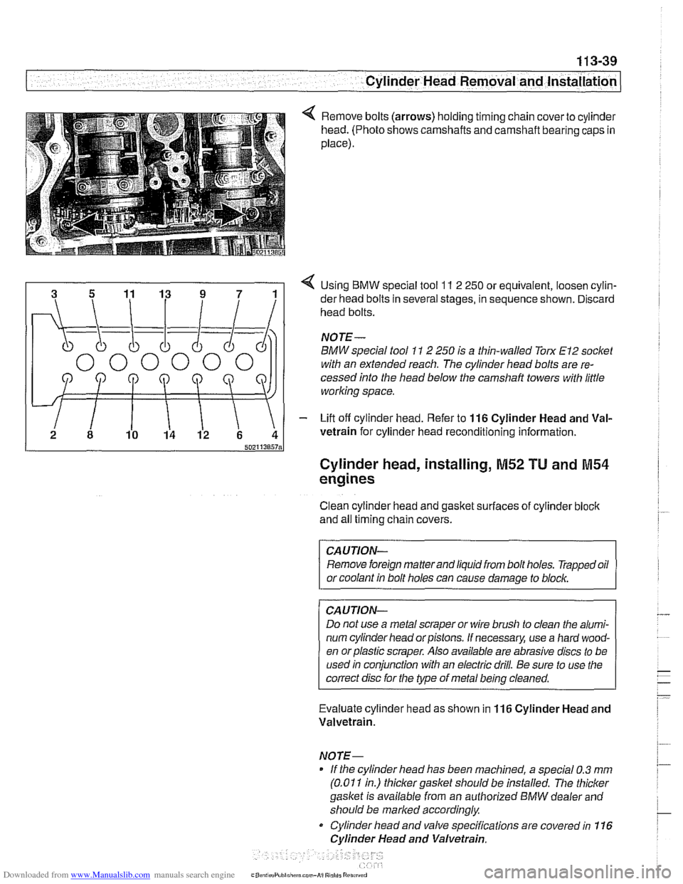
Remove bolts (arrows) holding timing chain cover to cylinder
head. (Photo shows camshafts and camshaft bearing caps in
place).
4 Using BMW special tool 11 2 250 or equivalent, loosen cylin-
der head bolts in several stages, in sequence shown. Discard
head bolts.
NOJE-
BMW special tool 11 2 250 is a thin-walled Torx El2 socket
with an extended reach. The cylinder head bolts are re-
cessed into the head below the
camshaft towers with little
working space.
- Lift off cylinder head. Refer to 116 Cylinder Head and Val-
vetrain for cylinder head reconditioning information.
Cylinder head, installing, M52 TU and M54
engines
Clean cylinder head and gasket surfaces of cylinder bloclc
and all timing chain covers.
CAUTION- Remove foreign matter and liquid from bolt holes. Trapped oil
or coolant in bolt holes can cause damage to
blocl~,
CAUJION-
Do not use a metal scraper or wire brush to clean the alumi-
num cylinder head or pistons. If necessary, use a hard wood-
en orplastic scraper. Also available are abrasive discs to be
used in conjunction with an electric drill. Be sure to use the
correct disc for the type of metal being cleaned.
Evaluate cylinder head as shown in
116 Cylinder Head and
Valvetrain.
NOTE- If the cylinder head has been machined, a special 0.3
mm
(0.01 1 in.) thicker gasket should be installed. The thicker
gasket is available from an authorized
BMW dealer and
should be marked accordingly
Cylinder head and valve specifications are covered in 116
Cylinder Head and Valvetrain.
Page 134 of 1002
Downloaded from www.Manualslib.com manuals search engine
11 3-40
I Cylinder Head Removal and Installation
Lubricate camshafts, camshaft carriers, bearing caps, hy-
draulic lifters, friction washers, splined shafts and spline hubs
with assembly lubricant before installation.
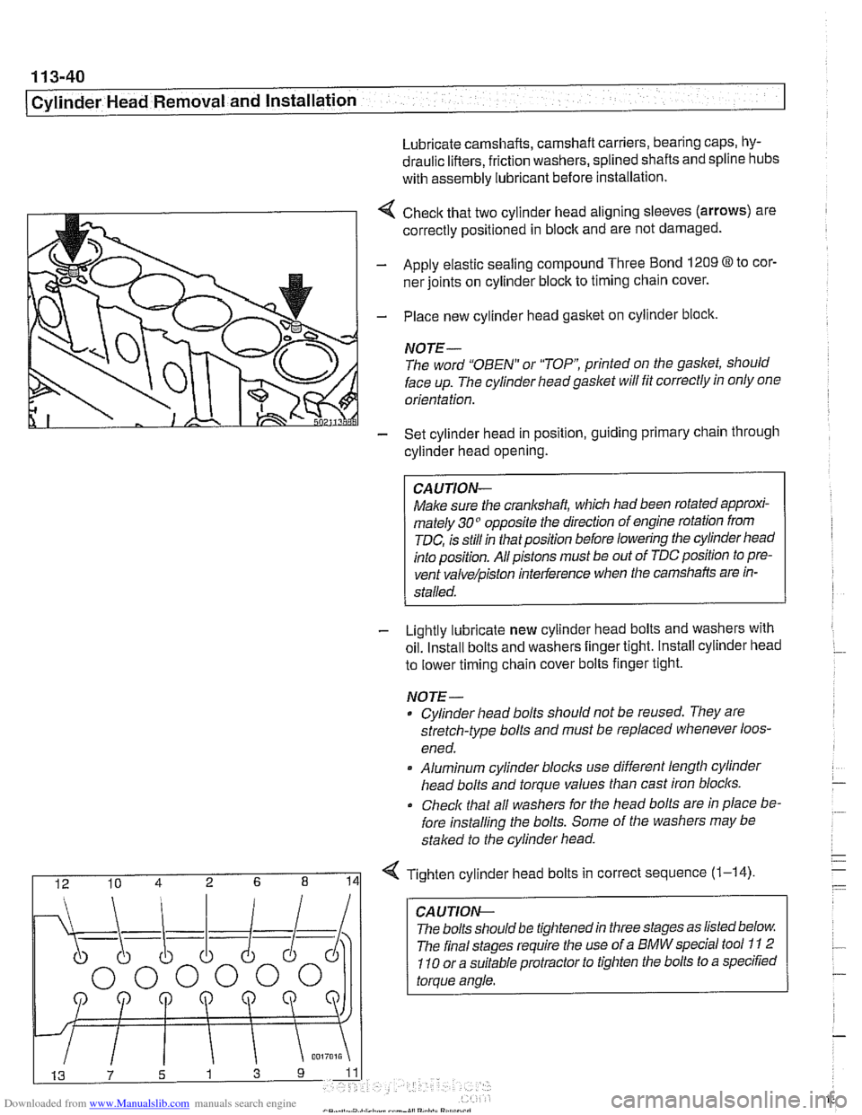
4 Check that two cylinder head aligning sleeves (arrows) are
correctly positioned in block and are not damaged.
- Apply elastic sealing compound Three Bond 1209 8 to cor-
ner joints on cylinder block to timing chain cover.
- Place new cylinder head gasket on cylinder block.
NOTE-
The word "OBEN" or "TOP printed on the gasket, should
face up. The cylinder headgaslet will fit correctly in only one
orientation.
- Set cylinder head in position, guiding primary chain through
cylinder head opening.
CAUJION-
Make sure the crankshaft, which had been rotated approxi-
mately 30" opposite the direction of engine rotation from
TDC, is still in thatposition before lowering the cylinder head
into position. All pistons must be out of TDC position to pre-
vent
valve/piston interference when the camshafts are in-
stalled.
- Lightly lubricate new cylinder head bolts and washers with
oil. Install bolts and washers finger tight. Install cylinder head
to lower timing chain cover bolts finger tight.
NOJE-
Cylinder head bolts should not be reused. They are
stretch-type bolts and must be replaced whenever loos-
ened.
* Aluminum cylinder blocls use different length cylinder
head bolts and torque values than cast iron blocks.
Check that all washers for
Nle head bolts are in place be-
fore installing the bolts. Some of the washers may be
staked to the cylinder head.
I 12 10 4 2 6 8 141 Tighten cylinder head bolts in correct sequence (1-14)
CA U TIOW-
The bolts should be tightened in three stages as listed below
The final stages require the use of a BMW special tool
11 2
110 or a suitable protractor to tighten the bolts to a specified
torque angle.
Page 135 of 1002
![BMW 528i 1999 E39 Owners Guide Downloaded from www.Manualslib.com manuals search engine
. - ..
Cylinder Head Removal and installation] --
- Secure cylinder head bolts by torquing an additional 90"
each for Stage 2 and 3.
T](/img/1/2822/w960_2822-134.png "BMW 528i 1999 E39 Owners Guide Downloaded from www.Manualslib.com manuals search engine
. - ..
Cylinder Head Removal and installation] --
- Secure cylinder head bolts by torquing an additional 90\"
each for Stage 2 and 3.
T")
Downloaded from www.Manualslib.com manuals search engine
. - ..
Cylinder Head Removal and installation] --
- Secure cylinder head bolts by torquing an additional 90"
each for Stage 2 and 3.
Tightening torques
Cylinder head to engine block
(aluminum block)
Stage
1 40 Nm (30 it-lb)
Stage 2 +90°
Stage 3 80'
4 lnstall intake camshaft position sensor (arrow).
4 Install lower secondary chain guide. Tighten tom bolts to
specifications. The bolt on the intake camshaft side is long
and extends into the engine block.
4 Install and tighten cylinder head-to-lower timing chain cover
bolts (arrows). (Photo shows camshafts in place).
Tightening torque Secondary chain guide to cylinder head
10 Nm (89 in-lb)
Cylinder head to lower timing chain cover
M6 10 Nm (89 in-lb)
M7 15 Nm (1 1 it-lb)