bolt BMW 528i 1999 E39 Manual PDF
[x] Cancel search | Manufacturer: BMW, Model Year: 1999, Model line: 528i, Model: BMW 528i 1999 E39Pages: 1002
Page 221 of 1002
Downloaded from www.Manualslib.com manuals search engine
Cylinder Head and valvetrain1
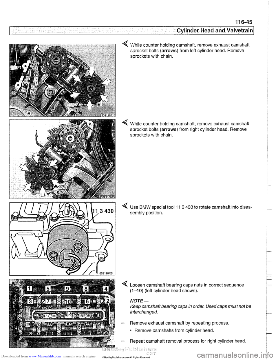
While counter holding camshaft, remove exhaust camshaft
sprocket bolts
(arrows) from left cylinder head. Remove
sprocltets with chain.
< While counter holding camshaft, remove exhaust camshaft
sprocket bolts
(arrows) from right cylinder head. Remove
sprocltets with chain.
4 Use BMW special tool 11 3 430 to rotate camshaft into disas-
sembly position.
4 Loosen camshaft bearing caps nuts in correct sequence
(1-10) (left cylinder head shown).
NOTE -
Keep camshaft bearing caps in order. Used caps must not be
interchanged.
- Remove exhaust camshaft by repeating process.
0 Remove camshafts from cylinder head.
- Repeat camshaft removal process for right cylinder head.
Page 227 of 1002
Downloaded from www.Manualslib.com manuals search engine
- -.
Cylinder Head and valvetrain1
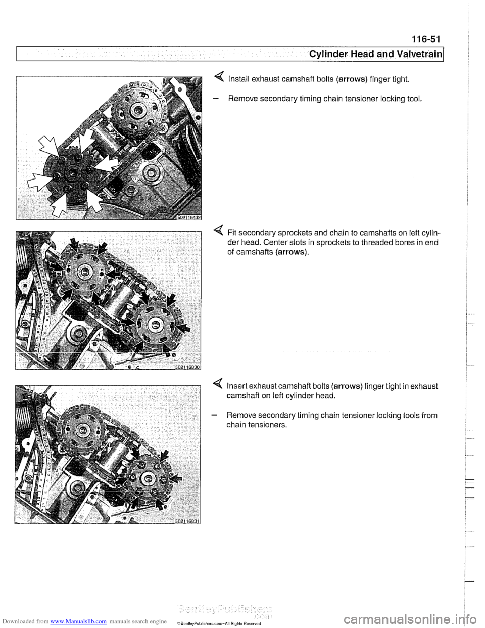
Install exhaust camshaft bolts (arrows) finger tight.
Remove secondary timing chain tensioner
loclting tool.
< Fit secondary sprockets and chain to camshafts on left cylin-
der head. Center slots in sprocltets to threaded bores in end
of camshafts
(arrows).
Insert exhaust camshaft bolts (arrows) finger tight in exhaust
camshaft on left cylinder head.
Remove secondary timing chain tensioner locking tools from
chain tensioners.
Page 228 of 1002
Downloaded from www.Manualslib.com manuals search engine
ICylinder Head and Valvetrain -.
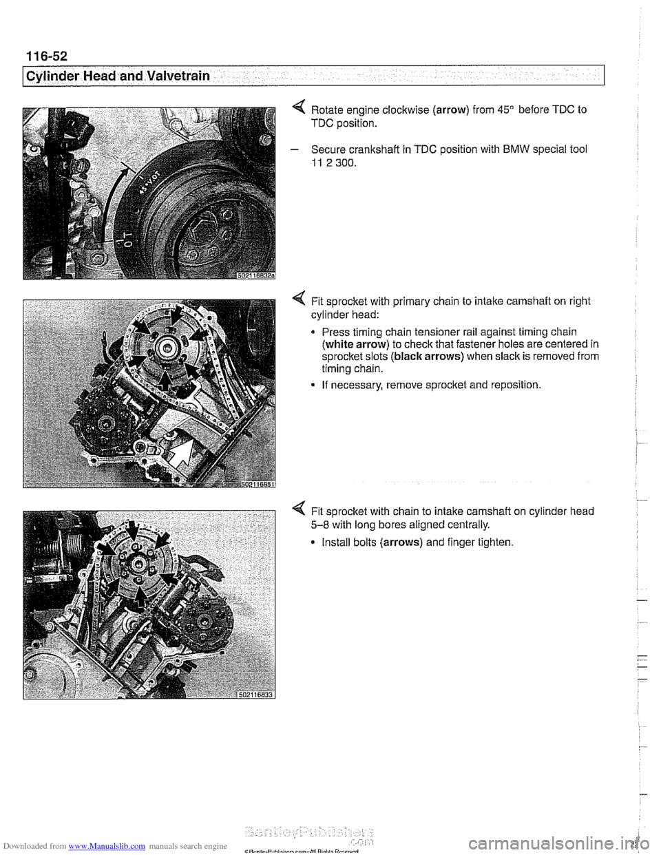
Rotate engine clockwise (arrow) from 45" before TDC to
TDC position.
Secure crankshaft in
TDC position with BMW special tool
11 2 300.
4 Fit sprocket with primary chain to intaite camshaft on right
cylinder head:
Press timing chain tensioner rail against timing chain
(white arrow) to check that fastener holes are centered in
sprocket slots (black arrows) when slack is removed from
timing chain.
If necessary, remove sprocket and reposition.
Fit sprocket with chain to intake camshaft
5-8 with long bores aligned centrally.
Install bolts (arrows) and finger tighten cylinder
head
Page 229 of 1002
Downloaded from www.Manualslib.com manuals search engine
Cylinder Head and valvetrain'
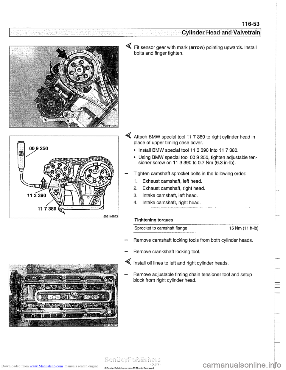
Fit sensor gear with mark (arrow) pointing upwards. Install
bolts and finger tighten.
4 Attach BMW special tool 11 7 380 to right cylinder head in
place of upper timing case cover.
Install BMW special tool
11 3 390 into 11 7 380.
Using BMW special tool 00 9 250, tighten adjustable ten-
sioner screw on
11 3 390 to 0.7 Nm (6.3 in-lb).
- T~ghten camshaft sprocket bolts in the following order:
1. Exhaust camshaft, left head.
2. Exhaust camshaft, right head.
3. Intake camshaft, left head.
4. Intake camshaft, right head.
Tightening torques Sprocket
to camshaft flange 15 Nm (I 1 ft-lb)
- Remove camshaft locking tools from both cylinder heads.
- Remove crankshaft locking tool.
4 lnstall oil lines to left and right cylinder heads.
- Remove adjustable timing chain tensioner tool and setup
block from right cylinder head.
Page 230 of 1002
Downloaded from www.Manualslib.com manuals search engine
11 6-54
Cylinder Head and Valvetrain
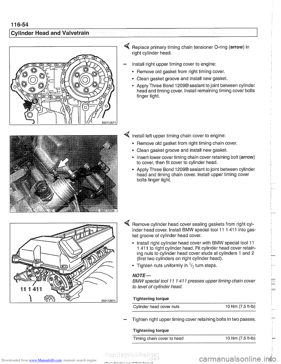
Replace primary timing chain tensioner O-ring (arrow) in
right cylinder head.
- lnstall right upper timing cover to engine:
Remove old gasket from right timing cover.
Clean gasket groove and install new gasket.
Apply Three Bond
12098sealant to joint between cylinder
head and timing cover. Install remaining timing cover bolts
finger tight.
lnstall left upper timing chain cover to engine:
Remove old gasket from right timing chain cover.
Clean gasket groove and install new gasket.
Insert lower cover timing chain cover retaining bolt (arrow)
to cover, then fit cover to cylinder head.
Apply Three Bond 12098 sealant to joint between cylinder
head and timing chain cover. lnstall upper timing cover
bolts finger tight.
4 Remove cylinder head cover sealing gaskets from right cyl-
inder head cover. lnstall BMW special tool 11
1 41 1 into gas-
ket groove of cylinder head cover.
lnstall right cylinder head cover with BMW special tool
11
1 41 1 to right cylinder head. Fit cylinder head cover retain-
ing nuts to cylinder head cover studs at cylinders
1 and 2
(first two cylinders on right cylinder head).
Tighten nuts uniformly in
'I2 turn steps.
NOTE-
BMW special tool 11 1 41 1 presses upper timing chain cover
to level of cylinder head.
Tightening torque Cylinder head cover nuts
10 Nm (7.5 n-lb)
- Tighten right upper timing cover retaining bolts in two passes.
Tightening torque
Timing chain cover to head
10 Nm (7.5 ft-lb)
Page 231 of 1002
Downloaded from www.Manualslib.com manuals search engine
11 6-55
Cvlinder Head and valvetrain1
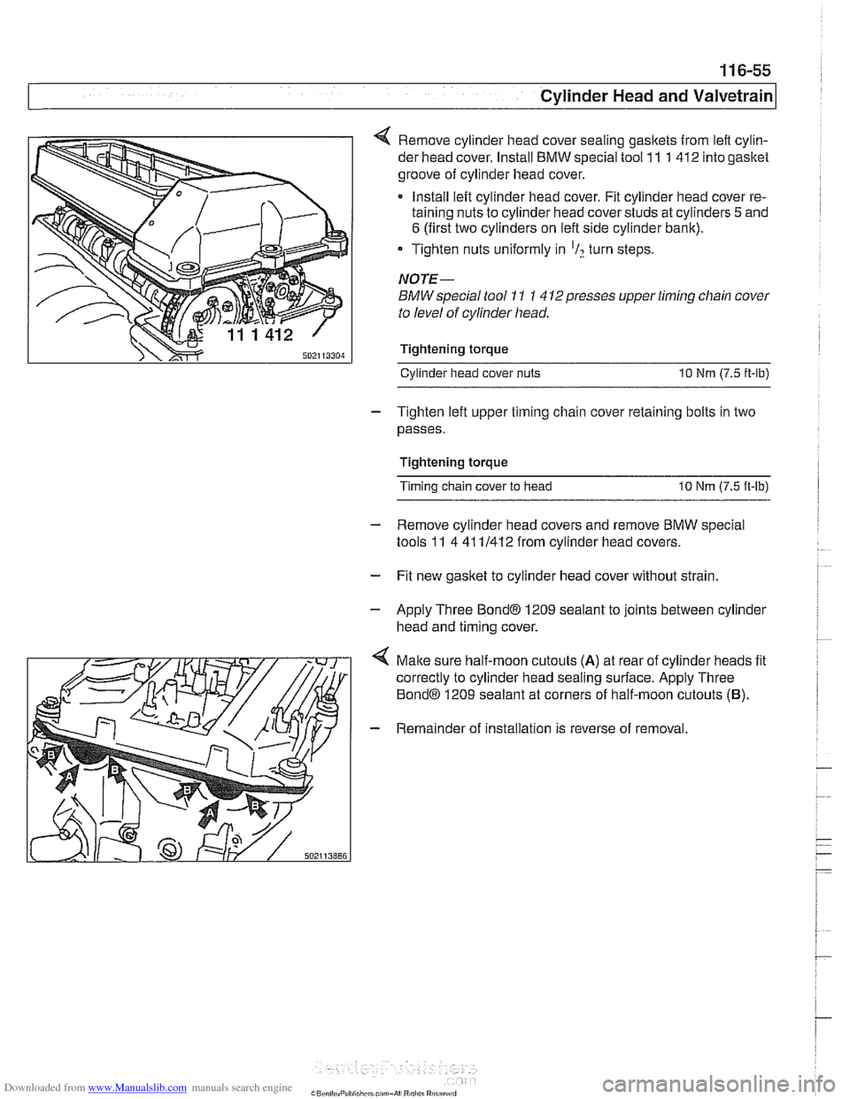
4 Remove cylinder head cover sealing gasltets from left cylin-
der head cover. Install BMW special tool 11 1 412 into gasket
groove of cylinder head cover.
Install left cylinder head cover. Fit cylinder head cover re-
taining nuts to cylinder head cover studs at cylinders
5 and
6 (first two cylinders on left side cylinder bank).
* Tighten nuts uniformly in 'I? turn steps.
NOTE-
BMW special tool 11 1 4 12presses upper timing chain cover
to level of cylinder head.
Tightening torque Cylinder head cover
nuts 10 Nm (7.5 it-lb)
- Tighten left upper timing chain cover retaining bolts in two
passes.
Tightening torque
Timing chain cover to head
10 Nm (7.5 ft-lb)
- Remove cylinder head covers and remove BMW special
tools 11 4 41 11412 from cylinder head covers.
- Fit new gasket to cylinder head cover without strain.
- Apply Three Bond@ 1209 sealant to joints between cylinder
head and timing cover.
4 Malte sure half-moon cutouts (A) at rear of cylinder heads fit
correctly to cylinder head sealing surface. Apply Three
Bond@ 1209 sealant at corners of half-moon cutouts (B).
- Remainder of installation is reverse of removal.
Page 243 of 1002
Downloaded from www.Manualslib.com manuals search engine
Camshaff Timing Chain
NOTE-
Mark direction of belt rotation if reusing belt.
- Remove vibration damper mounting bolts and remove vibra-
tion damper and pulley from hub.
NOTE- The M52
6-cylinder engine uses a 2-piece vibration damper
and hub assembly.
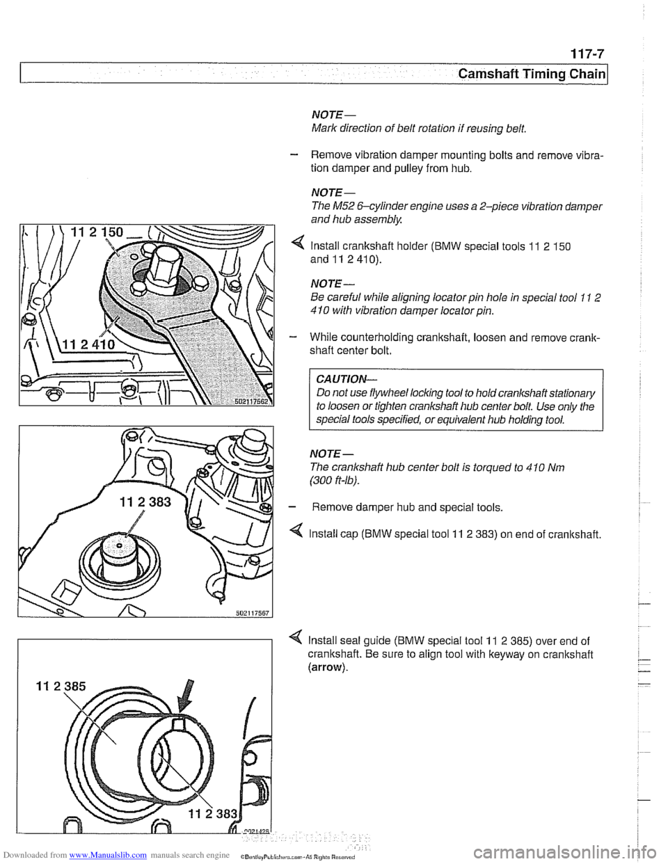
4 Install crankshaft holder (BMW special tools 11 2 150
and11 2410).
NOTE
-
Be careful while aligning locator pin hole in special tool 11 2
410 with vibration damper locatorpin.
- While counterholding crankshaft, loosen and remove crank-
shaft center bolt.
CAUTION-
Do not use flywheel locking tool to hold crankshaft stationary
to loosen or tighten crankshaft hub center bolt Use only the
special tools specified, or equivalent hub holding tool.
NOTE- The cranlshaft hub center bolt is torqued to 4
10 Nm
(300
ft-16).
- Remove damper hub and special tools.
4 Install cap (BMW special tool 11 2 383) on end of cranltshaft.
4 Install seal guide (BMW special tool 11 2 385) over end of
crankshaft. Be sure to align tool with keyway on crankshaft
(arrow).
Page 244 of 1002
Downloaded from www.Manualslib.com manuals search engine
1 17-8
Camshaft Timing Chain
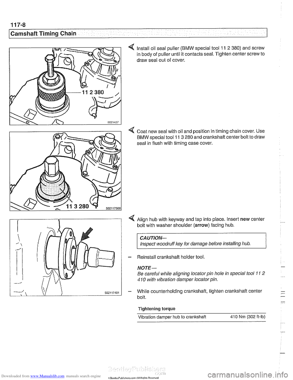
4 Install oil seal puller (BMW special tool 11 2 380) and screw
in body of puller until it contacts seal. Tighten center screw to
draw seal out of cover.
4 Coat new seal with oil and position in timing chain cover. Use
BMW special tool
11 3 280 and crankshaft center bolt to draw
seal in flush with timing case cover.
4 Align hub with keyway and tap into place. Insert new center
bolt with washer shoulder
(arrow) facing hub.
CAUTION-
Inspect woodruffl
NOTE-
Be careful while aligning locator pin hole in special tool 1 I 2
410 with vibration damper locator pin.
- While counterholding cranltshaft, tighten crankshaft center
bolt.
Tightening torque Vibration damoer hub
to crankshaft 410 Nm (302 ft-lb)
Page 245 of 1002
Downloaded from www.Manualslib.com manuals search engine
Camshaft Timing Chain
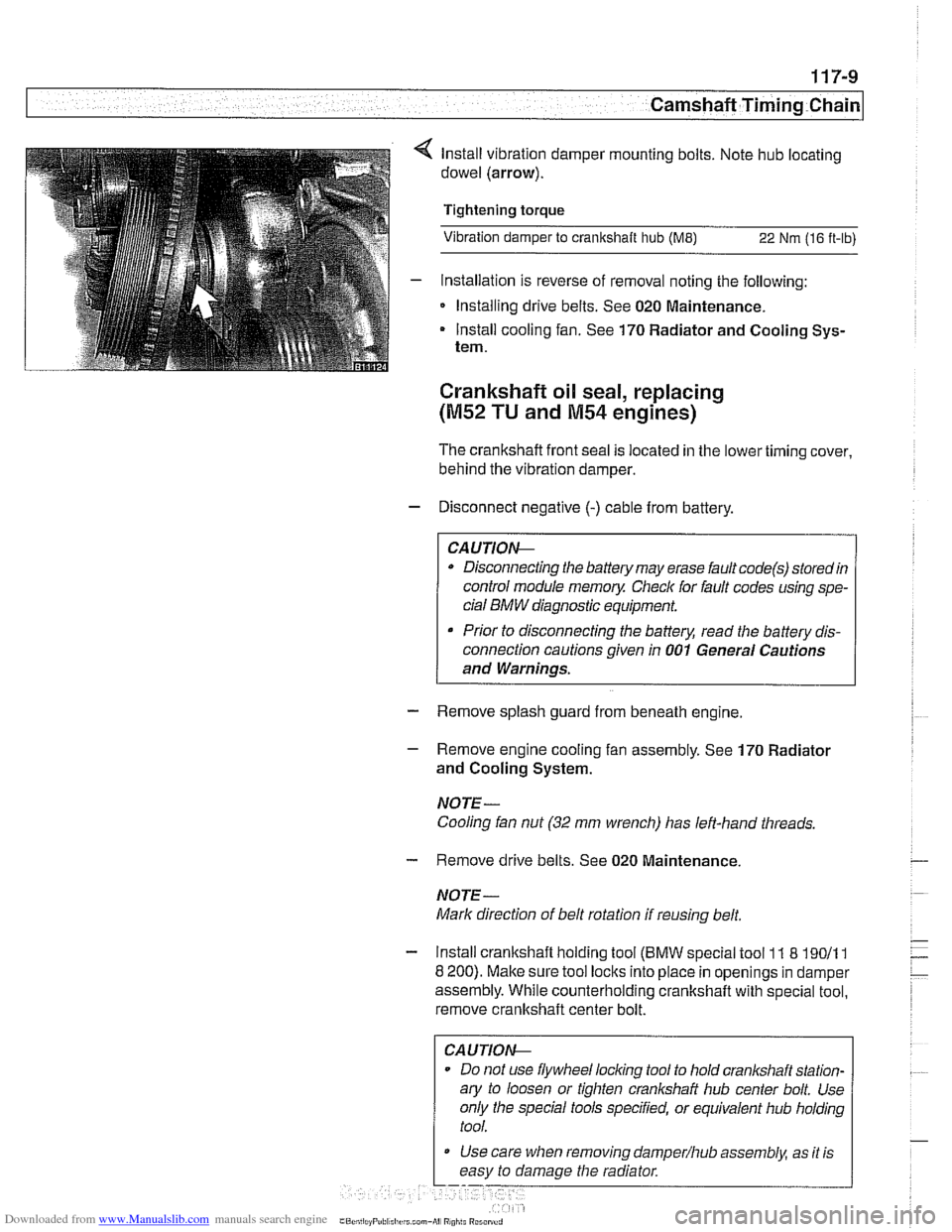
lnstall vibration damper mounting bolts. Note hub locating
dowel (arrow).
Tightening torque
Vibration damper to crankshaft hub
(ME) 22 Nm (16 ft-lb)
- Installation is reverse of removal noting the following:
Installing drive belts. See 020 Maintenance.
Install cooling fan. See 170 Radiator and Cooling Sys-
tem.
Crankshaft oil seal, replacing
(M52 TU and M54 engines)
The crankshafl front seal IS located in the lower timing cover,
behind the
vibrat~on damper.
- Disconnect negative (-) cable from battery.
Disconnecting the battery may erase fault
code(s) storedin
control module memoy Checlc for fault codes using spe-
cial
BMW diagnostic equipment.
Prior to disconnecting the battery, read the battery dis-
connection cautions given in
001 General Cautions
and Warnings.
- Remove splash guard from beneath engine
- Remove engine cooling fan assembly. See 170 Radiator
and Cooling System.
NOTE- Cooling fan nut
(32 mm wrench) has left-hand threads.
- Remove drive belts. See 020 Maintenance
NOTE-
Mark direction of belt rotation if reusing belt.
- Install crankshaft holding tool (BMW special tool 11 8 19011 1
8 200). Make sure tool locks into place in openings in damper
assembly. While counterholding crankshafl with special tool,
remove crankshaft center bolt.
CAUTIOI\C
Do not use flywheel locling tool to hold crankshaft station-
ary to loosen or tighten
cranl(shaft hub center bolt. Use
only the special tools specified, or equivalent hub holding
tool.
Use care when removing
damper/hub assembly, as ~t is
easy to damage the radiator
Page 246 of 1002
Downloaded from www.Manualslib.com manuals search engine
117-10
/Camshaft Timing Chain
NOTE-
The crankshaft hub center bolt is torqued to 410 Nm
(300 ft-lb).
- Install crankshaft damper puller (BMW special tool 11 8 21 0)
to
11 8 200. Use bolt to remove damper from crankshaft.
- Oil seal replacement:
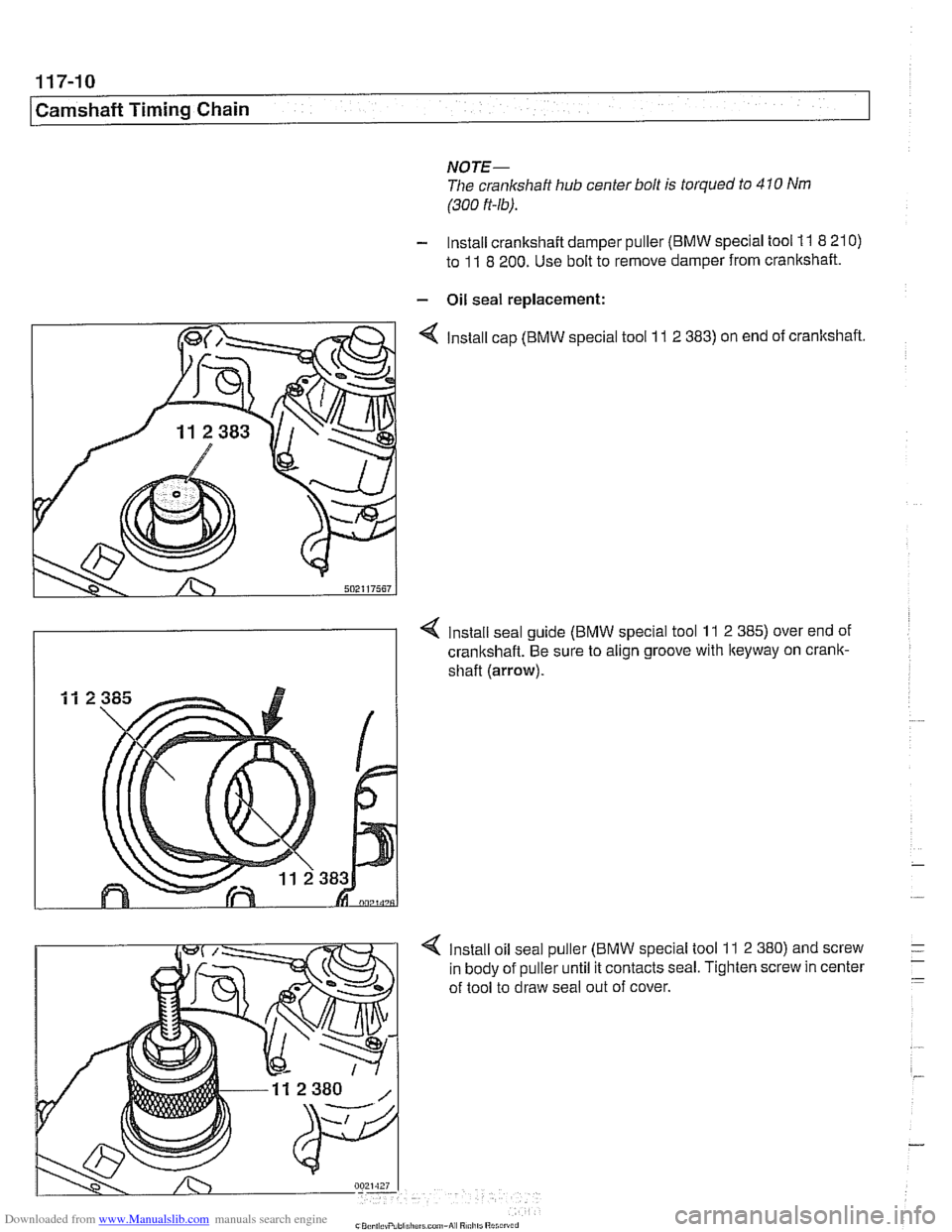
4 Install cap (BMW special tool 11 2 383) on end of crankshaft.
Install seal guide (BMW special tool
11 2 385) over end of
crankshaft. Be sure to align groove with
lteyway on crank-
shaft (arrow).
4 Install oil seal puller (BMW special tool 11 2 380) and screw
in body of puller until it contacts seal. Tighten screw in center
of tool to draw seal out of cover.